| John Broskie's Guide to Tube Circuit Analysis & Design |
13 October 2006
Small Improvements
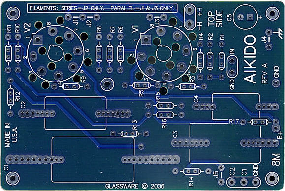
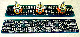
New mono octal PCBs
I have remarked before that three topics make up the majority of my e-mail from readers: tube phono preamps, tube headphone amplifiers, and shunt regulators. What I find intriguing is that, unlike me, none of my audio buddies are fans of headphones (or as the Brits say, “cans”). In fact, it's just the opposite: they disdain them vehemently. And much the same attitude towards headphones holds true for those who long ago happily divorced from vinyl, with no interest in resuming the relationship. (On the other hand, shunt regulators are of interest only to highly-technically-minded tube fanciers who are, perhaps, a mere 10% of the already tiny tube club.) So here is my fear: if I were to title the following section of my blog “Headphone amplifier design,” many will tune out, having no interest in headphones. Yet, the underlying logic is not restricted to headphone amplifiers. What to do?
Here’s an analogy. When I lived in Scotts Valley, California, I lived on the side of a mountain, where a neighbor, digging in his garden, found a small nugget of gold—the real yellow metal, not a metaphor. So did I start digging up my backyard? No. I wasn’t even tempted, as I was too busy to hunt for what may not have existed. On the other hand, say while raking the leaves, I were to stub my big toe on a chunking-big gold nugget, great. This mirrors many a tube fancier’s view on informative articles that won’t be read. No doubt many of these seemingly off-topic articles are chock full of gold nuggets; alas, few are moved to dig for them. For example, an article on, say, modifying an old Fisher tuner may contain some long-sought, much-needed answer to some long-labored-over, much-cursed problem; but we also know that it may not. It is that uncertainty that keeps us from prospecting. This is always a problem, for me as much as for anyone else, as gold nuggets can be found—and often can only found—where you least expect them.*
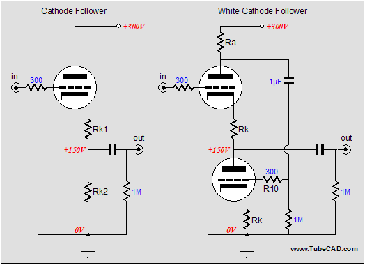
Therefore, in deference to you, my hurried reader, let me push forward from my mountain of words a few nuggets for your big toe's perusal. The first is that making a White cathode follower circuit optimal requires using a plate resistor equal to the inverse of the triode's transconductance, which is good as true with high-rp triodes and low-impedance loads, but with low-mu triode, such as the 6AS7 or 6BX7 and high impedance loads, finer resolution is needed. In other words, a more accurate equation is needed. The second nugget is the circuit modification to cathode followers and White cathode followers, which is not limited to the “cans” fans, as a any circuit that holds a tube follower will benefit from this technique: for example, a first-rate line-stage amplifier can be made using it.
Optimal White cathode followers revisited About a year later Alex Cavalli e-mailed me, pointing out that the Ra = 1/gm was close, but not exactly correct, as far as SPICE simulations and empirical testing revealed. So, I reevaluated my mathematical reasoning and I found that he was right, that I had missed a term. I wrote back to him explaining that I found the error and I had fixed the optimal-Ra formula. His reply was that he too had come up with the true optimal-Ra formula and that he planed on revealing it in an article he planned on writing. I left the topic with him and I never posted the new formula. We never shared formulas, so I don’t know if we agree and I don’t know where his article appeared or if it did appear at all. Thus, this might be old news, but the formula for finding the optimal plate resistor value is: Ra = (rp + 2RL)/mu, where RL equals the load impedance. From a quick inspection, we see that the lower the load impedance, the closer the formula comes to: Ra = rp/mu On the other hand, when the load impedance is as much as 300 ohms and the rp as low as 280 ohms, as it is with the Sennheiser HD-650 headphones and a 6AS7, then the adjustment is fairly large. The 6AS7’s mu of 2 and rp of 280 ohms yields 140 ohms in the simple inverse of gm calculation, but they yield 370 ohms in the new optimal-Ra formula. So how important is this fine-tuning? If you are using a 6AS7, very important; if you are using a 12AX7, very little, as the 12AX7's 80,000-ohm rp swamps out the 300-ohm load. Nonetheless, as much as I am a fan of increased exactitude, I am also opposed to the practice of false exactitude. For example, some poor tube fancier, armed with the new optimal-Ra formula and a tube manual, looks 6DJ8 and he finds that the 6DJ8 holds an rp of 2,640 and a mu of 33.
Hoping to drive 300-ohm headphones, he then calculates that Ra should equal 98.181818181818181818181818181818, which he then tries to find. Aside from the ridiculous precision, this resistor value is fundamentally ludicrous, as the specified tube characteristics are only correct at one cathode-to-plate voltage and cathode current, otherwise they are way off. What? How can that be? The tube manual’s list of characteristics is about as accurate as your weight and height was in high school is today. Plate resistance and transconductance vary. Amplification factor comes the closest to being a true constant, but only because the other two vary in a related fashion. (In fact, mu is the least concrete characteristic of the three.) So what good is the optimal-Ra formula—or any other tube circuit formula? Well, if nothing else, the formulas get you close to where you should be. Even 98.1818… is much better than the old assumption that the higher the plate resistor value, the better, so a constant-current source would have to prove best. And if someone just happened to build a 6DJ8-based White cathode follower with a 90-volt cathode-to-plate differential and 15mA idle current, as the tube manual specified, the 98.1818… value would be right on the mark. On the other hand, if the 6DJ8 sees a 125-volt cathode-to-plate differential and a 10mA idle current, where the mu is 29.7 and the rp is 3,030 ohms, and where the load is 300 ohms, the better value would be 122 ohms, with 120 ohms being close enough for all but the most anal-retentive of solder slingers. (If 32-ohm headphones are the intended load, with the same current-voltage values, then Ra should equal 104 ohms, which isn't that far off from 122 ohms.)
Improved followers (line stage and headphone amplifier emphasis) Actually, in keeping with the first law of engineering (“Nothing of value comes without a cost”), this extra resistor’s added benefits must be paid for with a higher output impedance and slightly less voltage and current swing. Whereas a standard 6SN7-based cathode follower would offer an output impedance of 400 ohms, the extra-resistor modified cathode follower can easily present twice that impedance. When driving interconnects, this increase is negligible; but it becomes significant when driving low-impedance headphones. Yet this is what I am about to recommend, i.e. using un-bypassed cathode resistors in all cathode followers, including the White cathode follower output stage. Why? The un-bypassed cathode resistors improve the performance of a line-stage amplifier and headphone amplifier to such a high a degree that the accompanying higher output impedance must be both paid for and accepted. True, Grado headphone listeners are not going to like this modification, but those who listen to Sennheiser HD-580, HD-600, HD-650 and the higher-impedance AKG headphones are going to be well pleased. I am. I own a pair of Sennheiser HD-650s and they are supremely revealing of associated equipment, whereas the Grado SR-225s that I also own are much more forgiving, which is a virtue with 99% of audio equipment. (No, I haven’t heard the new Grado GS100 reference headphones but I would love to give them a test drive.) And those who just want a supremely fine line-stage amplifier will find this new option a welcome increase in flexibility.
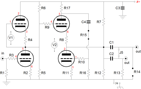
In the above schematic, we see the complete Aikido line-stage/headphone amplifier, with its White cathode follower with extra un-bypassed cathode resistors. The schematic refers to the new octal mono PCBs, but it applies equally to the 9-pin versions, save for the pin numbers (text in red). The critical resistor is Ra, the plate resistor of the White-cathode-follower output stage. The revised formula, given above, was based on the assumption that the bottommost cathode resistor would be bypassed or that fixed bias would be used for the bottom triode and that resistor R8 between triodes wouldn't be used. So how does the formula perform, given these changes to the topology? It must be modified, but the modification is simple enough: Ra = (rp + 2RL)/mu + Rk Thus, for example, using a 6DJ8 working under a 125-volt cathode-to-plate differential, a 10mA idle current, 280-ohm cathode resistors, and into a 300-ohm load, the optimal plate resistor value is 402 ohms (122 ohms plus 280 ohms, in other words). So is this modification really worth doing? I think so, for two major reasons. The first is that I hate placing anything in series with a cathode, other than an un-bypassed resistor. Many forget that the cathode has a slightly greater gain than the grid, which is a big oversight, as any weirdness or failing at the cathode will be amplified in phase at the plate (remember the ground-grid amplifier). A resistor placed in series with the cathode, on the other hand, linearizes the triode’s transfer function. The second reason is that the distortion spectrum changes to the ear’s benefit. Often with the added resistors the second harmonic does not drop—in fact, it might rise a tad—but the higher harmonics, say the 4th, 5th, 6th, 7th, fall a great deal. This a great deal, swapping away some second harmonic for getting rid of higher harmonics. The downside is the increased output impedance, which may prove a deal breaker for some. My recommendation is to experiment a bit and try the added cathode resistors; I am sure that you will like what you hear. //JRB
*In point of fact (as the Brits like to say), after I had had exhausted the obvious sources for tube gold, such as the Radiotron Designers Handbook, Vacuum Tube Amplifiers, and old issues of Audio Engineering, I had to dig into less obvious sources. I am glad I did, as veins thick with nuggets were there for the taking. For example, look into articles and books that deal with tube-based DC amplifiers and instrumentation for some easy gold mining.
|
|
|||


| www.tubecad.com Copyright © 1999-2006 GlassWare All Rights Reserved |