| John Broskie's Guide to Tube Circuit Analysis & Design |
31 October 2006 Boo!
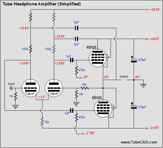
It's Scary Time Did you know there is something called "e-mail bankruptcy"? Up until a few months ago, I didn’t. What happens is that someone falls so far behind in answering e-mail that he knows that he will never catch up, so he files for e-mail bankruptcy by deleting all his unanswered e-mail—after, of course, sending a blanket e-mail to everyone in his mailbox that states that he has no hope of ever replying to the hundreds of piled up e-mails and that he will diligently try to keep up to date with all the new incoming e-mails he receives. An interesting predicament. I remember reading in an interview with Alan Cooper, the author of The Inmates Are Running the Asylum: Why High Tech Products Drive Us Crazy and How to Restore the Sanity, that he thought that the missing killer program was one that could allow better e-mail management. “E-mail! How could e-mail be such a big deal?” I thought as I read his comments. I also remember talking to a famous tube-audio personality (believe me, you know his name) and my being startled by how enraged he became at the mention of e-mail. His face turned red and his eyebrow hairs seem to stick out perpendicular to his forehead. “E-mail, more damn e-mail…” he began to say, as if it were a bitter poison he was spitting out. Once again, "How strange," I thought. At the time, however, I only received a few e-mails a day, none of which was spam. Today, I understand the e-mail problem all too well, as every day I receive at least two dozen solid e-mails and one hundred spam e-mails. Actually, the one hundred spam messages are what cannot be filtered away by two ISP anti-spam filters, Norton Anti Spam, and my own rule-based spam filter. In other words, the original 5,000 to 10,000 spam e-mails that would end up in my mailbox are reduced to one hundred, just 1%, or less, of the real total. Unfortunately, I know that good e-mail is not getting to me, that the spam filtering is too aggressive and prejudiced. Prejudiced? The assumption is that e-mail that originates from other countries is more likely to be spam. More than half of my e-mail, however, comes from outside the United States. (I am working on a workaround to this problem, but I am not there yet.) About four days ago, I saw an incoming e-mail at the ISP’s web-based e-mail program, the first stop of my e-mail’s trip to my mailbox. This e-mail, alas, did not make it all the way past the filters. If I had caught its absence on that first day, I could have fished for it in folders of deleted mail, but I didn’t notice that it was missing until the day after, when all the deleted e-mail is really flushed away. Sorry. Its subject mentioned tube headphone amplifiers and the writer asked if any of my designs could be used with a 12AX7, 6DJ8, or, ideally, a 6BQ5. He also specified 2V of output as a goal, no output coupling capacitors, and simplicity. Let’s start with the assumptions. I assume that the mystery writer’s headphones are the high-impedance kind, such as the 300-ohm and 600-ohm type from AKG and Sennheiser, as 2-volts of peak output is deafening with low-impedance headphones, such as the Grados. For example, I just bought a pair of AKG K26Ps 32-ohm headphones for use with my laptop and the the stated efficiency is 126dB per volt! Second, I assume that not that much gain is required, as CD players and iPods put a fair amount voltage already. Third, I assume that he wishes to point-to-point wire the headphone amplifier, as his request for simplicity seems to imply. My last assumption is that he wanted something along the OTL line, not a transformer-coupled design. Non-Aikido headphone amplifier
Wait a minute, that’s not an Aikido amplifier. True. The Aikido was disqualified because of the coupling capacitor it requires at its output. This circuit, on the other hand, resembles an old-time tube-based OpAmp, save for the lack of DC coupling between the input stage and the output stage. How does it work? The 12AX7-based differential amplifier accepts the input signal and provides the feedback input for the output signal. It provides an open-loop gain of about 26. If the amplifier offered infinite gain, then the closed-feedback-loop gain would equal (30k + 10k)/10k, or 4. But as the amplifier’s gain is less than 26 (the output stage tubes are configured as cathode followers), the actual gain into a 300-ohm load will be closer to 3 times the input signal, which should be plenty. Cathode followers in the output stage? Both output tubes realize 100% signal degeneration. In the case of the top triode, this is obvious, as the triode is obviously configured as a cathode follower. The bottom triode is effectively also configured as a cathode follower, as it provides less-than-unity gain and its output matches the top triode’s. (I have covered this type of amplifier configuration many times before; here is a good link to more information: Totem-pole Output Stage PSRR ) Now the amplifier could be rearranged so that the output stage would provide voltage gain. In the schematic below we see how to convert the output tubes to grounded-cathode amplifier topology.
The unhappy face signifies that the design holds a critical flaw (which would be, nonetheless, included in many a high-end product)—namely, the negative power supply rail’s noise will be presented to the top triode’s grid, but not to the bottom triode's grid. There is a trick that ensures that the noise will be in phase at both grids, where then the output stage should reject most of the noise; but why tax the output stage at all, when we can fix the problem altogether? If we replace the 75k common cathode resistor of the input differential pair with a constant-current source, then the negative power supply rail noise will not be superimposed on the balanced drive signal.
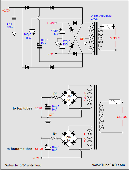
Note that the bipolar power supply now holds +/-170 volts, which is easily created from two 120-volt secondary windings, as are found in isolation transformers intended for international use. The 510V power supply rail is derived from the +/-170 volts power supply.
The voltage differential between top and bottom output tubes is too great (165V) to allow using a single heater power supply for all the tubes, so two heater power supplies are used instead. So is this the perfect tube headphone amplifier? Who knows. Let someone build it and we can give a thorough listening. Is this the headphone amplifier that I would want to build? Well, yes; but just because I like the look of it. My fondness for 6BQ5s is showing, as I am not convinced of its potential sonic superiority. I would be, however, afraid to hook up my Sennheiser HD-650s to it without out first adding some active protection circuitry, such as a DC servo and a window comparator and a clamping relay at the output. Nor am I convinced that doing away with the coupling capacitor at the output really buys us any sonic improvement. So, what would I build instead?
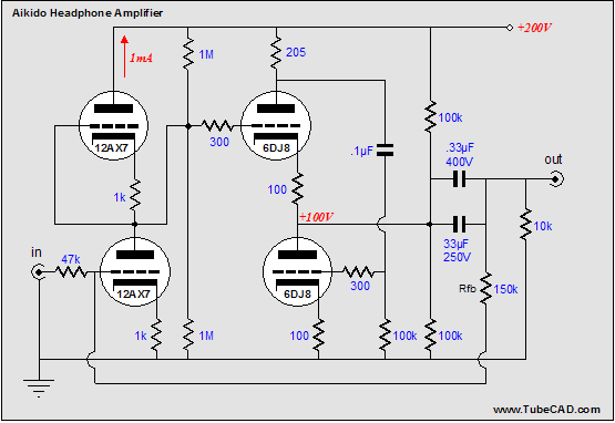
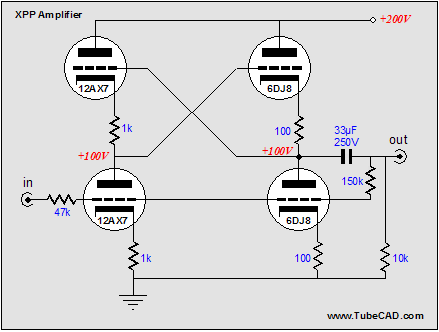
This Aikido headphone amplifier uses a feedback loop to lower the gain and distortion and output impedance. It could easily be built on one of my PCBs or point-to-point wired. The power supply is much simpler and cheaper to build. Of course, if simplicity is the highest goal, it is hard to beat the XPP amplifier, as shown below.
Two tubes per channel and only one capacitor and seven resistors—now that is one simple circuit. The 6DJ8 output triodes could be replaced by 6BQ5s, which would allow upping the B+ voltage to 300 volts. Grid-stopper resistors could be added a few other touches could embellish this simple amplifier without undoing its fundamental simplicity. Still, for the more ambitious, the 6BQ5 design is intriguing, although much more complex. //JRB
|
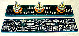
The TCJ Stepped Attenuator The center knob controls both channels, and offers six large decrements; the flanking knobs offer six fine decrements for each channel, creating a volume control and balance control in one easy-to-use stepped attenuator. This clever attenuator uses fewer resistors (only 32) than would be expected from a conventional 32-position stepped attenuator, as two series attenuators would need a total of 72 resistors; and two ladder attenuators would require 140 resistors. In addition, the PCB holds dual sets of resistor pads, one wide and one narrow, so that axial (composition, wire-wound, and film) and radial (thick-film and bulk-foil) resistors can be used without extra lead bending. Although designed to go with the Aikido amplifier, it can be used anywhere a high-quality attenuator is needed, whether passive or active. For example, it would make a first-rate foundation to an excellent passive line box. Designed by John Broskie & Made in USA Visit our Yahoo Store for more details: http://glass-ware.stores.yahoo.net/
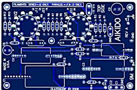
 Aikido PCBs for as little as $24
Only $12.95
www.glass-ware.com
|
|||

).png)
).png)
.png)
 d
d


| www.tubecad.com Copyright © 1999-2006 GlassWare All Rights Reserved |