| John Broskie's Guide to Tube Circuit Analysis & Design |
05 February 2007 More Feedforward Shunt Regulators I have been thinking about the feedforward shunt regulator (FSR) and I thought it would prove interesting to convert the solid-state circuit from EE Times's Website www.planetanalog.com—shown below—into a tube circuit. In other words, create a tube-based OpAmp to drive a power triode’s cathode to follow its input signal.
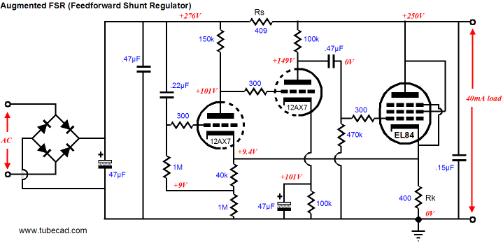
The above circuit’s operation was covered in blog 95, but the idea is a simple one: if the power supply noise to the left of resistor Rs is superimposed on top of resistor R1, then the modulated current flowing through resistor R1 must also flow through resistor Rs, which results in the power supply noise being nulled at the resistor Rs’s right side of the circuit. To translate this circuit into vacuum-state, we just replace the MOSFET with a triode-connected pentode, the EL84 for example, and we replace the OpAmp with a two grounded-cathode amplifiers in cascade. The feedback is 100%, as all the variation on the EL84’s cathode is entirely relayed to the leftmost 12AX7’s cathode, where such a variation results in a large countering signal at the EL84’s grid. Thus, 100% the power supply’s noise, sampled from the 0.22µF capacitor, will be superimposed on the top of the EL84’s cathode resistor. Or will it? Because of the limited gain that the tubes provide, only 97.8% of the noise signal gets imposed. Thus, there is a discrepancy between resistors, Rs and Rk, which would normally equal each other. The inverse of 0.978 against 400 ohms equals 409 ohms.
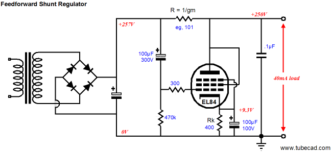
Note how this arrangement differs from the simpler topology shown below, wherein the EL84's own effective internal resistance divided by its amplification factor effectively creates a 101-ohm resistor. Also note how the rightmost 12AX7’s plate resistor terminates on the other side of Rs. Why? It was a nod to the realization that the load driven will create its own power supply perturbations that must be countered as well as the raw power supply’s noise contributions. In other words, I wanted the noise on the right of resistor Rs to be fed back to the EL84’s grid, so that the EL84 would buck such noise. Unfortunately, the 100k plate resistor is in series with the 12AX7’s own 80k plate resistance, which means that only 55% of the noise makes it to the EL84’s grid. Furthermore, the EL84’s wimpy transconductance against the 409-ohm series resistor provides very little gain. In other words, not much signal-induced noise bucking can take hold here and an extra regulator stage is needed.
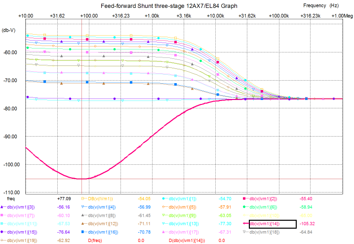
Considering the increase in complexity, what advantage does the augmented feedforward shunt regulator hold over the simpler, singe-tube version? The theory is that the feedback will allow a wider range of parts values and a deeper null with off-the-shelf parts that are not hand-selected to work best. Aside from lower distortion and output impedance, one of the big advantages feedback-based designs hold is that the parts can age and drift off value without the output moving off target. Based on my limited SPICE analysis of this circuit, this advantage seems to apply (an improvement of about -20dB). Nonetheless, the deepest nulls occurred with precise resistor Rs value trimming, as the graph below makes clear.
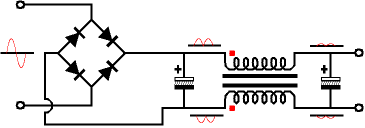
In fact, it seems to me that the best way to proceed would be to use two potentiometers in parallel with resistor Rs, one for coarse adjustments and the second for fine adjustments. (The secret to using two potentiometers is to set the fine-adjustment potentiometer at the center of its range, then adjust the coarse-adjustment potentiometer until the deepest null is achieved, then adjust the fine potentiometer to find an even deeper null.) By the way, we can create a passive equivalent of the active feedforward shunt regulator by using a common-mode choke.
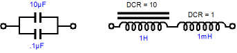
Common-mode chokes consist of two equal windings about a common core. They are often wound on toroidal cores and usually only offer little inductance and little DCR resistance, as their intended use is high-current applications. C-core and IE-cores can also be used and a higher inductance could be realized, if we are willing to live with a much higher DCR. (I would love to play with a common-mode choke made from the same materials and techniques as used in the manufacture of high-quality audio output transformers.) By the way, everyone knows how to improve a coupling capacitor’s performance by adding a small-valued bypass capacitor across the larger-valued capacitor. But how do you bypass an inductor? You cannot add a small-valued, air-core choke in parallel with a clunky, power-supply-grade choke, as inductances, like resistances, decrease when placed in parallel. The answer is to place small, high-quality choke in series with the clunker.
(I once performed an audio test of chokes and I was shocked at how poor the performance was of the average choke. Yes, they worked quite well between 100-250Hz, but beyond this narrow frequency band they were horrendously bad, as anyone who has built a para-feed amplifier using a junk-bin choke can readily attest.)
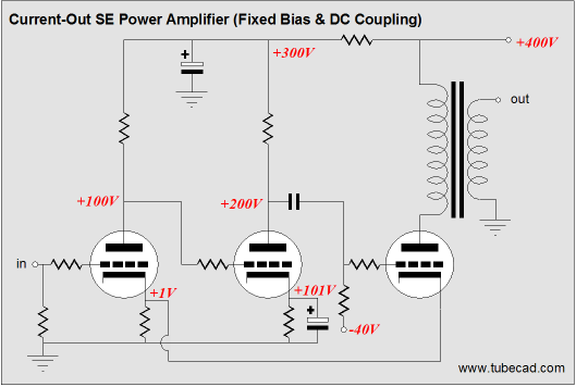
First-watt amplifier Why build such an amplifier? Certain loudspeakers prefer a strictly defined current rather than voltage. The brilliant Malcolm Hawksford wrote an interesting paper titled, “Distortion Reduction In Moving-Coil Loudspeaker Systems Using Current-Drive,” wherein he explains the advantages of a current amplifier over a voltage amplifier. Now think about the big liability of using vacuum tubes as power devices: high internal resistance, which results in a high output impedance. A high output impedance is a very bad thing in a voltage amplifier, but a positive feature in a current amplifier. Furthermore, one big problem with triode-based single ended amplifiers is that the primary’s reflected impedance is in series with the triode’s plate resistance. This defines a two-resistor voltage divider and the power supply noise gets divided, with (usually) two thirds falling upon the primary and being reflected to the secondary. So, oddly enough, a high-plate-resistance pentode relays less power supply to the loudspeaker, as most of the noise voltage falls across the pentode, not the primary. See the article from TCJ April 99 for more details. In a tube-based current amplifier, even if a low-impedance triode such as the 300B or 6C33 is used, the output tube’s plate no longer offers its plate resistance to the primary; instead, the output impedance at the plate is nearly infinite, so the percentage of power supply noise that is superimposed across the primary will be virtually nil, which means the secondary will also be free of noise.
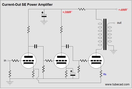
In the schematic above, we see a feedback-based amplifier that strives to define a signal voltage across resistor Rk; and by doing so, regulates the current through that resistor, ignoring the output tube’s plate voltage. In other words, this amplifier works like a variable constant-current source. (Complementarily, the voltage amplifier works like a variable voltage source.) Okay, this is all interesting enough, but what does it have to do with feedforward shunt regulators? The answer lies in the topological similarities between the schematic above and the schematic of the augmented current amplifier shown at the top of the page. The two feedback loops relay current draw information back to the input tubes. If it does not look like the amplifier uses 100% feedback, then your eye is a good one, as the cathode resistor reduces the feedback ratio, so that some current gain can be realized.
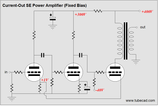
If we add a negative power supply rail and use a mixture of fixed and cathode bias, then 100% feedback is achieved and we end up with a topology similar to the augmented current amplifier shown at the top of the page.
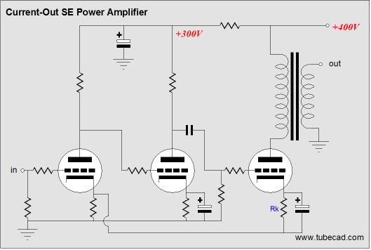
Or, if no negative power-supply voltage is available, we can bypass the output tube's cathode resistor.
Remember that the output transformer prevents any steady DC voltage or current output; similarly, the bypass capacitor only relays AC current draw information to the input stage. As a safety measure, the output transformer's secondary can be bridged with two 33V zeners in series (anodes facing each other), which will protect the amplifier in the absence of a load. //JRB
|
|


| www.tubecad.com Copyright © 1999-2007 GlassWare All Rights Reserved |