| John Broskie's Guide to Tube Circuit Analysis & Design |
|
24 June 2007
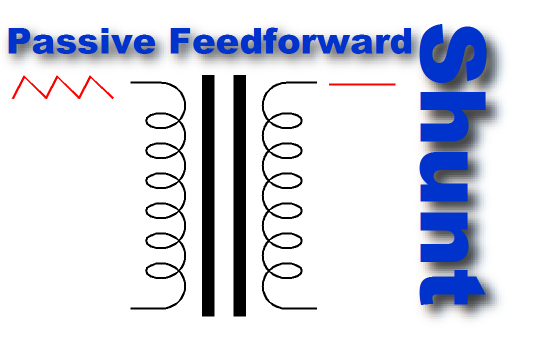
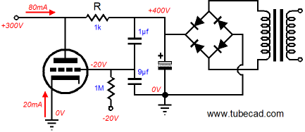
Active versus passive: that's the choice we often face in audio design, and each approach holds its advantages and disadvantages. Passive filters, for example, are usually big, heavy, and expensive; whereas active filters are often smaller, lighter, and cheaper. (Well, this holds true at least at lower frequencies; at higher frequencies, the tables may turn, with the passive filter being smaller, lighter, and cheaper.) In addition, the passive filter is less likely to reach voltage clipping or current saturation, whereas the active filter is likely to be easily overdriven. In other words, there is no clear winner overall, only winners for each set of objectives. Now, the question is, "Which is better for power supply noise elimination a passive feedforward shunting circuit or an active feedforward shunt regulator?" Wait a minute, there’s no such thing as a passive feedforward shunting circuit. Oh, did I forget to mention that I created one? (Once again, we witness the triumph of understanding over memorization; I know that are thousands and thousands of tube lovers in the world who have memorized scores of tubes, but who cannot explain how a triode works.) Below we see a one-to-one isolation transformer and a resistor and capacitor that effectively mimic the feedforward shunt regulator.
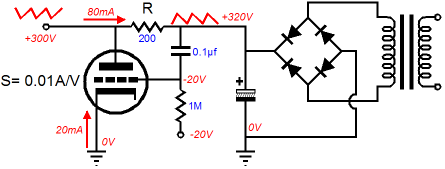
The idea is that the power supply noise will induce current spikes through the transformer’s primary and that when the current spike is reflected to the secondary, the current spike will flow through series resistor R, thereby countering the power supply noise. Wait a minute—the astute reader will say—the transformer’s primary should undergo no current spike, as the primary and the capacitor are reactive components. Well, this is true in the ideal sense, but real transformers are made from real wire, which holds real resistance, so the primary is effectively working into its DCR, so any power supply noise will induce a current noise equal to the noise voltage dived by the DCR. Okay, I know this is getting a bit too theoretical, so before anyone moves on to Google or Yahoo to see what Paris Hilton is up to, let's look at the following schematic to see how the circuit is actually laid out.
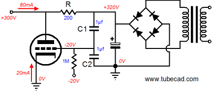
As each winding is effectively in series with its DCR (DC resistance), the power-supply-noise induced currents will flow through both the secondary’s DCR and the series resistor R. Since the secondary’s DCR robs half of the secondary’s potential current transfer, the series resistor must equal twice the DCR. How well does the passive feedforward shunt circuit work? In SPICE, the results are spectacular, reducing the power-supply noise by over -60dB. No doubt, once again, reality will disappoint, proving only remarkably good. The first problem is that the higher the primary and secondary inductance, the better the circuit works. Unfortunately, real isolation transformers only hold so much inductance. Second, the greater the shunting capacitor’s capacitance, the better the circuit works; high-voltage and high-capacitance, however, do not go together that well, or should I say that they do not go together cheaply. Third, isolation transformers seldom hold perfectly matched windings. In fact, the winding ratio often is often skewed in favor of the secondary, so that losses in the transformer can be overcome. In other words, some tweaking of the series resistor’s value will be required. Last, unless the transformer holds an air-gap, either explicitly with an obviously break in the magnetic circuit or implicitly in the sloppy construction of the transformer’s core, the transformer will magnetize in the face of the DC current flowing from primary to secondary. Yes, the voltage drop across the series resistor cannot be too large, being only 5V to 10V, the current would only equal Vdrop/(2DCR). Nonetheless, the induced current could easily saturate a tight magnetic core, such as held by the toroidal transformer. So the better approach, when using a non-airgapped transformer, would be to use two separate shunting capacitors to ground, as shown below.
Now if only I were bit more on the ball, I would build such a passive feedforward shunt circuit, stuffing it in a pretty plastic box, adorned with a snappy name—such as the “Ultra Ripple Stripper” or “Mega-Fluxer”—and a $400 price tag. I take back that remark about me not being on the ball. I should have written, "If only I were less on the ball." As I have written here before, the optimal number of original ideas for anyone to have is one. For example, if the last circuit was my lifetime’s only original achievement, I could zealously promote it and it alone. I could vociferously argue against all other approaches to power supply filtering, and I could make a bundle. Instead, I have already thought of an alternative circuit that uses no series resistor and requires only one large-valued shunting capacitor. Give me an other hour and I'll come up with another circuit... Maybe I should take up listening to rap, although you would imagine that two screaming young children would be enough to kill all thought, whether it be creative or not. Before looking at the bottom of the page to see what this circuit looks like, see if you can come up with the topology on your own.
Feedforward Shunt Regulator Explication (Part 27)
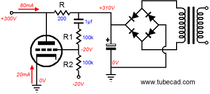
But what if we were to use a resistor twice as large (say 200 ohms, rather than 100 ohms), with a triode that offered a transconductance of 10mA/Volt? Well, in the stock circuit, as shown above, the ripple voltage would remain the same as a power supply with no feedforward shunt regulator, except that the ripple’s phase would be inverted. For example, a 1Vpk positive-going pulse on the raw power supply rail, would induce a positive 10mA increase in current conduction in the triode, which would yield a 2-volt negative-going pulse on the other side of the series resistor, but as the other end of the resistor was going up by 1 volt, the output side of the resistor goes down by only 1 volt. Now, if we were to halve the triode’s input signal, then the triode would respond with only a 10mA negative-going pulse at the output, thereby canceling the positive-going pulse. So how do we lose half of the input signal? A two-resistor voltage divider immediately comes to mind.
Of course, two capacitors in series also create a voltage divider.
In fact, we can divide the input signal down to an even smaller percentage, by using a larger bottom capacitor. For example, in the schematic below, we see the raw power supply noise being divided by 10 before presenting it to the triode’s grid.
How else can we divide the input signal to a useable value? How about a resistor/triode voltage divider? Here the triode's rp replaces a resistor.
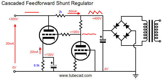
Before moving on the new circuit, let’s review the failings of the feedforward shunt regulator. Failings? I thought the circuit was perfect! Well, it is certainly good at eliminating power supply ripple from the B+ voltage, but it is largely ineffective at neutralizing amplifier-induced noises on the power supply rail. Remember disturbances come from many sources: some are airborne, such as electromagnetic pollution from neon signs, nearby radio stations, electric motors, and AC filament wires; other noises travel from floor vibrations, transforming our delicate tubes into microphones; and other noises are the result of each stage within the load circuit tugging and releasing its grip on the B+ voltage. The feedforward shunt regulator only looks forward, creating a counter noise signal to null the original power-supply-induced noise. Unfortunately, it is blind to what develops on the other side of the series resistor. In contrast, the feedback-based shunt regulator sees only the disturbance on the output side of the series resistor. Now, what would happen if we wed the two approaches together? The late Dr. Gizmo used to remind me over and over again, "Think baby steps, or you will lose half of your readers." So, in deference to his memory, we will take our first step. The single triode in a shunt regulator can be replaced by two triodes in cascode.
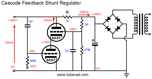
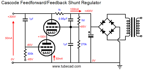
In the above schematic, we see the mighty 6AS7 arranged in cascode. The bottom triode is fed all of the input signal and the top triode merely locks the bottom triode’s plate voltage and relays any variation in current conduction to the series resistor. Now, let’s make the top triode do a bit more work, by feeding it a new input signal, the power supply on the input side of the series resistor.
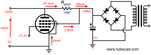
Note the 1k series resistor, which is about seven times larger than the inverse of the 6AS7’s transconductance. But the top triode cannot summon as much effective transconductance, as its cathode sees the 280 ohms of rp from the bottom triode. Here we see a rare example of having our cake and eating it too, as the feedback-based shunt regulator requires the largest series resistor possible and the feedforward shunt regulator requires a series resistor appropriate to the input signal and device transconductance. In many ways, a pentode is similar to a two triodes in cascode, so why not replace the 6AS7 with a pentode? The first step is to specify a series resistor equal to the inverse of the pentode’s screen transconductance.
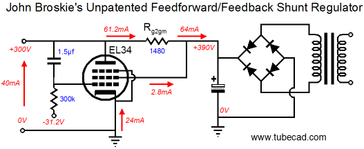
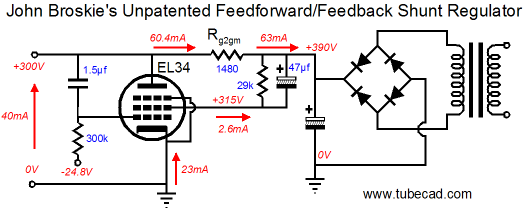
The second step is to feed the output into the pentode’s grid. The schematic below displays one possible example of John Broskie’s Unpatented Feedforward/ Feedback Shunt Regulator. Of course, different pentodes could be used, as could cathode bias. (There might be a real advantage in the fixed bias approach, as a variable bias voltage might allow precise power supply noise nulling on the output.)
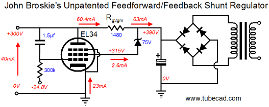
The only danger, maybe “limitation” is a better description, is the maximum voltage limit for the screen. In some pentodes, it is substantially lower than the plate voltage limit. The workaround in these cases is to use a voltage dropping zener or bypassed resistor.
With voltage dropping resistor:
Yes, I know that many do not approve of pentodes, but even the most prejudiced will have to admit that this circuit is quite elegant (and cheap).
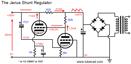
Finally, we arrive at the circuit that I wanted to start with, but that I feared would not make sense without some mind stretching first. The circuit below makes use of both the feedforward shunt regulation and conventional feedback-based shunt regulation. The 12AX7 both voltage divides the raw power supply ripple and amplifies the output perturbations. The 12AU7 both shunts away the power supply ripple and the load-induced noise on the output. the only thing missing is the protection diode that should span from the 12AX7’s plate to the 12AU7’s cathode, which would limit the maximum positive grid-to-cathode voltage on the 12AU7 to less than 1V.
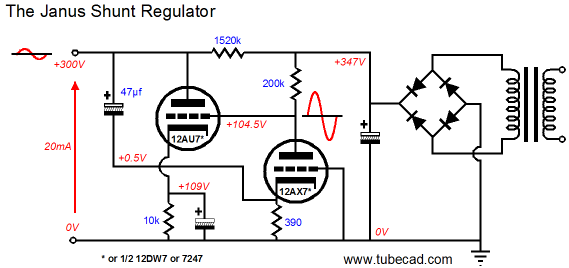
Looking at the power-supply noise created by audio signals circulating through the B+ connection, we see how the Janus regulator erases much of the offending noise.
I know that a few readers are laughing to themselves: "A 12AX7 and 12AU7, what a fool. Who would actually use those lame tubes? " Well, the secret is that it is the topology, not the tube types that make a new circuit. 300Bs or KT88s or 845s or 6C33s can be used in this topology. The fact that these lowly triodes can deliver sterling results is a testament to the topology's soundness.
//JRB
Variation on the Passive Feedforward Shunt Circuit
Speaking of originality, the great H. L. Mencken wrote in his introduction to his brilliant and funny book, In Defense of Women, that
|
Only $12.95
Download or CD ROM www.glass-ware.com
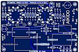
High-quality, double-sided, extra thick, 2-oz traces, plated-through holes, dual sets of resistor pads and pads for two coupling capacitors. Stereo and mono, octal and 9-pin printed circuit boards available.  Aikido PCBs for as little as $24 http://glass-ware.stores.yahoo.net/
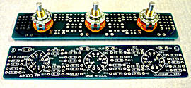
The TCJ Stepped Attenuator The center knob controls both channels, and offers six large decrements; the flanking knobs offer six fine decrements for each channel, creating a volume control and balance control in one easy-to-use stepped attenuator. This clever attenuator uses fewer resistors (only 32) than would be expected from a conventional 32-position stepped attenuator, as two series attenuators would need a total of 72 resistors; and two ladder attenuators would require 140 resistors. In addition, the PCB holds dual sets of resistor pads, one wide and one narrow, so that axial (composition, wire-wound, and film) and radial (thick-film and bulk-foil) resistors can be used without extra lead bending. Although designed to go with the Aikido amplifier, it can be used anywhere a high-quality attenuator is needed, whether passive or active. For example, it would make a first-rate foundation to an excellent passive line box. Visit our Yahoo Store for more details: http://glass-ware.stores.yahoo.net/
The Tube CAD Journal's first companion program, TCJ Filter Design lets you design a filter or crossover (passive, solid-state or tube) without having to check out thick textbooks from the library and without having to breakout the scientific calculator. This program's goal is to provide a quick and easy display not only of the frequency response, but also of the resistor and capacitor values for a passive and active filters and crossovers. TCJ Filter Design is easy to use, but not lightweight, holding over 60 different filter topologies and up to four filter alignments: While the program’s main concern is active filters, solid-state and tube, it also does passive filters. In fact, it can be used to calculate passive crossovers for use with speakers by entering 8 ohms as the terminating resistance. Click on the image below to see the full screen capture.
Tube crossovers are a major part of this program; both buffered and un-buffered tube based filters along with mono-polar and bipolar power supply topologies are covered. Available on a CD-ROM and a downloadable version (4 Megabytes). Download or CD ROM
|
|||


| www.tubecad.com Copyright © 1999-2007 GlassWare All Rights Reserved |