| John Broskie's Guide to Tube Circuit Analysis & Design |
|
19 August 2007
6H30Pi EH Octals Some of these 9-pin tubes are dirt cheap and sound great in an Aikido line amplifier, such as the 6BQ7 at less than $2. Other 9-pin triodes can cost $300 each and also sound great, such as the cinch-waist 6922s from the Amperex. But beyond price range, 9-pins tubes offer many more choices in terms of gain and output impedance. Therefore, considering the spare pickings with octal tubes, the 6H30Pi is truly a welcome addition, particularly as it fills in a notch in the present lineup. How's that ? When driving low-impedance headphones or long lines of high-capacitance cables, the 6SN7 type triode just doesn't cut it. Okay, but don't the 6BL7 and 6BX7 already fill that bill? No, not really. Here's why: the following table shows the results for all five triodes at 100V cathode-to-plate voltage and 0V grid-to-cathode voltage.
Notice that for the 6H30Pi's heater current increase of only 225mA we get a nearly tenfold decrease in output impedance over the 6SN7 in a cathode-follower configuration. Also note that the only other triode that beats the 6H30Pi is the 6AS7, but at the cost of nearly three times the heater current and much too high an idle current and far less linearity. Now imagine an Aikido headphone amplifier with a 6SN7 input tube and a 6H30Pi output tube and a pair of Sennheiser HD650s and a big smile on your face and a green tint to your friend's faces. By the way, check out this link www.head-fi.org/forums/ and look carefully at the pictures of gear; search for the phrase "the bomb." In other words, expect to see Aikido octal headphone amplifier kits soon at the GlassWare Yahoo Store. (The kits will include 33µF, 630Vdc, polypropylene coupling capacitors.)
Update on the
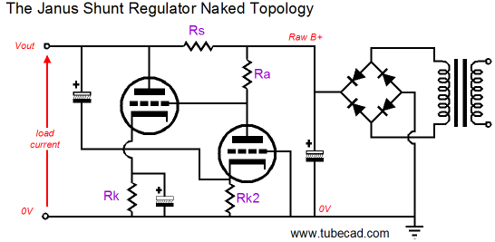
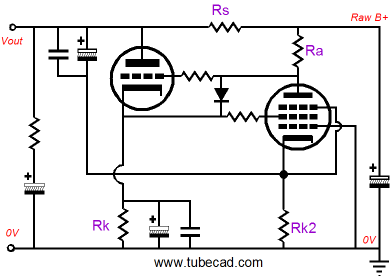
As something of a preamble, I have borrowed from John Derbyshire the phrase "congress critters," which I much prefer to "senators and house representatives" or, God save us, "congresspersons." Well, I understand that congress critters have a simple formula: for every angry or praise-filled phone call , e-mail, or letter that they receive, there are one hundred voters who felt the same way, but didn't bother to make the effort. So if the same ratio holds for TCJ readers, then there are about 400 to 500 who are confused about how the Janus shunt regulator works. Thus, a review and tuneup are required. Below, we see the Janus topology laid bare.
The Janus shunt regulator uses both feedforward shunt regulation and feedback-based shunt regulation to eliminate both the raw power-supply noise and the signal-induced noise from its output. The rightmost triode does double duty by voltage dividing the raw power supply ripple and by amplifying the error signal at the output, before passing the signal to the leftmost triode's grid. The leftmost triode then inverts this input signal at its plate, thereby neutralizing the error signal at the output. In my original description of the topology, I had used a 12AX7 and 12AU7. The topology is not limited to these tubes in any way. In fact, I pointed out that:
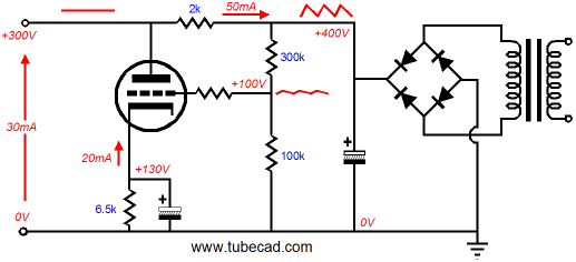
The message that came across, however, was that while different tubes could be used, the same plate and cathode resistor values would stay fixed. No, simply no. No such thing was implied (well, at least not intentionally by me). Different tubes, different resistor values. In fact, the same tubes with different B+ voltage, different resistor values. For example, look at the data table above in the 6H30Pi section and notice how none of the values for rp and mu matches the one listed in the tube manual for these triodes. How is that possible? A triode's rp, mu, and gm are not chiseled in titanium plates sealed in a vacuum; instead they are a fluid blend from one extreme to another extreme. In other words, it makes little sense to specify a triodes rp and gm without also specifying the cathode-to-plate voltage and cathode current at which these characteristics were obtained. Getting the rp and transconductance right is critical to obtaining the best performance from the Janus shunt regulator. For example, the rightmost triode voltage divides the power supply noise in the fashion as a two-resistor voltage divider would, except that the triode’s rp takes the place of a bottom resistor.
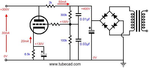
In the equivalent schematic above, we see the power supply noise reduced to a fourth of its B+ value; thus, the series resistor’s value must equal four times the inverse of the leftmost triode’s transconductance; in this example, 0.002A/V, as 2k * [100k/(100k + 300k)] = 500 ohms, the inverse of which equals 0.002. Had the triode's gm been 10mA/V, then a 400 ohm series resistor would be needed, as 1/0.01 = 100, which against (100k + 300k)/100 equals 400 ohms. By the way, one problem the above circuit would face in reality is the pass tube’s high-input capacitance, due to Miller-effect enhancement. The 300k voltage divider resistor in parallel with it 100k brother equals an output impedance of 75k, which working into the magnified grdi-to-plate capacitance of the pass triode can too greatly limit the shunt regulator's high-frequency bandwidth. A simple workaround would be to bypass the voltage divider resistors with small capacitors, as shown below.
These added capacitors reduce the voltage divider output impedance at high frequencies. (Note how the larger-valued capacitor goes on the bottom, not the top, as is the case with the resistors.)
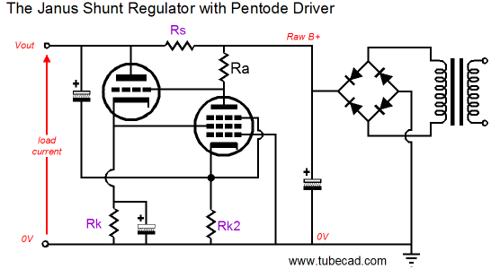
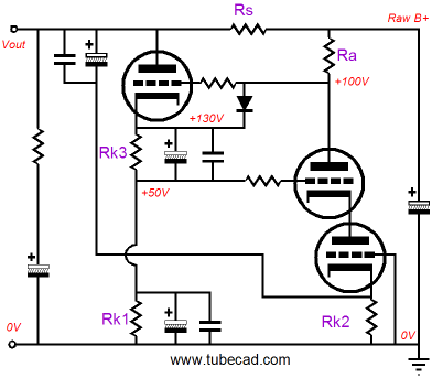
Pentode Driver Tube in the Janus Regulator
Now that you have had a minute to digest this circuit, let’s move on to the important missing details. At startup, when the cathodes are cold, but the B+ voltage is fully realized, do we really want the pass tube’s grid to be at +400V, while its cathode is at 0V? Adding the solid-state diode takes care of that problem, as it only conducts when the grid is more positive than the cathode, which it never is once the tubes are hot and conducting. Next, the all-important grid-stopper resistors are in place to prevent wild oscillations at 40MHz. Finally, high-quality bypass capacitors make up for clunky electrolytic capacitor’s failings.
Wait minute, where are the tube types and part values? I think I’ll leave them out this time (think of working the values out on your own as homework). One place that I would start looking for pentodes is in triode-pentode tubes, such as the 6AN8, 6BM8, 6AU8A, 6AW8… All of the tubes so far mentioned are 9-pin types, as octal triode-pentode tubes are rare; and the few that do exist have connections on the top of the glass envelope (eight connections are not enough, once the heater’s two are subtracted). Or, if discrete triodes and pentodes are going to be used, I would look into 6AU6, 6BY7, and the 6SJ7GT for the pentode. The key pentode feature is sharp-cutoff and it would not hurt to have an audio-use history. The triodes can start at the 6C4 and 6J5, move up through the 12B4 and 2A3, and end at the 300B and 845 (of course, triode-connected pentodes, such as the EL34 and EL84 can—and perhaps should—be used). One last thought: as I have said in the past, when you see a pentode, think cascode instead.
Cathode resistors Rk1 and Rk3 voltage divide the pass triode’s cathode voltage, making the DC connection to the cathode voltage possible. (In the cascode circuit, the top triode's grid should never be at a voltage more positive than than its plate.) Both the cascode and pentode variation share a common attribute: the pentode and cascode offer an extremely poor PSRR, which means that almost all the power supply noise will be relayed to the pass tube, which in turn means that the series resistor’s value will be much closer to just the inverse of the pass tube’s transconductance; in other words, smaller in value, which may mean too much output voltage, depending on the current drawn by the load. Another bad result stemming from a smaller-valued series resistor is that too little voltage gain may be be developed by the pass triode. On the other hand, the driver gain will be so much higher that the lower-valued series resistor may not hinder the shunt regulator’s overall performance with signal-induced perturbations on the output voltage. As you can deduce, it quickly gets complicated, but then that's what makes for interesting homework.
Next Time //JRB
|
Only $12.95
Download or CD ROM www.glass-ware.com
goldpoint™
SInce 1995, Goldpoint™ has provided equipment designers and audio enthusiasts the best 24-position level controls made. We offer completely assembled and "blank" stepped attenuators.
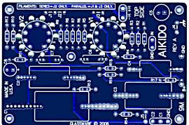
High-quality, double-sided, extra thick, 2-oz traces, plated-through holes, dual sets of resistor pads and pads for two coupling capacitors. Stereo and mono, octal and 9-pin printed circuit boards available.  Aikido PCBs for as little as $24 http://glass-ware.stores.yahoo.net/
|
|||||||||||||||||||||||||||||||||||||||||||||


| www.tubecad.com Copyright © 1999-2007 GlassWare All Rights Reserved |