| John Broskie's Guide to Tube Circuit Analysis & Design |
|
05 November 2007
MJ Audio Technology OTL Design
My efforts in fixing the design had two aims: to preserve drive balance between top and bottom triodes and to greatly improve the PSRR of the amplifier. The interesting feature that these two aims share is that so few care about them. How is that possible? One possible reason is that the problems of drive imbalance and poor PSRR are usually hidden in an OTL amplifier. OTL amplifiers usually use a great gob of negative feedback; they have to, otherwise their output impedance, distortion, and noise will be far too high. Much like great gobs of makeup, which can hide large blemishes, negative feedback can hide large topological blunders—at least at idle or on the test bench. For example with no input signal, a high-feedback push-pull amplifier—both OTL and transfomer-coupled—can measure near noiseless. But once an input signal moves the output stage out of its small class-A operating range, the once-vanquished noise returns full force, mixing with the output signal, making a heavily congested and grungy sound. This hidden noise (or dynamic-induced noise) eludes the simple measuring techniques used by most: holding one ear to a loudspeaker with the amplifier on and with a grounded input; and attaching a scope or AC-voltage meter to the output, with a grounded input. It will show up, however, on a distortion analyzer, as the reading is the sum of harmonic distortion and noise. But even this measuring technique faces a problem. Let me take the long way to an explanation. One TCJer wrote to me saying that I had overplayed the role of power-supply noise in an OTL amplifier, that although the normal bridge rectifier feeding two large power supply reservoir capacitors did make a lot of nasty noise, using a choke-based pi-filter on both the positive and negative power supply rail would fix everything.
No doubt about it, inductors would help lower the power-supply noise at idle. But what happens after a large burst of input signal? Assuming that high-inductance chokes are used, even the beefiest chokes present a fairly high DCR resistance because of the long length of wire needed to achieve high inductance. Ideally, the DCR should be less than a tenth of an ohm. Unfortunately, a 5A, 1H choke with 0.1-ohm DCR that didn’t weigh as much an entire Krell power amplifier would be a miracle; a 10-ohm DCR would be fatal. Here’s why: a 36W OTL must be able to deliver peak current swings of +/-3A into 8-ohm loads and 3A through 10 ohms equals a voltage drop of 30 volts. In other words, our +/-210V rails will fall to +/-180V (probably much lower, as the power transformer’s primary also holds a high-DCR resistance). Well, if the OTL amplifier can still meet its 32W specification, who cares if the rail voltage collapses? The company that made the OTL amplifier and the technician who tests the amplifier do not care, but the music lover listening to the amplifier will care, as the amplifier will stumble while playing music. When the power supply rails collapse, the driver stage must also track the changes in voltage. If it doesn't, it will not be able to keep the bottom triode from seeing far too large a negative bias voltage.
Imagine the bottom triode seeing its cathode suddenly become +30V more positive, while its grid still sees the fixed negative bias voltage of -240V. A triode that can conduct 50mA with 210V across its cathode and plate and with a -30V at its grid will not be able to conduct much, if at all, with -60V at its grid. Likewise, the top triode needs to see 30V/mu less negative bias just to keep conducting at 50mA with the lower +180V positive rail voltage. In other words, after the crescendo, this OTL will be in trouble until the voltages return to their nominal vales at idle. On the other hand, if we anticipate that the rail voltage will collapse during sustained bursts of output, we can design the driver stage to adapt on the fly to the rail voltage sags. Ideally, the driver and output stage should steadfastly weather expanding and contracting power supply rails, much as a dock and boat rise and fall in unison with rising and falling of the tide. In other words, designing a good OTL takes a bit more care than a conventional push-pull transformer-coupled amplifier. And testing an OTL also takes a bit more care, and different test procedures. For example, tone bursts, unlike constant sinewaves, are quite useful in spotting output stage stumbling.
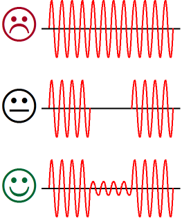
The problem with the continuous sinewave is that the inter RC time constants will adjust to the full output and the collapsed rail voltages, so little distortion will be revealed on a scope. (Note well that the usual procedure for testing an amplifer's distortion is to wait a bit, while the amplifier “settles down,” before evaluating the distortion; missing exactly what is most important to music reproduction, the amplifier’s ability to amplify a hugely varying input signal without stumbling. Doesn't single-ended amplification seem like a better, if not saner, choice now?) The problem with the tone bursts of sinewaves alternating with zero signal rests is that nothing gets tested; the amplifier may recover before the next set of sinewaves is presented to its input. The two-level tone bursts, on the other hand, deliver the results we seek, as we can see how well the first few sinewaves look after the full-output sinewaves. 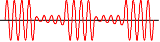
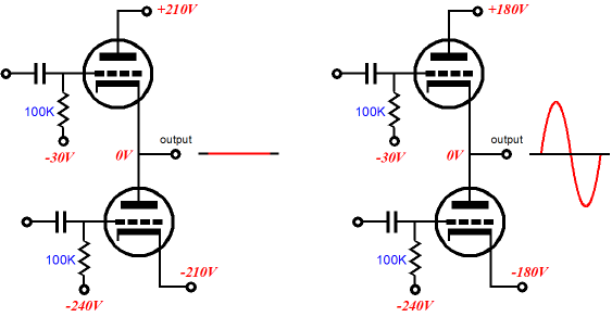
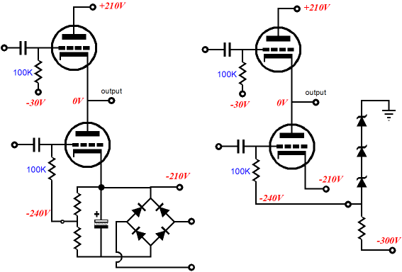
The Partial-Regulation Problem For example, compare the two circuits below. Which is better?
If you guessed the circuit on the right, then you are wrong (and you need to learn how to read paragraph headings more carefully). The problem lies with the fixed -240V working with other unfixed voltages in the amplifier. For example, the negative rail voltage falling to only -180V, during full output; or the wall voltage running high where you live, so the negative rail runs at a dangerous -225V at idle. Dangerous because only -15V of bias voltage exists between the bottom triode’s cathode and grid and because the greater cathode-to-plate voltage. Here is the analogy: rather than let a boat float with the tide level, you decide to nail portions of the boat to a large post that helps holds up the dock. Surely a little fixed positioning is better than none, you might be tempted to think. Don’t. Instead, think very carefully what the result will be when other voltages drift away from their intended targets. This admonition (cautionary advice) applies to transformer-coupled amplifiers as well.
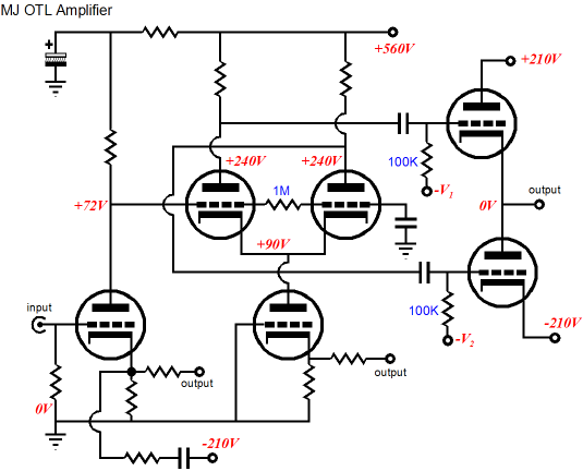
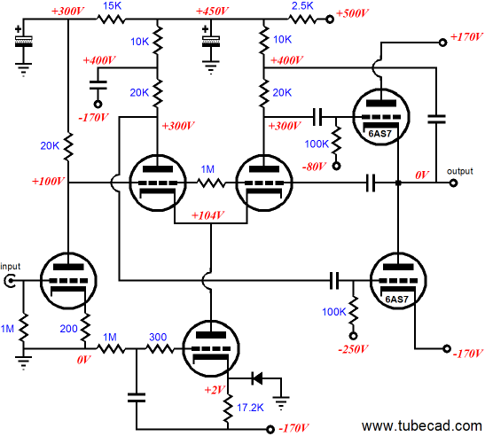
A 6AS7-Based OTL The answer is that while the 6AS7 could be forced to work in that topology, lower rail voltages would better suit the 6AS7. Ideally, something like +/-140V would be great; realistically, +/-170V is easier to implement, as those are the rail voltages that derive from using a 240Vac center-tapped power transformer. What follows is a cluster of schematics on a two themes—each with the 6AS7/6080 as the intended output tube, with each 6AS7 triode drawing 50mA of idle current. How many output tubes should be used in parallel? It depends on how much heat you tolerate and many watts of output power you desire. A realistic range might be four to ten 6AS7s per channel.
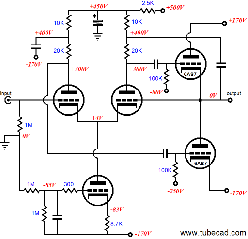
The amplifier above works on the assumption that the long-tail phase splitter’s cathode load comes close to approximating a constant-current source. It also holds a marketing treasure: it makes use of a negative feedback loop that not one in ten audio reviewers could have a hope of finding. Of course, you, like all your fellow TCJers, found it immediately; but then you are not the target audience for the glossy ads. Remember, if you are not caught, you are not guilty. (Can you tell that I am already bracing myself for the new OJ trial and book deal?) A little more seriously, the capacitor that bridges the output to the long-tail phase splitter applies a 100% feedback ratio across the phase splitter and output stage. The input tube sits outside this feedback loop, so whatever distortion it brings to the output signal will be faithfully passed on to the output, which should make all of us a tad nervous. Compromised signal in, compromised signal out. What if, on the other hand, we used a better input stage? For example, an Aikido amplifier. Below, we see the phase splitter and output stage extricated from the amplifier above.
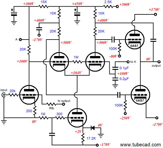
Now, we can use whatever input circuit we desire, as the circuit is a power unity-gain buffer. Still, the two coupling capacitors are a bit troubling, as the signal source is likely to use its own coupling capacitor at its output and the buffer’s output is already at ground potential, so couldn’t a DC-coupled power buffer be created?
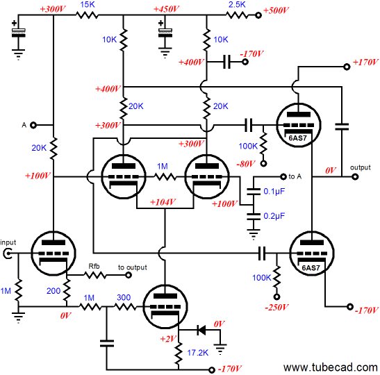
With a wave of the wireless computer mouse, it is done. In the above circuit, the coupling capacitors have been removed and the constant-current source’s triode has been shifted down.
This power buffer is missing critical fuses and grid-stopper resistors (and maybe a few protection diodes), but it is close to being actually build-worthy. A nice touch would be to add cathode followers to drive the 6AS7 grids directly. Furthermore, a few hundred more negative volts for the constant-current source to use would not hurt. (Remember, if you use a 240Vac center-tapped power transformer, getting 510Vdc and -340Vdc [and -510Vdc] is easy.) On the other hand, if using any more triodes than absolutely necessary offends your sensibilities and wallet, then the following circuit might be the better choice.
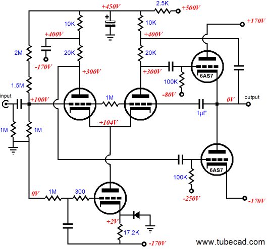
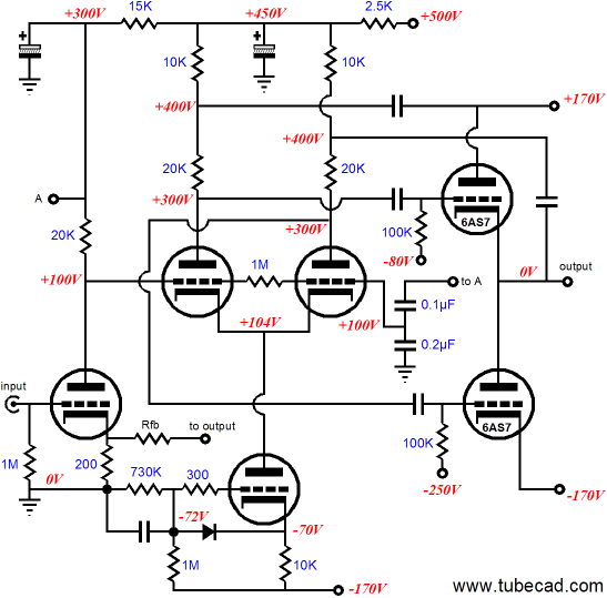
The above amplifier uses a global negative feedback loop to encompasses the input stage, phase splitter, and output stage. The power supply noise that leaks from the input stage’s output is met by a two-capacitor voltage divider at the other side of the phase splitter. (By the way, this is an old technique that Marantz used in their famous power push-pull amplifiers.) The following amplifier circuit does not use an ideal constant-current source; instead, it uses a special quasi constant-current source that will inject the negative power supply rail noise into the phase splitter. Why? To keep the noise out of the output signal. Additionally, it might be easier to tune in terms of internal time constants, so that the amplifier just glides over wildly varying current swings into the loudspeaker.
Ideally, the voltage relationships within the any OTL amplifier will remain in proportion to each other, no matter what the input signal, just as a movie’s image would remain proportional, no matter what size the screen and distance from the projector. //JRB
|
High-quality, double-sided, extra thick, 2-oz traces, plated-through holes, dual sets of resistor pads and pads for two coupling capacitors. Stereo and mono, octal and 9-pin printed circuit boards available.  Aikido PCBs for as little as $24 http://glass-ware.stores.yahoo.net/
Support the Tube CAD Journal & get an extremely powerful push-pull tube-amplifier simulator for TCJ Push-Pull Calculator
TCJ PPC Version 2 Improvements Rebuilt simulation engine *User definable
Download or CD ROM For more information, please visit our Web site : To purchase, please visit our Yahoo Store:
|
|||


| www.tubecad.com Copyright © 1999-2007 GlassWare All Rights Reserved |