| John Broskie's Guide to Tube Circuit Analysis & Design |
08 December 2007
Essential Gadget
You might remember my mentioning last year, in a list of Microsoft Zune improvements, that what is needed is a half-foot-long headphone jack extension that would allow the headphone’s plug to safely pull out of the extension. Well, the good folks at Replug, LLC have a better solution: a short, flexible, two-inch extension that breaks away at its base, when too strong a tug pulls at it. The (easily-removable) plug remains in its unharmed jack and the extension can be quickly snapped into place. Brilliant. The animated GIF image above shows the aptly-named Replug in action. It works superbly well. I was too lazy to do any serious testing when I initially plugged in my Replug, but soon enough it saved the day. It’s getting cold in California—a laughable assertion for the most of the country, I know—but cold enough for me to wear a thicker jacket. Well I wasn’t used to wearing the jacket and listening to headphones at the same time and I caught the headphone cable on a branch while walking the dog. The Replug did just what it was designed to do: it saved my Zune and my headphones. Just as it happened, I realized how well-designed the Replug is, as my AKG headphones terminate into a right-angle plug, which would never simply unplug from the half-foot-long headphone jack extension I had suggested, as the right-angled plug and free-floating jack form a 45-degree angle when pulled tight, holding fast.
Additionally, the Replug helps preserve your headphone jack. Jacks are fragile devices that can withstand only so many insertions before their grip slackens, creating the curse of headphone use: the painfully annoying intermittent connection. Much better to replace an inexpensive ($18) Replug every few years, rather than trying to replace the iPod or laptop’s headphone jack. Bravo Replug for making life just a tad less stressful. How does the Replug sound? A fair question for an audiophile to ask, although maybe a silly question for everyone else. I could hear no difference, with and without the Replug; and my magnet failed to grab anything within the Replug. If you are worried about the extra mechanical connection, then use some contact conditioner twice a year.
Okay, what didn’t I like? To be frank, I only wish that I had thought of it first. More seriously, I would love to see an expansion in Replug versions. For example, most of my headphones are terminated with quarter-inch plugs and they will not work with the Replug’s 3.5mm jack. Adding a headphone converter to the Replug would be neither elegant
nor ergonomic, so what is needed an array of Replugs: 3.5mm to 3.5mm, 3.5mm to 0.25", 0.25" to 0.25", and 0.25" to 3.5mm. Why the last one? Many pieces of high-end gear sport a 0.25" headphone jack, which requires a 3.5mm converter to work with the high-end ear buds from companies like Shure and Etymotic. And, no doubt, many audiophiles will be turned off by the Replug’s low price, so to appease these auricly-auscultated spendthrifts a deluxe, $300, gold soaked, beryllium cored, Teflon-jacketed, cryo-treated, fairy-dusted version could be offered for those for whom only the most expensive will do.
Philips DVD Micro Theater MCD908
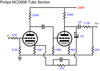
I actually had the chance to listen to the MCD908 a few days ago. The local Fry's Electronics store sells it, although they apparently didn’t know how to hook it up. So after my friend Glenn and I set things straight, what did I think of the sound? I cannot honestly comment, as all we could listen to was FM radio without an antenna and I could not pick up my favorite radio station. Of course, what interests me most about this little gem is the taking it apart and then modifying it. The tube stage is a somewhat competent, but nonetheless rather silly affair, with the 12AX7 working in a low-gain, high-feedback line stage amplifier.
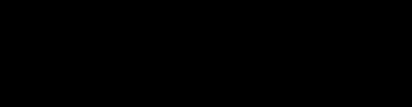
Before we dig into the actual circuit, let’s look at what brackets the circuit: two fixed voltage dividers. The first comprises the input 47k resistor and the 8.2k grid resistor, which reduces the input signal down to 15% or -16.5dB. The second voltage divider is found at the output and it holds 3.3k and 22k resistors, which reduces the output signal down to 87% or -1.2dB. Why all the attenuation? To do away with the gain from the tube line stage amplifier of course. The power amplifier does not require a preamp, so the tube circuit’s role isn’t to provide gain, but tube warmth and glow. Why else would you run the 12AX7s so leanly? Why would you drag down the input tube with a 150k load and the output tube with a 25k load other than because you wanted distortion. Yet, the circuit uses a fair amount of feedback. Well, how do we gracefully back out of the stock circuit? At the very least, I would lose the 12AX7 in a flash and plug a 12AU7 in its place. Then I would change a few parts values, while keeping the existing topology.
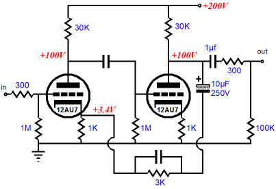
The gain is only a bit lower than the 12AX7-based version, but the feedback ratio has dropped hugely, which can only improve the sound. Since the voltage dividers have been scaled back, the power amplifier’s gain would need to be reduced. And because we are running so much more current through the line stage amplifier, the power supply will need some adjusting to achieve the same 200V B+ voltage. Fortunately, the power supply uses a simple RC filter to smooth the B+ voltage. Ideally, we would lose the stock tube circuit altogether and start fresh. Imagine using an Aikido line amplifier with four tubes glowing through the front window. Or, perhaps, just a single 12B4-based grounded-cathode amplifier per channel, which might just be possible with a good amount of PCB hacking, if there is enough room, as the 12B4 stands 2.375 inches tall in its socket, whereas the 12AX7 stands 1.9375 inches tall. On the other hand, we could fairly easily use a 12AU7 with both its triodes in parallel.
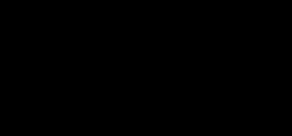
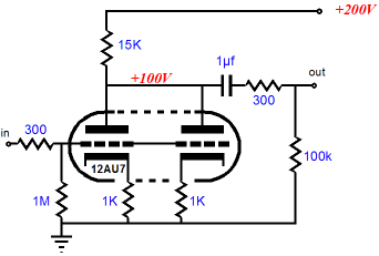
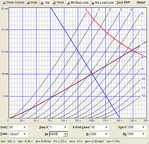
In general, I am fearful of using just two triodes in parallel, as I have always found that I prefer the sound from a single triode. In this case, however, where the original circuit was so off the mark, I am confident that the parallel triode would still be a huge improvement. In fact, I would be willing to test the limits of the high-voltage power supply by using a lot more current and more plate voltage, as shown below.
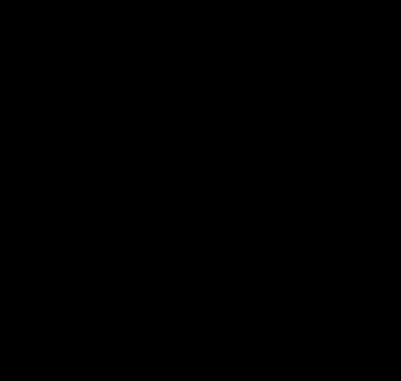
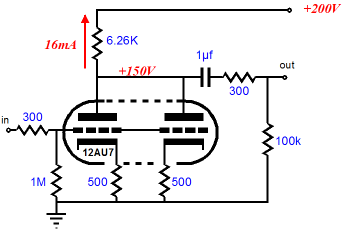
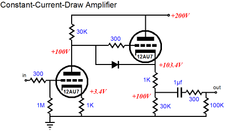
Much better. Increasing both the plate voltage and the idle current moves the 12AU7 into its more linear region and will allow the line stage amplifier to drive capacitance more readily, not that there are any line outs on the MCD908 (of course, they could be added, with the help of a drill and some skill). The downside to the heavy current draw is that the power supply will be even more taxed by both the high idle current and the signal-induced current variations, which might subtract from our freshly won sonic gains. An alternative circuit is the constant-current-draw amplifier shown below.
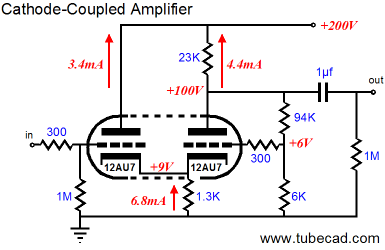
The cathode follower works in an anti-current-phase relationship to the grounded-cathode amplifier, so if the two stages are equally loaded, the net current draw from both stage remains constant. (The key issue is not that the two idle currents match, but that the two signal currents cancel. So the grounded-cathode amplifier should draw more idle current, as the cathode follower will work into both its cathode resistor and the external load impedance.) The diode, for those new readers, is not part of the circuit during normal use, as it is reverse biased, as the cathode follower’s cathode is more positive than the grounded-cathode amplifier’s plate. But at startup, when the triodes are cold and not conducting, the diode forward biases and conducts, protecting the cathode follower’s triode from cathode stripping. (Do you really want the grid to see +200V and the cathode to see 0V at the same time?) Once the tube begins to heat up, the triodes will conduct and the diode will fall out of the circuit. A 1N4007 will work well in this position. Now that we have broken free from the dictates of the existing PCB, let’s see what else we could do with two 12AU7s. We do not need much gain, nor apparently do we need an extremely low output impedance. No phase reversal would also be a nice feature for those nervous about such things. (If you think that any recording was made fastidiously preserving the true absolute phase of the performance, well then… Do not get me wrong here. I do believe that phase is quite hearable; I just have no faith in believing that the phase set on the recording will match reality or any other track on the recording.) Well, the above list of desirable attributes screams out for a cathode-coupled amplifier.
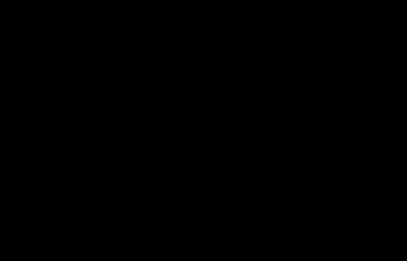
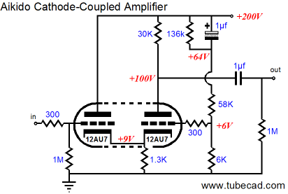
True, the above circuit doesn’t use a constant-current source to load the shared cathodes. True, no large negative power supply rail is used to allow for a large-valued cathode resistor. Still, this cathode-coupled amplifier uses a few tricks. First, the input triode’s plate sees the full B+ voltage without any voltage-dropping plate resistor, which would normally unbalance the triodes DC operating points. But in this circuit, the DC balance is restored by presenting the output triode’s grid with a +6V bias voltage. The two-resistor voltage divider also serves to provide a hint of negative feedback, both AC and DC to the output triode. Now, if you are willing to abide the inclusion/contamination of solid-state devices, then the National Semiconductor LM134/LM234/LM334 3-terminal adjustable current sources are a good choice, as they will source up to 10mA and work with only a few volts across them. Alternately, a FET constant-current source could easily be made up from any FET with an IDSS greater than the desired current draw, as a source resistor will decrease the FET’s conduction to the require value. I, however, would try the simple cathode resistor first, before I tried to fix that which might not be broken. In fact, I would tackle the cathode-coupled amplifier’s poor PSRR first. In other words, get ready for another Aikido moment.
We lost the negative feedback loop, but we added a feedforward noise-reduction system in its place. In a nutshell, the power-supply noise is injected into the cathode-coupled amplifier’s second input, where it is amplified and phase reversed, so that it cancels at the output triode’s plate. The output triode still sees the same 6V bias voltage, so the two triodes will still conduct equally. In SPICE simulations, the PSRR improvement was extreme—an over 40dB improvement; expect reality to differ, but with patience and skill, it can be brought in line with the simulation. The distortion in the SPICE simulation was equally impressive, but then SPICE models are overly optimistic, assuming a perfectly constant amplification factor that does not exist in reality. Nonetheless, I am sure that this circuit would walk all over the original. Well, if that’s true, why don’t I buy an MCD908 and give it a try? Good question. One problem with the MCD908 is that I would not know when to stop. For example, since the line stage amplifier is not really required (the power amplifier easily able to make do without it), why not then use the two tubes for some other purpose, such as a phono stage. See case_riaa_6 for an example. Imagine what a great little system could be made from such a modification: a turntable and an LCD TV monitor and the MCD908. A perfect bedroom system, perhaps. Then there is the issue of replacing inferior parts with better parts. And what of the loudspeakers? What sort of crossover do they hold? Before you know it, a lot of time, effort, and money would find itself pouring into the MCD908. Maybe it would be worth it. I would love to find out.
//JRB
|
Now accepting
High-quality, double-sided, extra thick, 2-oz traces, plated-through holes, dual sets of resistor pads and pads for two coupling capacitors. Stereo and mono, octal and 9-pin printed circuit boards available.  Aikido PCBs for as little as $24 http://glass-ware.stores.yahoo.net/
Now accepting Support the Tube CAD Journal & get an extremely powerful push-pull tube-amplifier simulator for TCJ Push-Pull Calculator
TCJ PPC Version 2 Improvements Rebuilt simulation engine *User definable
Download or CD ROM For more information, please visit our Web site : To purchase, please visit our Yahoo Store:
|
|||


| www.tubecad.com Copyright © 1999-2007 GlassWare All Rights Reserved |