| John Broskie's Guide to Tube Circuit Analysis & Design |
04 February 2008
24V Aikido PCB User Guide
24V Aikido PCB Heater Capacitors—IMPORTANT!
More About the 24V Aikido Line-Stage/Headphone Amplifier PCBs I have to admit that I have always held a slightly unfavorable view of the 6GM8. I just could not imagine that the little 9-pin dual triode could work so well, as I had been convinced of the necessity of high-voltage and high-current. For example, I like running my 12AX7s with 250V on their plates and 1.3mA through their cathodes. Still, Tube CAD Journal readers were building 24V Aikido line stage amplifiers and loving the results. But if Missouri is the "Show-me state," I could be the “Play-it-for-me audiophile." And listening to the 6GM8 has been on my list of things to do for over twenty years. I remember, about a decade ago, a friend called me up to tell me that Antique Electronics Sales (or Fair Radio Sales) was blowing out their stock of 6GM8s for just $1 each. He bought a huge bunch, whereas I bought none. A big mistake it turns out; they are great little tubes.
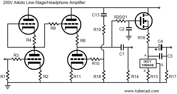
High-Voltage Aikido Line-Stage/Headphone Amplifier
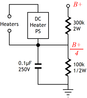
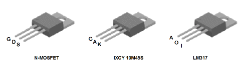
In other words, this arrangement assumes that the heater power supply will be independent from the B+ power supply, which can now greatly exceed the usual 25V limit. Unfortunately, three-pin, solid-state voltage regulators, such as the LM317 or LT1085 are not high-voltage devices. Even the high-voltage version of the LM317, the LM317HVT is only good to 57V. The IXCY 10M45S constant-current source, on the other hand, is a high-voltage device. Thus, the bottom regulator can be replaced with an IXCY 10M45S and the top solid-state voltage regulator, with an additional IXCY 10M45S or any high-voltage, low- wattage, N-channel MOSFET that can be had in the TO-220 package, such as the FQP5N40.
If the heater string and the B+ do not share the power supply, then a voltage relationship must be established between the heater power supply and the B+ power supply. Since one triode stands atop another, the heater-to-cathode voltage experienced differs between triodes. The safest path is to reference the heater power supply to a voltage equal to one fourth the B+ voltage; for example, 75V, when using a 300V power supply. The 1/4 B+ voltage ensures that both top and bottom triodes see the same magnitude of heater-to-cathode voltage. The easiest way to set this voltage relationship up is the circuit below.
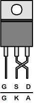
Another problem is that the pinout is not the same for the three-pin voltage regulators and most N-channel MOSFETs and the IXCY 10M45S.
The workaround is to bend and cross over the drain and source leads on the MOSFET and the anode and cathode leads on the IXCY 10M45S.
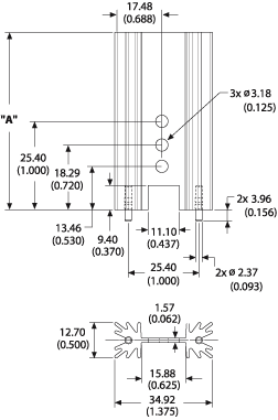
The danger with this fix is that the two leads can short together; not a good idea. The easy solution is to place a short piece of wire insulation or shrink tubing over one lead. So what are the advantages that a high-voltage, MOSFET-based Aikido holds over its 24V cousin? The answer is that many more tubes can be used, for example 6AQ8, 6BC8, 6BK7, 6BQ7, 6BS8, 6DJ8, 6FQ7, 6GC7, 6H30, 6KN8, 6N1P, 12AT7, 12AU7, 12AV7, 12AX7, 12BH7, 12DJ8, 12FQ7, 5751, 5963, 5965, 6072, 6922, E188CC, ECC88, ECC99… A big list compared to the 6GM8, 6N27P, and ECC86. I am not sure about any of the other expected (or imagined) advantages, as the 6GM8-based version is hard to beat. Interestingly enough, the low-voltage version can support a higher idle current through its headphone driver stage than the high-voltage version. This is due to the high-voltage multiplying against the high current and resulting in high heat. The problem with high heat is not so much that the output devices cannot handle it as it is that the heatsinks cannot dissipate quickly enough. The Aavid heatsinks that I used are rated for 5W use, which means that a 24V power supply will allow up to 410mA of current draw through the headphone driver stage, whereas a 100V power supply will only allow for 100mA of current; 200V power supply, 50mA. Speaking of heatsinks, below is the profile of the Aavid heatsinks.
Next Time //JRB
|
Now accepting Support the Tube CAD Journal & get an extremely powerful push-pull tube-amplifier simulator for TCJ Push-Pull Calculator
TCJ PPC Version 2 Improvements Rebuilt simulation engine *User definable
Download or CD ROM For more information, please visit our Web site : To purchase, please visit our Yahoo Store:
|
|||


| www.tubecad.com Copyright © 1999-2008 GlassWare All Rights Reserved |