| John Broskie's Guide to Tube Circuit Analysis & Design |
09 June 2008
A Few Words on Motivation and Method
Well, once I had begun this loose approximation to a blog, that regret lessened greatly, as my aim was to cull the best of the sketchpad’s contents and post it here—ideally, daily. Obviously, the ideal is only dimly reflected in reality, as constructing and posting a schematic-filled webpage is a pain. So much for motivation, now let’s move on to method. Several times a year I come up with something that I believe worth sharing, but that I don’t believe many will understand cold, plopped on the computer screen. In other words, a bit more history and context is often needed to grasp a new circuit. Although embryology does not partake of ontogeny recapitulating phylogeny, getting (fully understanding) a circuit often requires retracing those circuits that have preceded it. So I might spend up to three postings just to set the stage for the final posting. For example, the Broskie automatic-bias circuit took two postings before I could arrive at the final circuit. Sad to say, but sometimes I do not arrive. For example, the No-Pain/No-Gain, unity-gain circuit never got to where I had planned to go. Why Not? One problem is that I loose track over the weeks. And sometimes I spend so much time answering e-mail on the topic from bright TCJers that I feel like I have already posted the final circuit and my attention wanders off to my latest sketchpad entry. (Similarly, I have read that a fiction writer should never discuss his current project, as this will dissipate some of the tension needed to write. By the way, I once went on a road trip with a novelist. As we drove, he detailed the plot to his latest novel. I didn’t just listen; instead, I kept interrupting him with comments such as, "Although that twist works, wouldn’t it have been much more clever to…" and "Why have the crooks steal the object at all, when they can just pretend that they has succeeded and then extract a bundle to return what was never stolen…" He was a bit shaken by my last suggestion and he asked me, "How often do get ideas like that?" My answer was at least once a day, that when I see a movie see three movies: the actual movie, the movie the director should have made, and the movie I would have made. Crestfallen, he replied, "It took me half a year to come up with that lame twist…" I them told that the more important difference is that he actually finished the novel and that was ten times more important than coming up with clever plot twists. ) Well, with this blog post, I arrive at where I wanted to begin. Remember blog number 140, which was written in response to the new hybrid SE-OTL design that appeared in the May 2008 issue of audioXpress Magazine.
My conclusion was that the amplifier, whatever else its sterling attributes, used the large power tube as only a voltage amplifier and that pseudo-output tube could be replaced by a 12AX7, as the tube did not drive the loudspeaker, the solid-state power amplifier did. Well, my first thought was upon seeing the schematic was: What if the tube did more? What if the tube actually did deliver some real wattage into the loudspeaker? What would such a circuit look like?
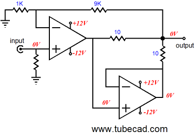
Sharing the Workload Now let’s look into an established method for truly running two amplifier in parallel. Bur-Brown often shows the following topology in its OpAmp datasheets:
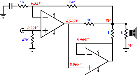
In this topology, the two OpAmps do work equally at driving the load, as each OpAmp delivers exactly half the current, relieving each OpAmp greatly. In fact, the distortion falls off more than one might expect. For example, my guess would have been that, as each OpAmp effectively sees the load impedance doubled in impedance, the same lower distortion and bigger potential voltage swings that a single OpAmp would deliver into twice the load impedance should be realized by two OpAmps in this topology. But if you build the circuit using a single OpAmp and a load impedance twice as large, you find that the distortion is quite a bit higher than the two OpAmps working into the lower impedance. How is that possible? My guess is that the bottom OpAmp is receiving the error correction from the top OpAmp’s output; thus, somewhat supercharging the feedback loop. The downside to this topology is that it requires OpAmps that are unity-gain stable (well at least the one that is wired as a unity-gain buffer). An additional disadvantage is the increased DC offset from the lower OpAmp and the loss across the 10-ohm series resistors. In spite of these negatives, this topology is a godsend for those who want to drive 32-ohm headphones with low-distortion OpAmp, which are too current-limited; for example, the LM4562 or the AD823. Now the question is: How suitable is this topology to a tube-based hybrid amplifier? First of all, making an 8-ohm load effectively appear as a 16-ohm load is not going to make that much of a difference to a severely-current-limited vacuum tube. For example, let’s say that we can get a tube-based OTL to deliver 200mA into the loudspeaker. Well, that 200mA only buys you 0.16W into a 16-ohm load (or effectively a total of 0.64W into an 8-ohm load with both amplifiers working). But then who says the workload must be equally shared between the tube and the solid-state power amplifiers. What if we skew the ratio to 1:10?
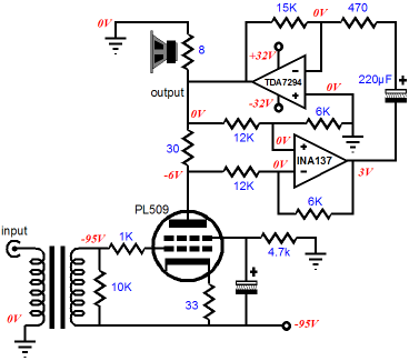
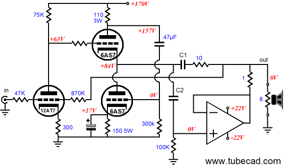
In the schematic above, we see the top amplifier working into a 10-ohm series resistor, while the bottom amplifier works into a 1-ohm resistor before attaching to the external load impedance. Thus, the top power amplifier delivers (8.909V – 8V) /10 amperes of current (90.9mA) into the load; the bottom power amplifier, (8.909V – 8V) /1 amperes of current (909mA), with the total current adding up to 1A into the loudspeaker, which equals 4W of power. Now imagine that the top amplifier is a tube-based OTL and that the bottom amplifier is a gainclone-type power OpAmp, such as the LM12 or OPA541. Let us say that the tube OTL amplifier can only deliver a peak current of 200mA, which would mean that the solid-state amplifier would have to deliver a peak of 2A, with a total of 2.2A of current into 8 ohms equaling 19.3W of average power (38.6W of bogus peak power, which so many high-end audio companies have happily rediscovered). So what would such a hybrid amplifier look like? One possibility is shown below.
First of all, all you die-hard DIYers, who are only interested in usable schematics and not in the least interested in how the circuits work, please put down your soldering irons. The above circuit is still in the conceptual stage, not the finished-and-ready-for-production stage. Note coupling capacitors C1 and C2; these capacitors isolate the tube’s high-voltage from the rest of the circuit and they allow some interesting tweaking. For example, by carefully selecting the values for these two capacitors, we can introduce either a cut or a boost in the low-frequency response of the hybrid amplifier’s output. (Messing up a flat frequency response might seem like an irresponsible thing to do, but refer to it as "voicing" and few will complain.) Also note how coupling capacitor C2 solves the problem of DC offsets from the solid-state amplifier recirculating in a positive fashion. And note how coupling capacitor C1 does not have to be as large in value as I might assume because of the 8-ohm load. Remember that the solid-state amplifier is effectively increasing the load impedance that the tube amplifier sees, which is a bit over 100-ohms, so the capacitor need only be 200µF rather than the 2kµF that the 8-ohm load would seem to imply.
Next Time //JRB
|
Only $9.95
The Tube CAD Journal's first companion program, TCJ Filter Design lets you design a filter or crossover (passive, OpAmp or tube) without having to check out thick textbooks from the library and without having to breakout the scientific calculator. This program's goal is to provide a quick and easy display not only of the frequency response, but also of the resistor and capacitor values for a passive and active filters and crossovers. TCJ Filter Design is easy to use, but not lightweight, holding over 60 different filter topologies and up to four filter alignments: While the program’s main concern is active filters, solid-state and tube, it also does passive filters. In fact, it can be used to calculate passive crossovers for use with speakers by entering 8 ohms as the terminating resistance. Click on the image below to see the full screen capture.
Tube crossovers are a major part of this program; both buffered and un-buffered tube based filters along with mono-polar and bipolar power supply topologies are covered. Available on a CD-ROM and a downloadable version (4 Megabytes). Download or CD ROM E-Mails from two happy customers:
High-quality, double-sided, extra thick, 2-oz traces, plated-through holes, dual sets of resistor pads and pads for two coupling capacitors. Stereo and mono, octal and 9-pin printed circuit boards available.
Designed by John Broskie & Made in USA Aikido PCBs for as little as $24 http://glass-ware.stores.yahoo.net/
|
|||


| www.tubecad.com Copyright © 1999-2008 GlassWare All Rights Reserved |