| John Broskie's Guide to Tube Circuit Analysis & Design |
|
06 August 2008
Inverted Grounded-Cathode Amplifier
It wasn't just the two batteries that confused, but the cathode-follower-looking appearance of the topology. The e-mails asked, "How can there be any gain at all, when this circuit is clearly a unity-gain cathode follower?" (Back in the year 2000, I wrote an article entitled Circlotron Relativity which is—beyond it electronic explication—an exercise in mental flexibility. I recommend that you give this old article a reading to help limber you up for what will follow.) Appearances often deceive. In other words, looking like a cathode follower is not enough to make a circuit be a cathode follower. In the political domain, the question to ask is, Who gains? In an analog electronic circuit, the question to ask is, Where's the input signal's reference located? This referance point is usually the ground, but not always; just as a car's engine is usually located in the front, but not always. Where this referance point is fixed makes a triode function as a grounded-cathode amplifier or a cathode follower in the two circuits below.
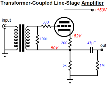
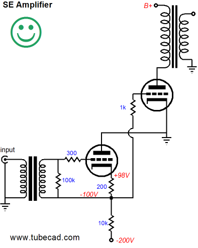
The above circuit is an amplifier, not a unity-gain buffer. The input transformer allows the input signal’s reference to be situated at the amplifier’s output, not ground. Because this reference rides with the output signal, the output swings in phase with the input signal, with gain, with a relatively-high output impedance, and with a fairly-poor PSRR figure. How does it work? As the grid sees (relative to its cathode) a more positive input signal, the triode increases in its conduction, imposing a greater voltage drop across the 5k load resistor, which in turn forces the output to swing positively. Conversely, when the grid sees a more negative input signal, the triode decreases in its conduction, developing a smaller voltage drop across the 5k load resistor, forcing the output to swing negatively. Thus, there is no phase inversion. As long as the load resistor (and the external load impedance in parallel with this resistor) is larger than (rp + [mu + 1]Rk)/(mu – 1), the gain will exceed unity. In fact the formula for gain is the same as the grounded-cathode amplifier: Gain = muR/(R + rp + [mu + 1]Rk), where R is the total load resistance. And the formula for the output impedance is the same as the grounded-cathode amplifier: Zo = R || (rp + [mu + 1]Rk). Aside from the lack of phase inversion, the main difference between the inverted amplifier and the grounded-cathode amplifier is the former's PSRR formula, which is—befitting an inverted topology—the inversion of the grounded-cathode amplifier’s: PSRR = R/(R + rp + [mu + 1]Rk). In the schematic above, the load resistor’s low resistance makes for a better PSRR figure, just the opposite of a grounded-cathode amplifier with the same valued parts. Now, think extremely: imagine a constant-current source in place of the 5k load resistor. What would be the PSRR figure for the inverted amplifier? With a grounded-cathode amplifier, a constant-current source plate load equals an infinite reduction in power-supply noise to the output. But what happens in an inverted amplifier? The answer is that nearly all the power-supply noise bleeds into the output. Now, before anyone jumps to some silly conclusion that the inverted circuit is worthless, let me remind you that in the circuit shown above, the PSRR is twice as good as the comparable grounded-cathode amplifier with the same resistor values, because of the low-ohmage load resistor. Furthermore, never completely discount any circuit, as you never know when you might need its set of attributes and what may seem a liability could prove an asset in a different circuit configuration.
I love getting preachy, which is why I hate doing it. Nonetheless, I have to stress the point that being good at analog electronics is like being good any art form, be it writing, painting, composing, sculpting: you must know as many techniques as you can, but be discriminating. Use only those techniques that work best with each creation. In short, know all you can but be shrewd in applying what you know.
Being a tube guru stands in stark contrast, as the guru knows as few techniques, perspectives, philosophies, and alternatives as he can get away with. He sees it the same way all religious fanatics see it: Why should he waste his time on what is not the one and only true course? The tube guru wants to lead you down his secret path, not show you a Google Earth map of where you are and where you want to go. I wish I had a beer for every time I have been told that the only thing worth listening to was...a Circlotron or cascode or SRPP or balanced or single-ended or push-pull or feedback-free or heavy-feedback circuits, or only 9-pin tubes, octal tubes, RCA tubes, anything-but RCA tubes, DHT amplifiers, Teflon capacitors, PIO capacitors, wet-slug tantalum capacitors, polypropylene-foil capacitors, beeswax capacitors… Back to circuits, both formulas being the same as the grounded-cathode amplifier's makes sense, as the triode has no idea what circuit it is in; it only knows voltage relationships: the voltage differential between its cathode and its plate and between its cathode and its grid. These voltage relationships dictate its current conduction, blindly, unvaryingly. Now in the following circuit, let us move the input signal’s reference point to ground. A 50V battery is used to bias the cathode follower’s grid and the battery, being an ideal battery, offers no AC impedance, so the transformer’s secondary is effectively grounded at one end.
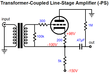
Note how all the DC voltage relationships remain constant, yet this circuit is now a cathode follower, with no gain and low output impedance. The last attribute is worth looking into. Imagine forcing the triode’s cathode more positive by an externally applied pulse. What would happen? The grid would effectively become more negative relative to the cathode and the triode’s conduction would drop, thereby bucking that positive-going perturbation at its cathode, as the 5k load resistor will tug negatively at the output. Conversely, a negative-going perturbation would effectively make the grid more positive relative to the cathode and the triode’s conduction would increase, causing an upward tug at the output. Now apply the same positive and negative perturbations on the inverted amplifier’s output. In both cases the grid would see only a small fraction of the pulse’s magnitude, as input signal’s reference is tied to the amplifier’s output. Because the grid sees almost the same magnitude of pulse as the cathode sees, the triode only responds with a fraction of current conduction swing that the cathode-follower circuit realizes, greatly increasing the output impedance. Before leaving the inverted-grounded-cathode-amplifier topology, I should point out how this topology could work with a negative power supply.
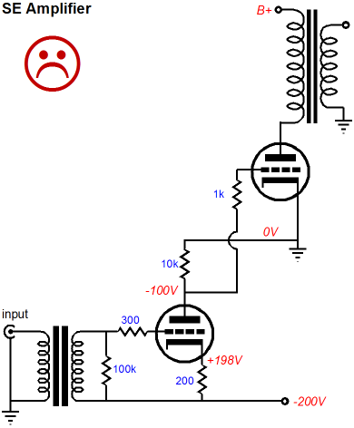
It is interesting, but what good is it? Well, how about this scenario: a low-mu triode, such as the 845 or 6C33 or 6AS7 has its cathode grounded and its plate loaded by an output transformer; its grid directly coupled to a circuit like the one above, but without the coupling capacitor. Now stop and think about why this amplifier would prove much safer than the following.
The answer is that if the driver tube were removed, the output tube would not melt down. The grid falls to -200V in the circuit below, but climbs to 0V in the circuit above. For the same reason, startup is much safer with the inverted amplifier topology; remember, a tube cannot conduct until it’s hot.
Transformer-Coupled Aikido Line-Stage Amplifier
Note the two power supply shunting capacitors that do not terminate into ground. This arrangement ensures that the power-supply noise on the positive and negative rails are related, differing only in phase. Assuming that dual-triode tubes, such as the 6DJ8, 6H30, 6SN7, 12AU7, 12BH7, and 5687, are used and that the triodes are distributed vertically, not horizontally, a single heater power supply can be used, but it must be referenced to -75V, in this example. Now I know that many readers are wondering why an output coupling capacitor is used, as the output seems to be DC-offset free. The answer is that while the DC offset is likely to be close to 0V, it will still be too far off to be safe, particularly with DC-coupled solid-state power amplifiers. Although the simple output-coupling-capacitor is both easy and safe, some will be tempted by the DC servo loop alternative shown below.
The following circuit does away with all coupling capacitors. The OpAmp still monitors the DC offset at the output and its output swings in a contrary polarity, but it does not directly apply a corrective grid bias voltage; instead, it tugs the input stage’s output up and down via the 30k resistor. The two zeners on the output are there as a small safety feature, as they will limit the maximum output swing to roughly +/-6V. This may not seem like much, but it is much better than the potentially ruinous +/-150V.
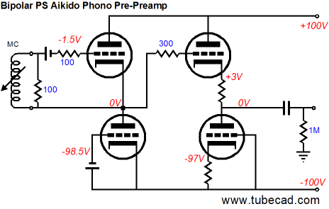
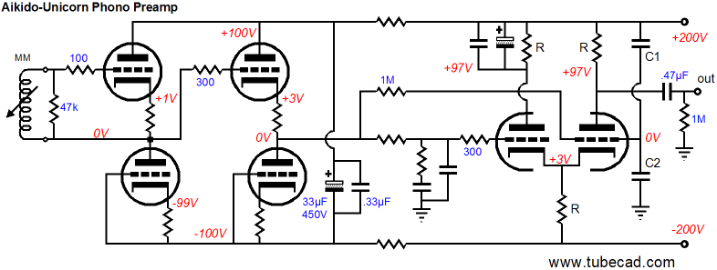
Aikido-Unicorn Phono Preamp
Just to help further establish my non-guru status, I present the above original circuit. Non-guru? If I were a tube guru (or a better businessman) I would never distract you with more phono preamp circuits; instead, I would claim that the Aikido PH-1 phono stage was perfect and that all other phono stages are laughingly inferior. As for the name, Aikido-Unicorn, back in 2002, I wrote an essay titled, RIAA Preamps Part 2, wherein on page 10 the Unicorn topology made its first showing:
// JRB
|
Hi John,
Mr Broskie,
High-quality, double-sided, extra thick, 2-oz traces, plated-through holes, dual sets of resistor pads and pads for two coupling capacitors. Stereo and mono, octal and 9-pin printed circuit boards available.  Aikido PCBs for as little as $24 http://glass-ware.stores.yahoo.net/
Support the Tube CAD Journal & get an extremely powerful push-pull tube-amplifier simulator for TCJ Push-Pull Calculator
TCJ PPC Version 2 Improvements Rebuilt simulation engine *User definable
Download or CD ROM For more information, please visit our Web site : To purchase, please visit our Yahoo Store:
|
|||


| www.tubecad.com Copyright © 1999-2008 GlassWare All Rights Reserved |