| John Broskie's Guide to Tube Circuit Analysis & Design |
| 31 August 2008 UltraPath = Ultra-Simple...Except that it's Not I never liked the question. Why? To start with, the question was always asked in the same manner: excitedly and wide-eyed, an energized agitation worthy of a diehard Star-Wars fan recounting his favorite scenes in the latest installment from George Lucas. Second, the question, when examined closely, reveals itself to be incomplete, empty of a referent or even a context that would make the question answerable. Imagine that you are a chef who is asked, “What do you think about using oregano?” How can your answer make any sense without more context? You might imagine making pancakes, which would provoke a repulsion-filled negative answer; or you might imagine making a Greek salad, which would compel a tongue-salivating positive reply. Since the question, “What do you think about the Ultrapath circuit?” can (like the question about oregano) receive many answers all of which are correct, but conflicting if taken out of context, my standard reply has always been to ask, “What do you think about it?” The answer is usually something along the following lines, “I have never heard it, but I have read that it is a brilliant design and only way to go. I would like to Ultrapath my line stage amplifier, my power amplifier, my phono preamp…but I am afraid that I might blow something up.” What follows is an attempt to provide an overview of the Ultrapath circuit and a context that allows us to understand circuit’s advantages and failings.
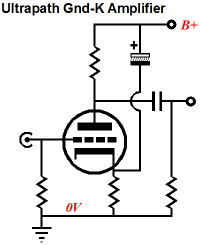
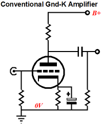
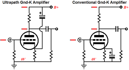
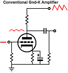
What is the Ultrapath? It is simplicity itself. In the grounded-cathode amplifier above, on the left, we see the Ultrapath circuit; on the right, we see the plain-Jane grounded-cathode amplifier. The "Ultra" comes from having the cathode resistor’s bypass capacitor terminating into the B+ connection, rather than ground, as used by the conventional version on the right. Before examining what shifting the capacitor’s termination yields in electronic terms, just survey the brilliance of Ultrapath. It is breathtakingly simple and it has a mega, supra, ultra-cool name. Very few solder slingers could not master memorizing the Ultrapath’s schematic in five minutes and just as few would not be swayed by its name. Imagine if the circuit had been named the “B-plus-referenced-grounded-cathode amplifier.” Straddled with such a stolid, although accurate name, the circuit would enjoy as much popularity (and sales) as a lite beer labeled “Cheap Beer Diluted with Water.” See Subject: Article Request "UltraPath" for more on this circuit and its ultra name.
How the Ultrapath Works
In fact, so perfectly would the B+ connection mimic ground that the Ultrapath circuit would perform identically to an equivalent grounded-cathode amplifier, yielding no sonic difference whatsoever. In this fantasy world, the Ultrapath would not be so ultra, being jinxed by its requiring a high-voltage cathode-bypass capacitor, rather than the low-voltage capacitor the conventional grounded-cathode amplifier can get away with. In contrast, when using an imperfect power supply, the Ultrapath is also not ultra, but for an additional reason: noise.
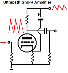
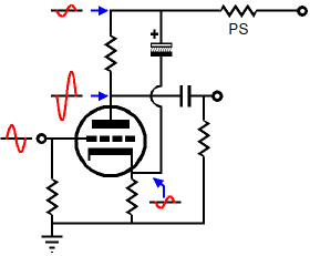
Terminating the cathode resistor’s bypass capacitor to the B+ connection allows the nasty power-supply noise to infect the cathode, which in turn acts as a non-inverting signal input and the triode’s plate sees the power-supply noise amplified and in phase with the B+ connection’s noise phase. The conventional grounded-cathode amplifier, on the other hand, offers a much better PSRR, as the triode’s plate resistance serves to greatly attenuate the power-supply noise at the plate, not amplify it as the Ultrapath does. What? This cannot be right; the Ultrapath is ultra cool and this circuit setup sounds ultra dumb. Besides, a friend of mine Ultrapathed his 12B4 line stage amplifier and it sounds awesome now… So, is the Ultrapath ultra cool or not? I can readily think of three reasons why an Ultrapath-modified line stage amplifier might sound much better than the conventional grounded-cathode amplifier. First the high-voltage capacitor may perform better than its low-voltage brother, just as high-voltage film capacitors sound better than low-voltage film capacitors. A simple test would be to use same high-voltage capacitor in both positions and listen. Second, the power supply may benefit by the added capacitance the Ultrapath cathode capacitor brings, even with the cathode resistor in series with it (and maybe because of the series resistance). For example, if a 10µF main power-supply decoupling capacitor is used, the capacitor’s impedance at 20Hz is about 800 ohms; and the impedance of a 100µF cathode-bypass capacitor at 20Hz is ten times lower at 80 ohms, which even after including the cathode resistor’s added resistance, say 200 ohms, would still be lower than 800 ohms presented by the single 10µF power-supply decoupling capacitor. Third, the Ultrapath cathode-bypass capacitor may do more than just inject power-supply noise; it may also inject some positive feedback. Real-world power supplies present some effective series resistance (ESR), which against the triode’s current variations creates an in-phase signal imposition at the B+ connection, which the cathode bypass capacitor will relay down to the cathode. In other words, the line stage amplifier might develop a bit more gain and exhibit a less flat frequency response—all of which may sound cool. (I have seen grown men titter and giggle with gleeful excitement upon hearing a preamp with a ringing power supply, which imparted a live sound to the music—when the preamp was not howling with high-frequency oscillation.)
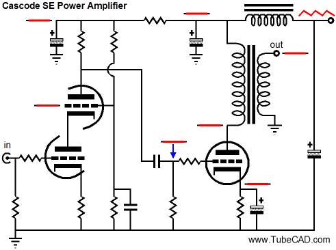
Ultrapath Single-Ended Amplifiers
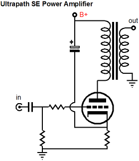
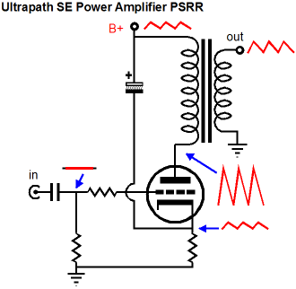
Once again, the same egregious amplification of the power-supply noise pollutes the output signal, as the output transformer’s primary presents an impedance that is fairly flat across the audio band and against which the triode develops a signal gain. Unlike the plate resistor, the output transformer’s primary only transfers the differential across its leads, so a small portion of the power-supply noise gets rejected. Still, the single-ended amplifier below will be ultra noisy.
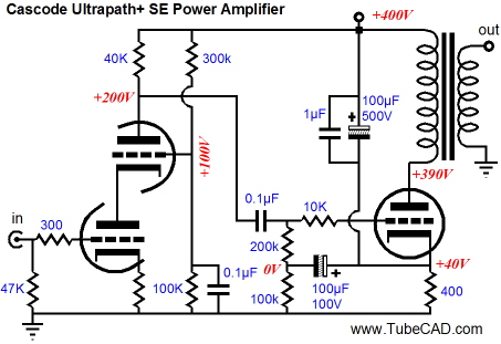
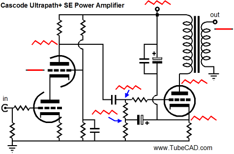
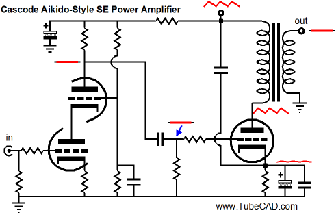
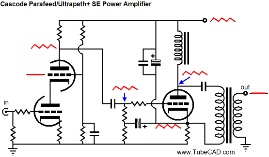
Now, let’s look into the Ultrapath’s advantages. Advantages? Am I being sarcastic? No, just methodical and comprehensive. Let’s start with the single-ended amplifier shown above. The big omission in the above circuit is the input/driver stage, as few can drive a 300B or 845 triode to full power with just their line stage amplifier’s output. Adding an additional gain stage alters many of the power-supply noise relationships with the amplifier. The following examples will use a cascode-based input stage, because the cascode circuit’s vanishingly weak PSRR make the power-supply noise relationships more apparent than a grounded-cathode amplifier would in its stead.
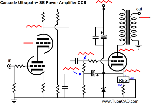
The amplifier shown above consists of two stages, an input and an output stage. The input stage uses two triodes to define a cascode topology, wherein the gain is high, the PSRR nil, and the output impedance close the plate resistor’s value. The “Ultrapath+” in the circuit’s label denotes a slight improvement to the original Ultrapath topology—namely, the addition of the 100µFollower/100v capacitor that couples the power-supply noise to the 200k grid resistor. Why? We want the full power-supply noise to appear not only at the output tube’s cathode, but also at its grid. If this added capacitor were left out, the cascode’s high output impedance would work to voltage divide some of that power-supply noise away with a completely grounded grid resistor.
And we do want all the power-supply noise present at the triode’s plate, grid, and cathode. Once again, an output transformer’s primary only reflects delta, differences across its leads. If the voltage across the primary and the current through the primary remain constant, the secondary cannot “see” the power-supply noise. So what had been the cascode and Ultrapath’s main liability, poor PSRR, has now become an asset. A grounded-cathode amplifier’s better PSRR figure would work against us in this amplifier, as would a grounded-grid amplifier. On the other hand, a pentode-based grounded-cathode amplifier would work as well as the cascode circuit, as the pentode’s super-high plate resistance also results in a truly poor PSRR.
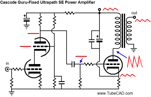
Now, what would happen if we gave the amplifier shown above to a tube guru, with a check for $1,000 plus the price of the parts, so that he could make substantial modifications to the amplifier? Well, he would likely flip when he realized that no RC filter had been employed to provide a cleaner B+ voltage for the input stage. Twelve hundred dollars later ($200 in parts), we would get something like the following.
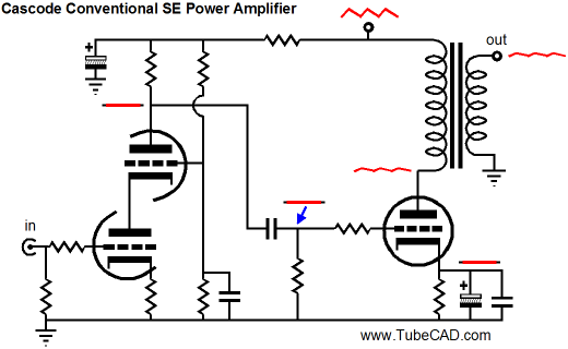
Interestingly enough, the now-fixed single-ended amplifier has much worse PSRR. What should be done? Well, while the tube guru might recommend using Duelund graphite resistors and Mundorf (or Aura-T Teflon) capacitors instead, a better plan would be to remove the added RC filter or to use a conventional cathode resistor bypassing arrangement, as shown below.
Mind you, this amplifier would still be noisier than the original Ultrapath+ single-ended amplifier, as the output transformer’s primary would still see a differential power-supply noise signal across its leads. The Aikido-like fix is the one I recommended back in the second issue of the Tube CAD Journal: add an additional capacitor to the circuit.
The added capacitor bridges the output tube’s cathode to the B+ connection, thereby injecting only a small amount of power-supply noise to the cathode. (In contrast, the Ultrapath injects all of the power-supply noise.) Once again, less is more. The small amount of power-supply noise is just enough to counter the power-supply noise at the plate. As the plate voltage increases, so does the current through the triode; but as the cathode voltage increases, the current decreases. So by setting the correct ratio in place, we can ensure that the triode draws a constant-current at idle, ignoring the power-supply noise as a result, as output transformer’s primary will see a fixed voltage across and constant current through its leads. Now the only question is, How do we find the right ratio? The math is quite simple. A triode’s plate current is set by the following formula: Ip = (Vp – muVg) / rp Solving for ΔVg is not hard, as we have postulated that ΔIp = 0; thus, ΔVg = -ΔVp / mu So for example, a power triode with a mu of 4 would require a change in grid voltage equal to 1/4 the change in plate voltage to keep the triode draw a constant current. the problem here is that we are injecting the power-supply noise into the cathode, not the grid, so a new formula is needed. ΔVk = ΔVp / (mu + 1) The above formula takes into account that a change in cathode voltage is also a change in cathode-to-plate voltage. Using the triode with a mu of 4, the cathode needs to see 1/5 as much of the power-supply noise as the plate does. In other words, the added capacitor’s value must be 1/4 as large as the cathode bypass capacitor’s value. For example, a 100µF high-voltage capacitor and a 400µF low-voltage capacitor would work. As a practical matter, expect electrolytic capacitors to hold more capacitance than marked and film capacitors to hold less. (The sad secret is that with modern high-tech capacitor winding machines, it is extremely easy to get tight tolerance capacitors, which combined with a tradition of 20% tolerance for large film capacitors, makes for a subtle ripoff: capacitor manufacturers can make all their film capacitor consistently low in value, but still well within the 20% tolerance. For example, let’s say that the capacitor winding machine intrinsically delivers 3% tolerance capacitors, so when 10µF capacitors are being made, the machine can be set to 8.5µF and all of the resulting caps will be within 20% of 10µF, saving the company 15% of the materials used. Villains.) In other words, be sure to measure the capacitors and expect to tweak the values to get the deepest noise null.
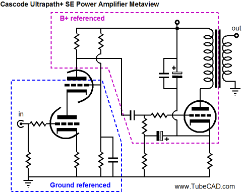
Ultrapath Meta-View*
The input signal is ground referenced, as is the signal source. But once the signal become amplified by the input cascode stage, the signal effectively becomes B+ referenced (because of the cascode’s negligible PSRR). The output stage is entirely B+ referenced, as the output tube’s cathode, grid, and plate see all of the B+ noise and voltage drifts. This dual-reference arrangement can work quite well, as long as we strive to maintain the purity of the two reference territories. In other words, we must mentally block out the two reference domains and work to keep each isolated from the other. For example, if an input stage with much better PSRR were used or if the output tube’s cathode were replaced by a zener diode, the overlap would be huge and amplifier’s performance severely compromised. Now, if a cathode resistor is good in the output stage but a zener is bad, is there a best component for this position? Ideally, a high-impedance device is needed, as it would couple least. A med-DCR choke or constant-current source would be close to ideal.
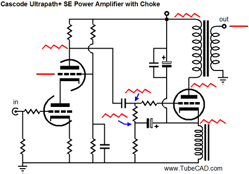
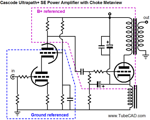
The choke takes the place of the cathode resistor and wonderfully isolates the B+ from the ground.
Note how the choke’s DCR must equal that of the cathode resistor it replaces and note how well the choke breaks the AC connection to ground. The choke, however, does suffer from being large and heavy and expensive; and it, like all reactive devices, does exhibit a frequency-dependent impedance. For example, at 20Hz the choke’s impedance is only 1/1000 its value at 20kHz. Then there is the issue of inter-winding capacitance and core non-linearity. All of which compels looking into using a constant-current source in place of the cathode resistor.
In the above schematic, we see a three-pin low-voltage regulator configured as a constant-current source. The smaller in value the resistor connected to the regulator output is, the greater the current flow. The zener diode should be selected to provide a safety net for the solid-state regulator. In other words, under normal operation, the zener never breaks into conduction; but should the output tube’s cathode voltage try to climb above the regulator’s differential voltage limit, the zener will save the day by clamping the cathode down to a safe voltage.
Before leaving this topic, I should mention that the choke-biased single-ended amplifier is an interesting rearrangement of a more-conventional single-ended amplifier. Chokes are often used in tube power amplifier power supplies as a filter element. In the choke-biased Ultrapath+ amplifier, the choke also functions as power supply filter. In other words, the choke does double duty, working as cathode resistor and as power supply choke.
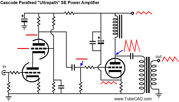
Parafeed and Ultrapath
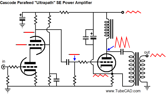
Note how the power-supply noise becomes amplified in the parafeed/Ultrapath amplifier shown above. And do not think that the following amplifier is much of an improvement.
Fixing the amplifier shown above will require disentangling the two implicit signal references, as shown below. (Yes, the output tube's cathode resistor can be replaced by another choke.)
Conclusion Second, no doubt many will shake their heads in disbelief at this blog entry. How could have JRB gotten it so wrong? First it was the SRPP, then the Circlotron, and now the Ultrapath. The Ultrapath is not about PSRR or anything so banal, they will counter; it is a mega ingenious solution to boring tube amplifier sound. And it requires greater metaphysical acumen than JRB posses to grasp its transcendent subtleties, such as drive and short power-supply loops… Well maybe, but the onus is on my opponents to provide some rational explanation of what is going on in a Ultrapath circuit. Surely, it cannot be ultra difficult.
// JRB
*Meta- is a prefix that denotes transcending, as in words like metalinguistics and metamathematics, and it gets its mojo from the word "metaphysics," which in Acient Greek means "after the physics." In the arrangement of Aristotle's works by scholars in the first century, "Metaphysics" was the given title of Aristotle's treatise on first principles only because it, in the pile, followed his work on physics. Had it, instead, proceeded his Physics in the stack, we would have had "prophysics" and "proview." Hmm.
|
High-quality, double-sided, extra thick, 2-oz traces, plated-through holes, dual sets of resistor pads and pads for two coupling capacitors. Stereo and mono, octal and 9-pin printed circuit boards available.  Aikido PCBs for as little as $24 http://glass-ware.stores.yahoo.net/
Support the Tube CAD Journal & get an extremely powerful push-pull tube-amplifier simulator for TCJ Push-Pull Calculator
TCJ PPC Version 2 Improvements Rebuilt simulation engine *User definable
Download or CD ROM For more information, please visit our Web site : To purchase, please visit our Yahoo Store:
|
|||


| www.tubecad.com Copyright © 1999-2008 GlassWare All Rights Reserved |