| John Broskie's Guide to Tube Circuit Analysis & Design |
28 November 2008 Cathode-Coupled Amplifiers
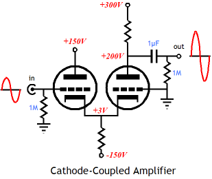
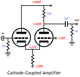
Background Blogs: A few years ago, I received many requests for more information on the cathode-coupled amplifier, but not much interest the last two years. Until, just recently, as two readers have wrote asking for help with their cathode-coupled amplifier circuits and a friend of mine mentioned interest in this circuit in the last two weeks. Is this a new trend or just a coincidence? Has an article appeared in audioXpress that featured cathode-coupled amplifiers? Well, every time I think that I cannot say anymore on a particular circuit, I discover something new to write about; so it is with the cathode-coupled amplifier. The well-designed cathode-coupled amplifier must address the voltage discrepancies between triodes, as one triode sees the full B+ voltage on its plate; the other, the B+ voltage minus the voltage drop across its plate resistor. Two different plate voltages require two different grid-bias bias voltages to maintain the same idle current through each triode. The slacker workaround is just to add an identical plate resistor to the other triode. This resistor must be bypassed by a large capacitor, for if the plate is left swinging, then Miller-effect capacitance is reintroduced and signal gain is lost. The more difficult workaround is to give each grid its own grid-bias voltage. But how can these voltages be ascertained, without having to go through much trial and soldering? A general understanding of how triodes function and some simple math is all that is needed. Let us start with mu, i.e. the triode's amplification factor. The ratio between the triode’s grid over its plate in governing current flow is the triode’s amplification factor. For example, a triode with mu of 10 has a grid that is ten times more effective than the plate in controlling current conduction from cathode to plate. So, if the plate voltage is increased by 10V, the resulting increase in current flow can be countered by making the grid 1V more negative. Therefore, if we know difference in plate voltages between the two triodes and the triode’s mu (assuming identical triodes), we can figure out the required grid voltage difference. For example, given one plate voltage at 300V and the other at 200V and a mu of 10, we divide the 100V difference by 10, getting 10V as the grid-voltage differential. In other words, the input grid will be at 0V and the second grid must be at -10V to ensure the same idle current flow through both triodes.
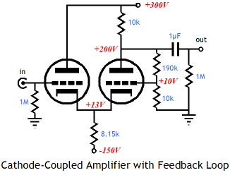
A feedback loop’s voltage divider resistor pair is a source for a free positive voltage source, as shown below.
To be frank, the feedback loop implies a final gain of 20 from the above amplifier, which cannot be realized with a triode with a mu of only 10. So this feedback is more of a DC rather than an AC feedback loop. What do we do if we want to use a feedback loop but it doesn't’t give us the DC voltage split? The workaround is to place the feedback loop after the output coupling capacitor and then add an input coupling capacitor.
Note how the input grid must see a negative bias voltage, whereas the feedback grid saw a positive voltage. Now, here is a sneaky third way to set equal plate currents and yet still use the same grid bias voltages between triodes; add an extra voltage source to the circuit. In the schematic below, we see the lowly 9V battery serving as that voltage source. The battery forces the input triode’s cathode 9 volts more positive than the second triode’s cathode, thereby making the input grid effectively 9V more negative then the second triode’s grid.
The cathode has its own amplification factor, which is equal to mu + 1, which explains why (mu + 1) always seems to be showing up in tube formulas. Note how the input triode sees a cathode-to-plate voltage of 288V, whereas it had seen 297V in the previous example. Thus, adding the battery had not only changed the grid-to-cathode voltage, but the cathode-to-plate voltage as well, which explains why a 9V battery was used rather than a 10V battery. In other words, the input triode lost 9V of cathode-to-plate voltage, so the differential between triodes lessened, which requires a smaller compensation in grid-to-cathode voltage for the input triode. Thus, the formula for cathode bias adjustments is Vdif / (mu + 1); in this example, 100V / (10 + 1), which is about 9V. Ok, I know few readers are pulling their hair right now. “A #@*# battery,” I can hear them muttering. Yes, real batteries are a pain, but this has been a theoretical analysis, not a DIY article. Furthermore, we can use other voltage-displacing devices, such as forward-biased diodes.
Be sure to note the switch to a high-mu triode. Also note how the 1.5V increase in cathode voltage for the input triode is equal to plate-voltage differential divided by 100, the mu of a 12AX7. Of course, either the battery or the diodes can (and maybe should) be bypassed with a quality capacitor.
Next Time
//JRB
|
Kit User Guide PDFs
E-mail from GlassWare Customers And
High-quality, double-sided, extra thick, 2-oz traces, plated-through holes, dual sets of resistor pads and pads for two coupling capacitors. Stereo and mono, octal and 9-pin printed circuit boards available.
Designed by John Broskie & Made in USA Aikido PCBs for as little as $24 http://glass-ware.stores.yahoo.net/
The Tube CAD Journal's first companion program, TCJ Filter Design lets you design a filter or crossover (passive, OpAmp or tube) without having to check out thick textbooks from the library and without having to breakout the scientific calculator. This program's goal is to provide a quick and easy display not only of the frequency response, but also of the resistor and capacitor values for a passive and active filters and crossovers. TCJ Filter Design is easy to use, but not lightweight, holding over 60 different filter topologies and up to four filter alignments: While the program’s main concern is active filters, solid-state and tube, it also does passive filters. In fact, it can be used to calculate passive crossovers for use with speakers by entering 8 ohms as the terminating resistance. Click on the image below to see the full screen capture.
Tube crossovers are a major part of this program; both buffered and un-buffered tube based filters along with mono-polar and bipolar power supply topologies are covered. Available on a CD-ROM and a downloadable version (4 Megabytes). Download or CD ROM
|
|||
.png)
.png)
.png)


| www.tubecad.com Copyright © 1999-2008 GlassWare All Rights Reserved |