| John Broskie's Guide to Tube Circuit Analysis & Design |
|
14 July 2009
Differential Cross-Coupled Circuits I remember building a hybrid electrostatic headphone amplifier back in the late 1980s that ran out of steam. I used low-noise OpAmps and they could only swing +/-13V at their outputs, which was not enough to drive the output tubes to full output. I was sure that I had no options, as everything had been already assembled and I could not easily increase the OpAmp power supply rail voltage. Then the idea of cross-coupling came to me, which saved the day, as it effectively doubled the OpAmp voltage swing.
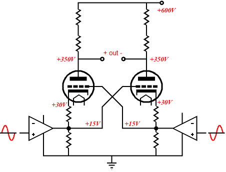
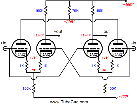
The Van Scoyoc circuit is the most famous example of a cross-coupled differential amplifier. This circuit was created back in 1948 and it gets rediscovered every few years.
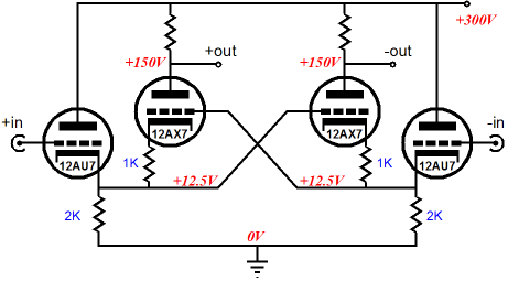
I know why this circuit inspires. It is beautifully simple and symmetrical; in addition, it is DC coupled and it provides more gain that you would expect from a two-triode differential amplifier. So what’s not to like? To start with, the circuit, like most balanced circuits, works best with a balanced input signal, as it makes only a fair phase splitter when one input is grounded. Second, the circuit often develops more distortion than you might imagine from its symmetrical layout. The distortion results from the input cathode follower's having to drive a comparatively low-valued cathode resistor and another triode’s cathode and cathode resistor. Now although a cathode follower delivers a low output impedance, the load impedance cannot be as low as that impedance. In fact, the cathode follower would much prefer a load resistance that was just as big as we would use as a plate resistor in grounded-cathode amplifier, running the same triode and same B+ voltage and idle current—at least twice the plate resistance, in other words. Unfortunately, Rk is usually twenty times less than 2rp. The easy workaround is to use a negative power supply, which would allow for much greater cathode resistor values. Unfortunately, many tube-loving solder slingers hate negative power supplies, something about which most TCJers have no qualms.
Still, I can see how it could be a pain to add a negative power supply to an existing power amplifier that doesn’t hold one. So one workaround is to use dissimilar triodes; for example, the 12AU7/12AX7 combination is a particularly felicitous pairing.
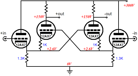
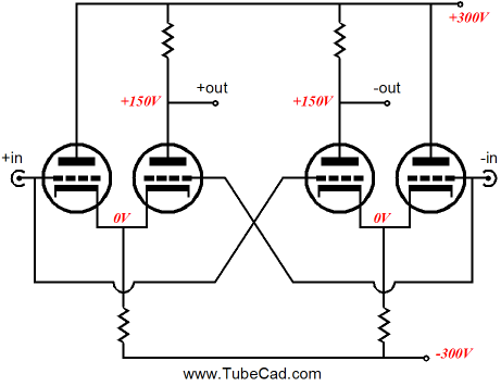
Differential Cross-Coupled Amplifier
If the circuit does not appear obviously simple, try visualizing the circuit as being made up of two cathode-coupled amplifiers fed from a balanced input signal source.
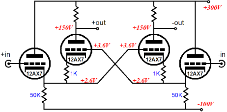
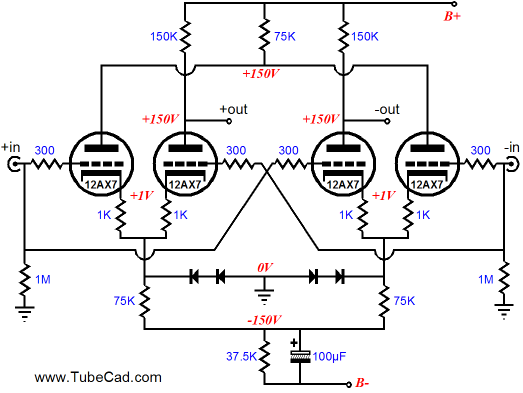
Unlike the Van Scoyoc circuit, this circuit presents a lower input impedance due to the Miller effect capacitance. (This capacitance can be neutralized by cross-coupling small capacitors from plate to grids, but this is only for truly advanced practitioners.) The 1k cathode resistors, which each 12AX7 cathode sees, help linearize the triode and help iron out current draw imbalances due to triode mismatching. One great danger is cathode stripping at startup, when the cathodes are still cold and at -300V, while the grids are a 0V. The workaround is shown below. (I also added my signature PSRR enhancing technique at the final, bottom cathode resistor.)
So how well does this circuit perform compared with the Van Scoyoc circuit? The following table lists the results from SPICE with a balanced input signal of +/-0.1Vpk.
As you can readily see, both circuits offer plenty of gain and low distortion, differential cross-coupled amplifier gain is higher and its distortion lower than the Van Scoyoc; nonetheless, they are both fairly close. Where the differential cross-coupled amplifier really shines is PSRR, but the Van Scoyoc circuit could receive the same Broskie treatment (if it used a negative power supply rail). So, I advise that you add the differential cross-coupled amplifier to your tube circuit recipe book, as it could come in handy one day.
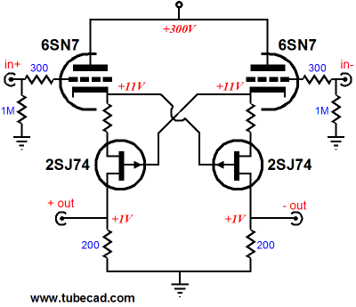
Still More Cross-Coupled Circuits
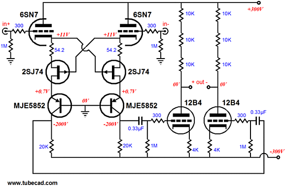
The P–channel FETs limit the current flow through the triodes and should be tightly matched. The circuit's gain is limited by the 200-ohm drain resistors, but the circuit's PSRR is extremely good, as the FET's high drain impedance shield the 200-ohm resistors from B+ noise quite well. Now, let's take this circuit and cascade it. The resulting circuit is an electrostatic headphone amplifier. (A DC-coupled version could be designed, but I would be too intimidated by the high voltages to try.)
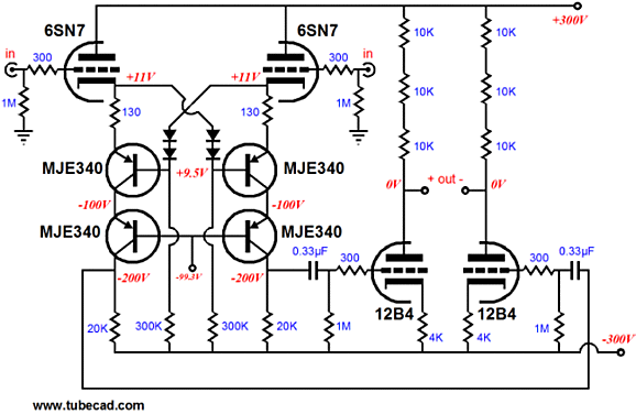
Replacing the rare FET with a commonly available transistor is also doable. The diodes should be the small-signal types, such as the 1N4148, rather than the slow rectifier kind, such as the 1N4001.
CCDA Once Again
On the 9-pin board, I used a pair of 12AU7s and metal-film resistors and polypropylene coupling capacitors; on the octal, new Russian Tungsol 6SN7s and carbon-film resistors and PIO coupling capacitors. Both sound good, but different. The octal version offers a sweet easiness that belies its simplicity and low cost. I know that many long for this type of sound from their systems, as it produces an archetypal representation of what most consider being “tube sound,” but without the usually concomitant hum and power-supply noise.
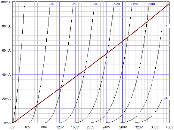
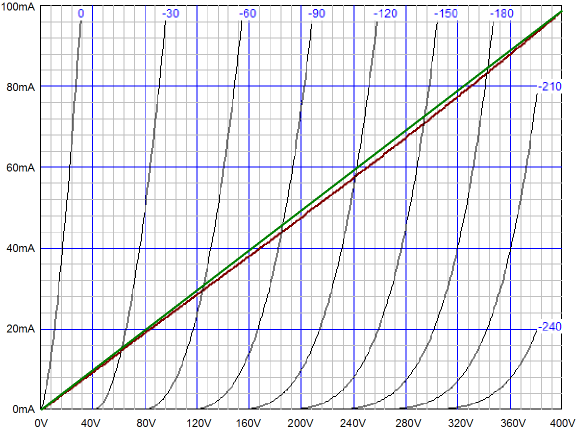
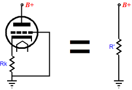
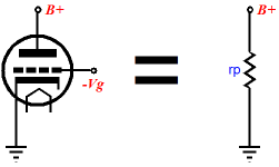
Okay, since I made the CCDA PCBs quite some time ago, why haven’t I started selling them? The big problem that I faced, other than lack of time, was how to make universal kits. Unlike the Aikido, which delivers a perfect platform for tube rolling, as vastly different tubes can be swapped in and out of the board (6AQ8 or 6H30) without having to change the resistor values, the CCDA requires more care in selecting resistor values. For example, a CCDA line-stage amplifier that ran 6CG7s and used 20k plate resistors and 430-ohm cathode resistors could never accept a 6DJ8, 6H30Pi, or 6N1P, as the plate voltage would not center at B+/2, which the CCDA requires. But then, many are not pathological tube rollers; in fact, many do not own thousands of tubes, just a single pair. The still-worrisome problem was, however, assuming the user stuck to one tube type, the daunting array of different possible B+ voltages. For example, that 6CG7-based line-stage amplifier might run a B+ voltage of only 140Vdc or as much as 300Vdc. Assuming an idle current of 7.5mA per triode, a huge array of plate and cathode resistors would be needed. Moreover, the plate resistor cannot be the little 1/2W devices that the Aikido freely uses, but big 2W or 3W power resistors, which are hard to find and expensive. Then it hit me, let the idle current move, but lock the plate and cathode resistor values. A triode with a cathode and plate resistors acts like a resistor, not a perfect resistor, but a fairly good one. Here is a thought experiment: imagine that at the tube factory a resistor was soldered in place within the tube at its cathode and that the only pins, other than the two heater pins, were connected to the other end of the internal resistor and the plate. Now imagine that this odd design were given to a research scientist who set about measuring it. He would find that its current draw varied with applied voltage, much like a resistor, but with some sag in its current versus voltage plot.
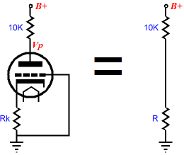
As the graph above reveals, a 6AS7 triode with a 1300-ohm cathode resistor behaves much like a 4k resistor. (By the way, note the much improved linearity over the plate curve lines, albeit at the cost of greatly increased plate resistance and reduced transconductance.) Adding a plate resistor also makes the triode behave more like a good resistor. The formula for the effective resistance is
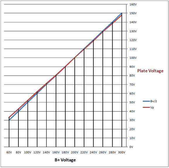
The upshot is that if we chose plate and cathode resistors values to work at the middle of possible B+ voltages, the same resistors will still split the B+ voltage across a wide range of B+ voltages. The following graph was made from actually measuring the midpoint voltage of a 6DJ8 with a 10k plate resistor and a 205-ohm cathode resistor. The results were much better than I ever expected. Plate voltage vs B+ voltage In other words, I do not have to supply huge number of plate and cathode resistors. I am still waiting for some resistors to arrive, but expect the CCDA to be available soon.
Next Time
//JRB
|
Kit User Guide PDFs
E-mail from GlassWare customers:
And
High-quality, double-sided, extra thick, 2-oz traces, plated-through holes, dual sets of resistor pads and pads for two coupling capacitors. Stereo and mono, octal and 9-pin printed circuit boards available. Aikido PCBs for as little as $20.40 http://glass-ware.stores.yahoo.net/ Only $19.95 Download or CD ROM www.glass-ware.com
|
||||||||||||||||||||||||
| www.tubecad.com Copyright © 1999-2009 GlassWare All Rights Reserved |
