30 Dec 2010

Yes, I know that it’s been only a few days since my last post. But I so wanted to reach blog #200 this year, which compels me to post more; in addition, I am super tickled by one of my new PCB designs and am eager to share it with everyone.
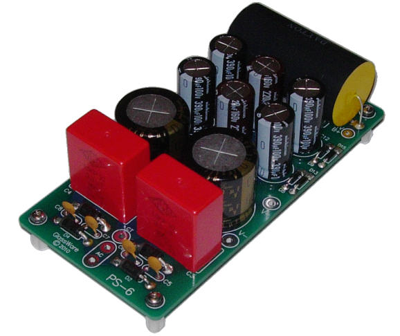
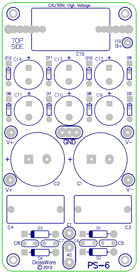
The PS-6 power supply offers a low-voltage bipolar output (up to +/-50Vdc), suitable for solid-state power amplifier or OpAmps; in addition, the PS-6 power supply holds a voltage quintupler that yields a single high-voltage B+ output voltage roughly equal to five times the rail voltage. For example, if the rail voltages are +/-30V, the high-voltage B+ output voltage will be about 147Vdc; if the rail voltages are +/-15V, the high-voltage B+ output voltage will be about 73Vdc. The following is a stripped-down schematic of the PS-6 power supply.
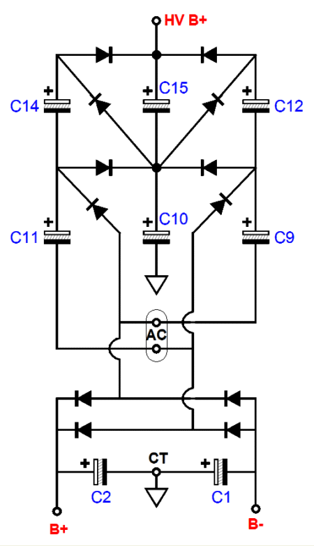
A quick overview. A low-voltage, center-tapped secondary is required, from 10V-0V-10V to 30V-0V-30V. The PS-6 power supply's voltage quintupler uses a full-wave rectification to establish the high-voltage B+ voltage, which explains why there are so many power supply capacitors. As each end of the secondary swings up and down in voltage, the flanking capacitors charge up and spill their accumulated voltage into the center capacitors, C10 & C15. Capacitors C9, C11, C12, C14 and C10, will each charge up to twice the positive rail voltage; in turn, capacitor C10 will charge up to three times the positive rail voltage.
The schematic is missing sevral parts. In series, capacitors C10 & C15 are shunted by a large polypropylene capacitor (30µF/250V). The large low-voltage power supply capacitors, C1 & C2 (3.3kµF/50V Nichicon Audio Grade), are are bypassed by relatively large Wima MKP-10 polypropylene capacitors (3.3µF/160V). Capacitors C9, C11, C12, and C14 each get a shunting rectifier (1N4007) which protects the capacitors from reverse voltages, which will instantly damage an electrolytic capacitor. The ultra-fast rectifiers (MUR410) in the low-voltage bridge rectifier that feed capacitors C1 & C2 are shunted with small ceramic capacitors. (The high voltage rectifiers used to power up the quintupler are ultra-fast HER108 rectifiers.)
The two low-voltage rail voltages are determined by the secondary voltage against the square root of 2 (1.414), minus the rectifier voltage drop (0.6V to 0.8V). For example, given two 22Vac windings (44Vac CT) and 0.7V rectifier drop, we can expect (22Vac x 1.414) – 0.7vdc volts, or 31Vdc, for each rail. (Of course with different capacitors and rectifiers and a higher-voltage transformer, the PS-6 could supply +/100Vdc with a quintupled 500Vdc, which would be excellent for an OTL amplifier, as the output tubes would run on the bipolar 100V rails, while the input and driver circuits would run on 500Vdc.)
Okay, it's nice enough, but what do you with it? Well, I cannot stop of thinking of projects I would like to try, such as hybrid headphone amplifiers, hybrid Moskido power amplifiers, hybrid phono stages, hybrid No-Gain No-Pain line stages... Note the repeated adjective, "hybrid." Tubes love high-voltage and low-current; solid-state devices, low-voltage and high-current. This make the PS-6 power supply a perfect match for these projects. But pure solid-state designs could be made with the PS-6 power supply, such as a tube tester.
In the last year, quite a few novel circuits have appeared here that could make excellent use of the PS-6 power supply. For example, do you remember this super-triode version of a GainClone power amplifier from blog number 179?
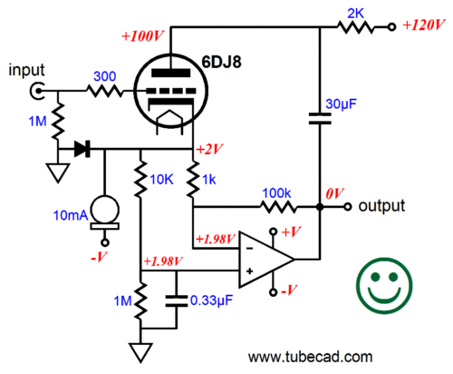
This is not your father's GainClone. The idea behind this hybrid power amplifier is that the triode is in charge of the solid-state chip amplifier, such as an LM1875, LM3886, and TDA2050. The hybrid power amplifier's gain is not the 100 that the 1k and 100k feedback resistors seem to imply, but something a tad less than the triode's mu. A 6DJ8 is shown in the schematic, but many other triodes could be used; for example, the 12B4 might be a good choice for those who do not need a lot of gain.
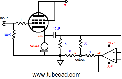
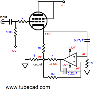
Another interesting design concept was the following hybrid impedance-multiplier circuits from blog number 171.
And then there is the Moskido hybrid power amplifier that weds an Aikido input stage to a unity-gain MOSFET power output stage.
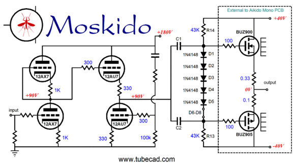
Click on schematic to see close-up
This is the one on which I most want to experiment, as I own several pairs of BUZ901/BUZ906 power MOSFETs. I can easily imagine one Aikido mono PCB and one PS-6 in a monobloc chassis, with two tubes protruding from the chassis and a large toroidal power transformer and fairly massive heatsink at the back. (The heaters would run off the positive 40V power supply rail, with a 100-ohm power resistor in series with the heater string.)
Or, maybe, the TCJ Hybrid SE buffer (from blog number 125) shown below would be a fun project for those who do not need any voltage gain from their power amplifiers. This buffer uses the triode for its brains and the MOSFET for its brawn. (There a better version shown in blog 125, but this topology, as it stands, would work quite well with a sharp-cutoff pentode taking the triode's place in the circuit. I would add a DC servo to the 2A CCS to keep the DC offset low.) 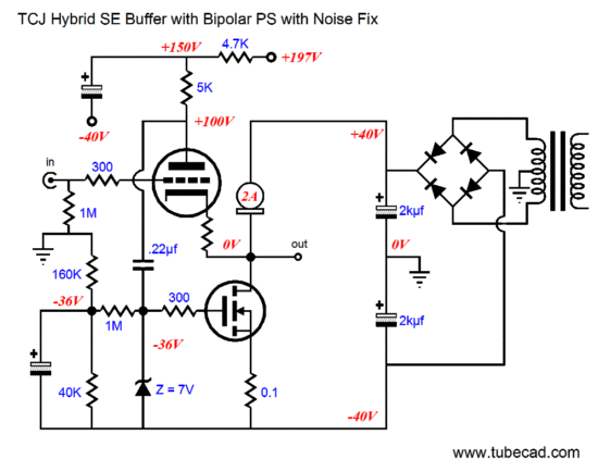
Or how about an OTL line/head-phone amplifier that ran on +/-40Vdc rails? The 6082 dual triode (the industrial verion of the 6AS7 with a 25V heater) would be a perfect choice, as we could run its heater on the low-voltage PS rails. (Or six 12B4s per channel could be used, as one 12B4 will draw up to 30mA, with a cathode-to-plate voltage of 40V; and all six heaters could be placed in string across the bipolar PS rails. And, of course, the output tubes could be replaced with N-channel MOSFETs, which would make a fine OTL power amplifier, as the 40V rails would easily sustain 60W of output.)
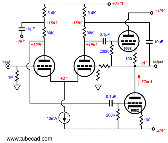
The above schematic shows how a fairly simple low-voltage OTL amplifier could be built. (Imagine a squat 6SN7 paired up with bulbous 6082.) As shown, the circuit is a bit naked, as it is missing the needed grid-stopper resistors and, possibly, a DC servo to keep the output DC free. By the way, getting a second set of lower-voltage power-supply rails to run the DC servo's OpAmp on is easy enough.
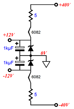
The 6082 heater still sees the required 25V (I like to run tubes with slightly low heater voltages to prolong life and promote greater linearity) and the OpAmp gets its +/-12Vdc rails.
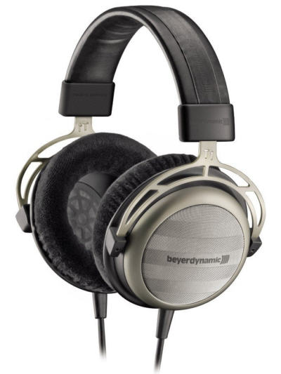
I would to hear the new Beyerdynamic T1 Tesla headphones with this OTL amplifier, as the T1's 600 Ohm voice coil would be a good match with the OTL. By the way, if any TCJer has heard these headphones, let me know what you think of them. I own a Beyerdynamic DT990 Pro and I like it a great deal, so I imagine that the T1 headphones must sound fantastic.
Or how about a hybrid phono stage that made use of a super-quiet OpAmp, such as the LT1115 or AD8599, as the input stage, followed by a passive equalization network, then followed by an Aikido gain stage.
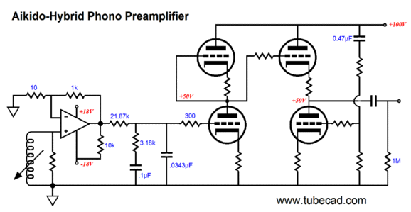
Note how there is only one coupling capacitor. Also note how the phono stage seems to cheat the PS-6 power supply by getting more high voltage B+ voltage than the fivefold rule allows. No cheating is going on here; the +/-18V low-voltage power supply rails are regulated, so the raw power supply rail voltages would be about +/-24V, which would gives us a quintupled B+ voltage of 120Vdc.
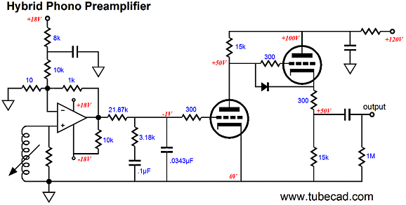
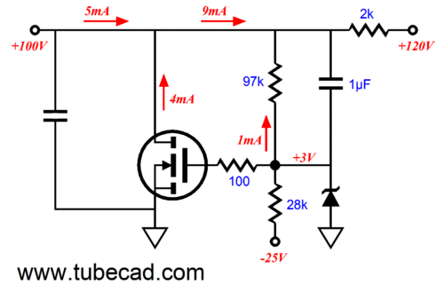
Of course, there are many other possible hybrid phono stage possibilities, such as the following design, which uses only one tube per channel. Note how the OpAmp provides the grid-bias voltage for the input triode, which allows us to lose the cathode resistor. The 18k of resistance that spans from the +18V rail to the OpAmp's inverting input creates a 1mA current flow through the 1k feedback resistor, which in turn creates a -1Vdc offset voltage. The 10k resistor that spans from the OpAmp's negative PS pin to its ouput forces the OpAmp's output stage to run in SE mode.
Surely, one of the most interesting hybrid phono stages that I ever came up with was the Hybrid Grounded-Grid Phono Stage from blog number 118. (Too bad they do not give Noble Prizes for hubris.)

This phono stage employs an Aikido-esque
grounded-grid amplifier. This preamp would only benefit from potentially higher B+ voltage (+97Vdc) afforded by the PS-6's voltage quintupler, assuming a 36Vac CT secondary. An 18V-0V-18V secondary will rectify into roughly +/-25Vdc, which we then regulate down to +/-15Vdc.
No doubt some have grown nervous over the OpAmp getting a regulated power supply, while the tube stage just gets an RC filter. The high-voltage B+ can also be regulated--shunt regulated no less--with the addition of just a few parts.
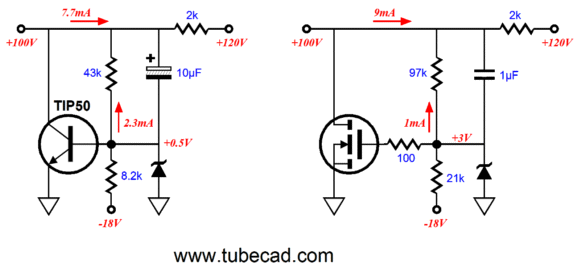
Using either a transistor, MOSFET, or tube, we can exploit the OpOamp's regulated negative rail voltage. The transistor-based version uses different part values from the MOSFET version, because of the transistor's base drawing current. The MOSFET-based version requires a gate-stopper resistor to keep the MOSFET from oscillating. The downside to the shunt regulator is that it must be designed for a specific load current, whereas a series regulator can pretty much ignore the current drawn by the load. One possible problem is big variations in the high-voltage B+, which can easily overwhelm or underwhelm the shunt regulator. For example, if the B+ voltage climbs to 140Vdc, then the shunting device must dissipate up to twice the heat. And if the B+ voltage falls to 100Vdc, then the shunt regulator will shut off. One workaround is to forgo the DC regulation and use an AC shunt regulator instead. In other words, instead of using the regulated -18Vdc as our voltage reference, we use the raw -25Vdc that feeds the negative voltage regulator as the reference. The following AC shunt regulator does not establish a fixed DC output voltage, although it does come close; it does an equally good job of eliminating ripple from the B+ voltage.
The reason this AC regulator almost maintains a fixed DC output voltage is that as the HV B+ voltage moves up, the raw negative power supply rail voltage moves down by the same percentage, so the two-resistor voltage divider (the 97k & 28k resistors) still yields the same output voltage.
Of course, a vastly more complicated shunt regulator, one that used OpAmps and inverted cascode topology, could easily be devised. And who knows, it might actually sound as good as the simpler version ;}
I promised a new phase splitter design and here it is, the Aikido phase splitter. I know that this phase splitter looks like it cannot possibly work, but it does. It functions just like a conventional spilt-load phase splitter, except that the split-load's cathode resistor has been replaced by an active resistive load, created by the bottom triode and its cathode resistor. If we chose its cathode resistor carefully, the impedance presented by the bottom triode's plate will equal that of the plate resistor at the top triode's plate. In other words, nothing much has really changed. But if we feed an input signal to the bottom triode's grid, then things get more interesting. By setting the correct ratio between resistors, R1 & R2, the power-supply noise that leaks into the inverting output will be nulled by the bottom triode's varying conductance.
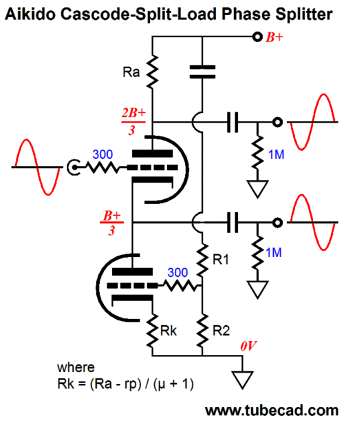
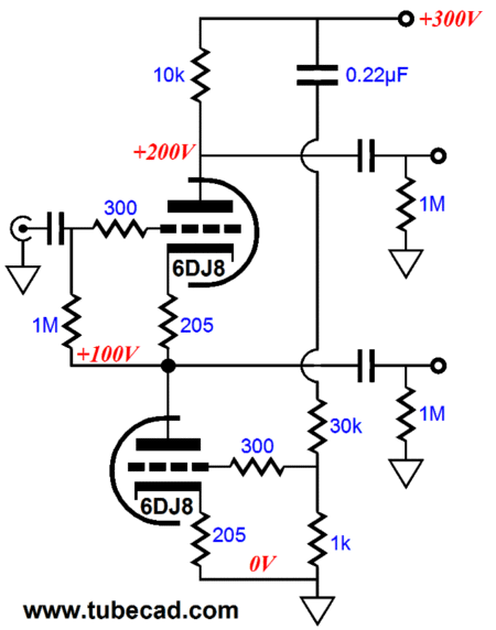
So how do we find the right values for resistors R1 and R2? Resistor R1 should be (mu – 1) times larger than R2. Here is a design example using the 6DJ8/6922.
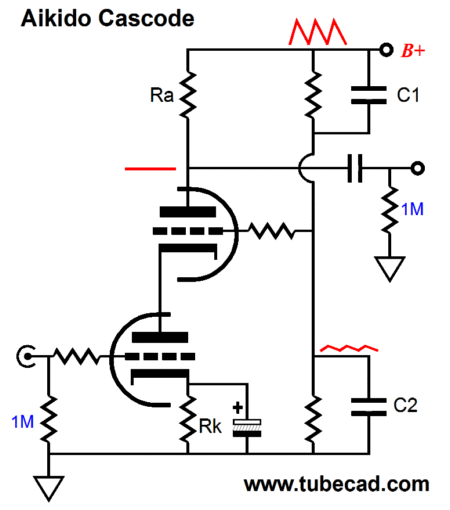
By the way, the first Aikido-esque circuit shown in the Tube CAD Journal was my modification of the cascode, which injected a portion of the power-supply noise into the top triode's grid to null the power-supply noise at the output. This variation on the cascode works in much the same way as the Aikido spilt-load phase splitter does.
Now back to spilt-load phase splitters. What if, instead, we replaced the conventional spilt-load phase splitter's plate resistor with an active load resistance? In other words, what if we replaced the plate resistor with a constant-current source? Would that not greatly improve the PSRR figure of the phase splitter? Wait a minute, John, you cannot use dissimilar loads in a spilt-load phase splitter; is that rarified Colorado air making you dizzy?
Who said anything about dissimilar load impedances? We can use a constant-current source plate load and still maintain an equal plate and cathode load impedance, as the following circuit makes clear. 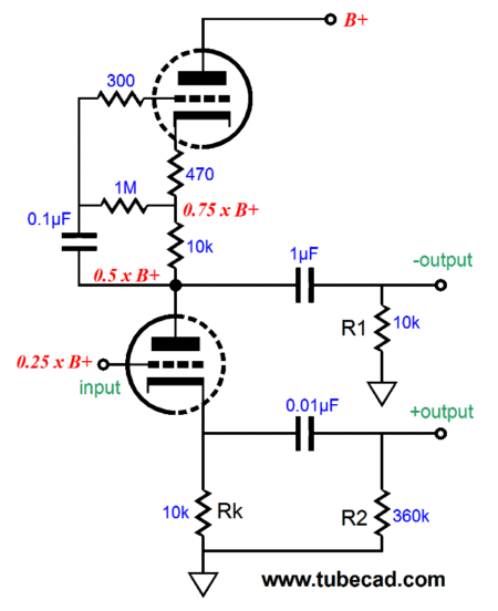
(I have to admit that the implicit symmetry in this phase splitter makes giddy, but never dizzy.) The bottom triode sees 9.73k load impedance at both plate and cathode. The top triode and its associated circuitry creates an effective impedance roughly equal to (mu +1)(470 + 10k) + rp; with a 6DJ8, that comes out to about 360k. Now 360k in parallel with 10k equals 10k in parallel with 360k--or, as my kids like to say, "Duh!" (In other parts of the English-speaking world, they say "dooh-eee" or "doy" or "dur"--choose your own).
In other words, we still achieve wonderful balance. In addition, we make huge gains in PSRR, as very little of the power-supply noise makes it to the inverting (the top) output. Here is the equivalent AC circuit.
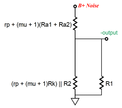
With a 6DJ8, we can expect less than 3% of the power-supply noise to make it to the inverting output. The big problem with this phase splitter is that the top triode's cathode will work at 75% of the B+ voltage, which means that its cathode-to-heater voltage may easily be exceed. Even if we split the difference by referencing the heater power supply to half the top triode's cathode voltage, with a 6DJ8, we must limit the B+ voltage to about 250Vdc.
Also be sure to note the dissimilar coupling capacitor values used. The top coupling capacitor should be 360k/10k times bigger than the bottom coupling capacitor. In other words, I should have shown a 0.027µF capacitor for the bottom coupling capacitor (if only I had an editor).
I have gobs more to say about spilt-load phase splitters, but my fingers are giving out. (Given an infinite amount of time, paper, and pencils, I will come up with an infinite number of circuits.)
//JRB |
|
|
|
Kit User Guide PDFs
Click image to download


E-mail from GlassWare Customers
Hi John,
I received the Aikido PCB today - thank you for the first rate shipping speed.
Wanted to let you know that this is simply the best PCB I have had in my hands, bar none. The quality is fabulous, and your documentation is superb. I know you do this because you love audio, but I think your price of $39 is a bit of a giveaway! I'm sure you could charge double and still have happy customers.
Looking forward to building the Aikido, will send some comments when I'm done!
Thank you, regards
Gary
Mr Broskie,
I bought an Aikido stereo linestage kit from you some days ago, and I received it just this Monday. I have a few things to say about it. Firstly, I'm extremely impressed at the quality of what I've been sent. In fact, this is the highest quality kit I've seen anywhere, of anything. I have no idea how you managed to fit all this stuff in under what I paid for it. Second, your shipping was lightning-quick. Just more satisfaction in the bag, there. I wish everyone did business like you.
Sean H.
9-Pin & Octal PCBs
High-quality, double-sided, extra thick, 2-oz traces, plated-through holes, dual sets of resistor pads and pads for two coupling capacitors. Stereo and mono, octal and 9-pin printed circuit boards available.
Designed by John Broskie & Made in USA
Aikido PCBs for as little as $24
http://glass-ware.stores.yahoo.net/
Only $12.95
to keep track of your
tube and part collection
TCJ My-Stock DB
TCJ My-Stock DB helps you know just what you have, what it looks like, where it is, what it will be used for, and what it's worth. TCJ My-Stock DB helps you to keep track of your heap of electronic parts. More details.
List all of your parts in one DB.
Add part Images.
One-click web searches for part information.
Vertical and horizontal grids.*
Create reports as PDFs.*
Graphs added 2D/3D: pie & bar.*
More powerful DB search.
Help system added.
Editable drop-down lists for location, projects, brands, styles, vendors and more.
*User definable
For more information, please visit:
To purchase , please visit our Yahoo Store:
|