| John Broskie's Guide to Tube Circuit Analysis & Design |
| Post 201 09 March 2011
New Balanced Step Attenuator
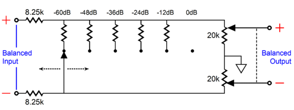
I have wanted to create such a design for a long time, but I couldn't figure out how to make 2-pol/6-pos rotary switches work in a three-switch design. Then it dawned on me that I had come up such a design years ago; unfortunately, I remembered the attenuator sequence backwards. Just as was about to give up, for the third or fourth time, it came to me: instead of using a ladder attenuator cascading into a series attenuator, use a shunt attenuator cascading into a series attenuator. The following schematic shows how this can be done. (Only one channel is shown.)
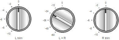
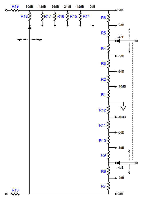
The balanced input signal sees an equal series resistor on each of its phases. Then a 6-position switch selects between no resistor or five resistors to shunt the balanced signal down in amplitude. Each input signal phase sees an identical load, so balance is maintained, no matter what the output attenuation is set. Next, a 2-pole, 6-position rotary switch presents the two phases their own series stepped attenuator, each of which terminates into ground. This arrangement incurs a -3dB insertion loss, but this is a small price to pay for such an elegant solution. I find it essential to be able to make balance-control-like adjustments when listening to old recordings, but not so much with recent recordings.
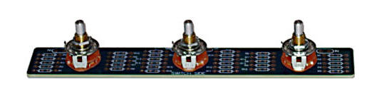
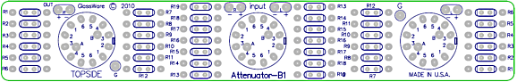
What follows is the same attenuator, but in greater detail. Once again, only one channel is shown. These new B-1 balanced stepped attenuators are available at the GlassWare Yahoo store. They come with and without resistors and they are priced the same as the unbalanced version, even though they hold more resistors.
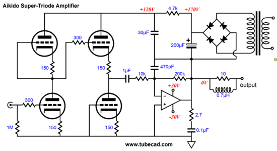
Aikido Super Triode Correction Over ten years ago, I wrote an article titled, Circlotron Relativity, which covered the circlotron power amplifier and many more strange and fantastic circuits that I labeled as being "horizontal." Such as a horizontal cathode follower, horizontal SRPP, horizontal White CF, horizontal cascode... I even showed a single-ended circlotron. The response was, as I remember it, mostly negative, as back then many owners of commercially made circlotron OTL amplifiers were convinced that I was obsessed with dissing their amplifiers (or that I didn't have permission to understand how the circlotron worked); moreover, very few readers thought that my "horizonta"l circuits, such as the following, were possible. Where's the coupling capacitor for God's sake? When I wrote that article, I didn't own a SPICE program, so I had to rely on my conceptual grasp of current flow, which was probably much sounder back then, before having kids, but was still far from perfect. Thus, today, I made a quick check in SPICE to see if I had made any mistakes. I hadn't.
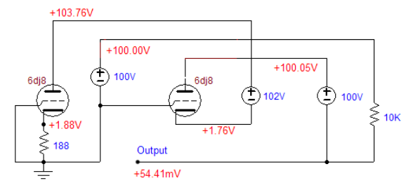
Sure, the cathode resistor value is a bit lower in value and the DC offset is 54.41mV, not 0V, but who says the SPICE tube model is all that accurate; nonetheless, not bad for a bunch of wet gray material—albeit with a platinum patina. (I once took a college class on brain physiology, during which we got to hold and examine an actual human brain; it was surprisingly mushy, in spite of being pickled in alcohol, both it its jar and its owner's skull, which we discovered from brief biography of the deceased and the brain's vodka-altered color and texture.) OK, back to the error in the last blog posting. Here is the circuit:
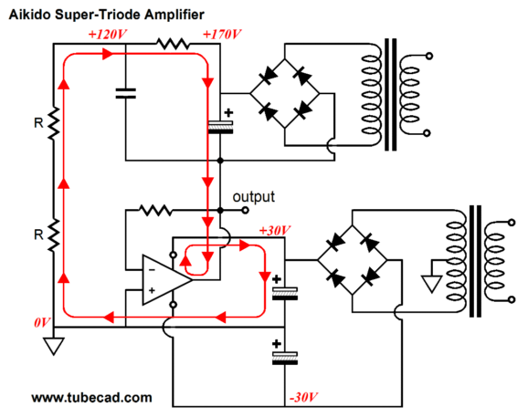
There's nothing wrong with with this schematic, other than being a bit too complex. Now, here is the current path that the electrons take through the tubes and the rest of the circuit, with electrons flowing from negative to positive, as I am just not a conventional kind of guy.
What I like about this arrangement—and which I failed to mention last time—is that the tube's current flow into the solid-state power amplifier's output stage will force a crossover displacement, which will move the output device switchover point away from the zero crossing point, making our ears happier. With the trivial current flow shown in the above example, the displacement will be small, but with different tubes, the displacement could be much larger. Think 6AS7 or 6BX7 or 12B4.
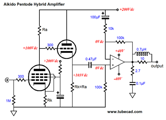
Aikido Hybrid Amplifier
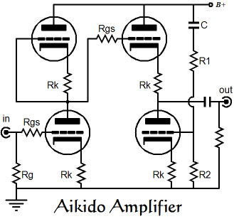
But first, a quick recap on how the Aikido works. The trick behind the Aikido's ability to scrub away power-supply noise is found in the workings of its second stage, a modified cathode follower. This cathode follower uses an active cathode load resistance, which allows us to inject a portion of the power supply noise into the bottom triode's grid, which will allow the bottom triode to function much like a grounded-cathode amplifier, inverting the power-supply noise at is grid at its plate, nulling the portion of power-supply noise otherwise present there . In other words, this sampling of power supply noise forces the bottom triode to vary its conduction in opposition to the noise, nulling the power-supply noise at its output. Because the Aikido's first stage consists of two identical triodes sitting atop each other with identical cathode resistors, the AC voltage division of the B+ power-supply noise is 50%. The Aikido cathode follower, expecting this ratio, creates the required countervailing current conduction to cancel the power-supply noise. Now, if a solid-state power amplifier is to accomplish this same task, it, too, must anticipate the amount of power-supply noise passed by the triode input stage and, then, counterweigh its presence at its output. Achieving this goal is surprisingly easy, but 99% of practitioners of the electronic arts will not like the look of it, as 99.99999% of power amplifier terminate their second feedback resistor into groundoften via a large-valued capacitor, but in terms of AC signal, the feedback loop is grounded nonetheless. This makes perfect sense, as we want the two-resistor voltage divider that constitutes an amplifier's feedback network to cleanly deal out precise and fixed portion of the output signal, so that the amplifier's input stage can use this sampling to compare to the input signal, allowing it to alter its transfer function so that the output may be brought in line with the input signal. And any contamination introduced into this voltage division will sully the results, causing the amplifier to treat the signal contamination as simply just another signal to be amplified. And since ground should be the amplifier voltage reference, it seems the only logical termination for the feedback resistor string. Indeed, there's no argument from me here...except when the input signal is already contaminated, when the signal has already been debased, polluted, infected by power-supply noise. In this situation, a perfect power amplifier would only perfectly amplify the leaked power-supply noise at its output. As they say in the computer world, garbage in, garbage out.
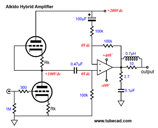
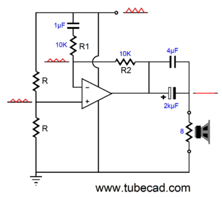
Same amplifier, but with bipolar power supply.
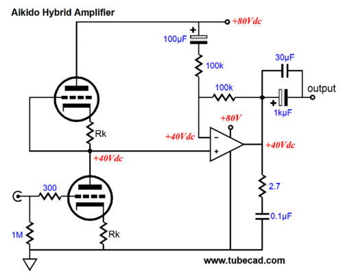
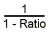
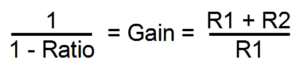
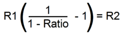
Thus, I have terminated the final feedback resistor into, rather than ground, the B+ connection. This is half of what is required to make an Aikido hybrid amplifier; the second half is to set the amplifier's AC gain to 2 (+6dB). A gain of 2 is required because the two triodes in the input stage define a voltage divider of 50%, so half the power-supply noise will appear at the solid-state power amplifier's non-inverting input, which can only be mirrored at the amplifier inverting input if the feedback resistor pair is terminated in 100% of the power-supply noise and the output is power-supply noise free. The formula for finding the required gain is easy enough, for any given ratio of leaked power-supply noise at the amplifier's non-inverting input, the amplifier's AC gain must equal:
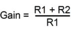
The amplifier's AC gain is set by the ratio between the two feedback loop resistors:
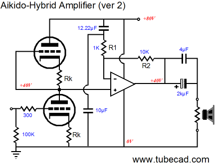
Now we are getting closer. Most gainclone amplifier chips are internally compensated for gains equal to or greater than 10, which means that they cannot be used with fixed gains of 1.33 or 2, but must be allowed to develop gains at least equal to 10. Thus the above circuit could use an LM1875 or LM3886 power amplifier. The big problem is that we now have way too much gain, as the pentode input tube will deliver a gain of (at least) 10 all by itself, which multiplied against the solid-state power amplifier's gain of 10 yields a final gain of 100 (+40dB), which is screaming high. The same holds true for the typical cascode input stage: too much gain. (I must admit there many wonderful dissimilar tubes that hold a pentode and a triode out there just collecting dust and which cost almost nothing, making this topology more attractive…)
The Aikido Hybrid Workaround
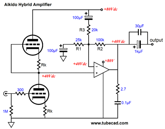
The top feedback terminating capacitor must be 1.222 times larger in value than the bottom feedback capacitor. In contrast, the following Aikido hybrid amplifier can use off-the-shelf 30% capacitors with no ill effects.
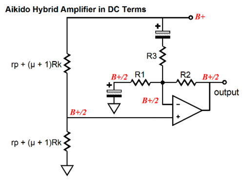
(Before anyone is tempted to ask, a bipolar power supply could just as easily be used.) Let's examine the circuit in DC terms first. Note how the two input triodes equal two identically-valued resistors that split the B+ voltage in half. Note how the solid-state power amplifier's output sits at half the B+ voltage, as the two capacitors allow the solid-state amplifier to use all its considerable DC gain to drive its feedback loop, keeping its output in line with its input.
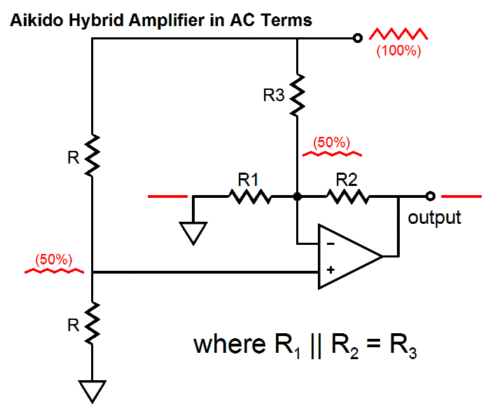
Now, let's look at this hybrid amplifier's AC relationships.
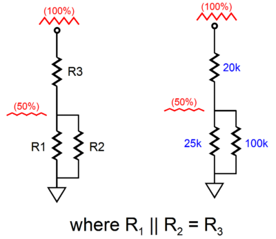
Note how 50% of the power-supply noise appears at both of the solid-state power amplifier's inputs and how no power-supply noise makes it to its output. This ideal situation can only obtain if resistors R1 in parallel with R2 equals resistor R3. In this example, 25k || 100k = 20k, which is R3's value. Another way to look at it—the way I saw it when I came up with this technique, in fact—is to ignore the power amplifier and imagine the following circuits.
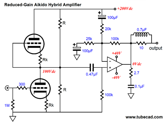
No doubt that many are scratching their heads right now, trying to figure out the AC gain of solid-state power amplifier. Finding its value is not difficult, once you realize that the resistors R1 & R3 are effectively in parallel with each other, yielding a resistance equal to 11.11k. This effective resistance plugged into our earlier formula, (11.11k + 100k) / 11.11k, results in a gain of 10. Almost magic. Don't you think? We lose the noise and establish the required gain at the same time. Very interesting indeed, but haven't I forgotten the problem of too much gain, as the solid-state power amplifier will be multiplying the tube input stage's gain by 10? The answer is to use two very low-mu triodes, such as the 12B4, which would develop a gain of only 3.5 or so, which against the power amplifier's gain of 10 equals a final gain of 35, which isn't too high for most setups, as the average power amplifier usually run a gain of 20 to 30.
Another approach to deal with too gain would be to use medium-mu triodes, such as the 12AU7, 12BH7, ECC99, and 5687, but place a load resistance in parallel with each triode, say two 20k resistors, which will serve to bleed off some of the triode's transconductance, reducing the gain from the first stage.
Next Time
//JRB |
I know that some readers wish to avoid Patreon, so here is a PayPal button instead. Thanks.
John Broskie
E-mail from GlassWare Customers
High-quality, double-sided, extra thick, 2-oz traces, plated-through holes, dual sets of resistor pads and pads for two coupling capacitors. Stereo and mono, octal and 9-pin printed circuit boards available.  Aikido PCBs for as little as $24 http://glass-ware.stores.yahoo.net/
Support the Tube CAD Journal & get an extremely powerful push-pull tube-amplifier simulator for TCJ Push-Pull Calculator
TCJ PPC Version 2 Improvements Rebuilt simulation engine *User definable
Download or CD ROM For more information, please visit our Web site : To purchase, please visit our Yahoo Store: |
|||


| www.tubecad.com Copyright © 1999-2011 GlassWare All Rights Reserved |