| John Broskie's Guide to Tube Circuit Analysis & Design |
| Post 204 26 April 2011
Time for a quick parts update. I have been playing the game of part catch up lately. Many of the parts I buy come from Japan and they seem to be harder to get these days, no doubt mostly due to buyers like me panicking about future part shipments being cancelled because of the recent earthquake, which compels us to try to hoard the parts; thus creating the shortages we wished to avoid. I hate overstocking parts and I hate running out and waiting for the shipments to arrive. The big problem I face is dealing with the regular irregularity in sales. (If I only sold one or two PCBs, life would be so much easier. How I envy those with less imagination. As Nietzsche so wisely put it: "One is best punished for one's virtues.") In many ways, my selling of GlassWare PCB and kits is much more like running a restaurant than an appliance parts supply store. How so? Unless your washing machine breaks down, you are not going to buy a replacement part. There are no wild swings in part sales at the appliance parts supply store. A restaurant can go weeks without cooking some item on its menu; then after a rave review of the item in the local paper, the restaurant can instantly sell out of it. So it is with my menu items: certain PCBs languish on my shelf, then in a few days they are all bought. Often, all the boards go to many different customers living in just one city, which inclines me believe that the first customer has a lot of audiophile friends or an audio club held a sonic shootout. Ok, back to my own parts. I also have new production run of PCBs lined up, which will include the octal Aikido LSA/HPA and octal mono PCBs. I also have new products available now, such as the following attenuator.
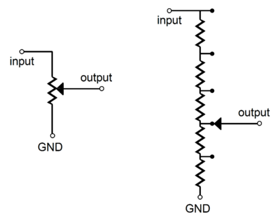
New Mono Step Attenuator Why use a stepped attenuator? The stepped attenuator is an elaborate attempt to overcome the liabilities of the conventional potentiometer-based volume control, as even the best potentiometer compromises the quality of the signal that flows through it. Where the stepped attenuator uses solid, high-tension switch contacts and many tight-tolerence resistors, the potentiometer uses a low-presure metal scraper against low-tolerence conductive paint. So why are potentiometers found in 99.99% of audio gear? Cost. Potentiometers can bought for very little compared to a good stepped attenuator. What is a series attenuator? The closest analogy to the series attenuator is a normal audio-taper potentiometer used as a volume control in 99.99% of audio gear. It consists of a rotary switch that holds many differently-valued resistors placed in series, creating a long chain of resistors, with each resistor connection attached to a switch contact. The rotary switch’s moving contact then selects between resistor connections, thus providing a selectable amount of fixed signal attenuation. The chain of many fixed resistors wired in series defines the total input resistance of the attenuator. This is simple enough, but not without some problems. Where the conventional potentiometer has only three solder joints, these stepped attenuators have as many solder joints as there are steps (+1).
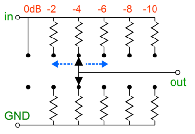
Thus, we have swapped a little conductive paint for a lot of lead and tin. In addition, if one of the resistors is sonically poor sounding it will always make itself heard as all the resistors see all of the signal current, since they are all in series. (Remember the childhood game of passing a secret from one child to another until the secret returns to the author in a completely unrecognizable form.) In other words, the series attenuator works best when it doesn’t hold too many steps. How many is too many? As with all things analog, there is no specific answer, yet we can absolutely know that each additional step will add some miniscule sonic degradation to the signal. What is a ladder attenuator? Perhaps you have seen the small fixed attenuator plugs that hold one male RCA plug and one female RCA jack and two fixed resistors inside a small barrel; these fixed attenuators are useful when bi-ampping and one of the amplifiers offers too much voltage gain. Now, imagine an array of these fixed attenuators and some means of selectively swapping the right one in place. In other words, the ladder improves upon the series attenuator by setting up an array of many two-resistor voltage dividers and the means to switch to the desired pair. Now we are back to just three solder joints and just two resistors in the signal path—but at the cost of twice the switch contacts and twice the resistors used. This is the no-compromise approach to stepped attenuator design. The downside to this attenuator topology is that twice as many resistors (-2) and switch poles are needed. In other words, a comparable series attenuator will cost roughly half as much as the equivalent ladder attenuator.
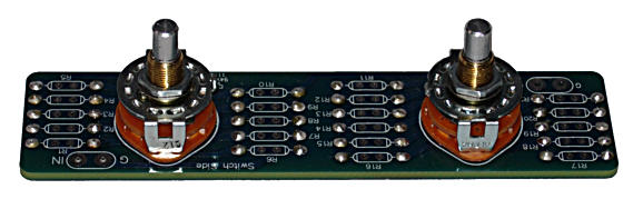
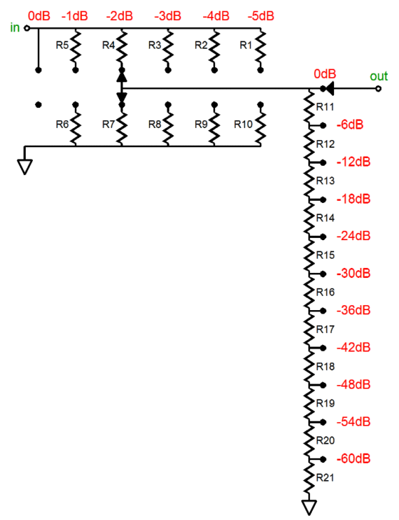
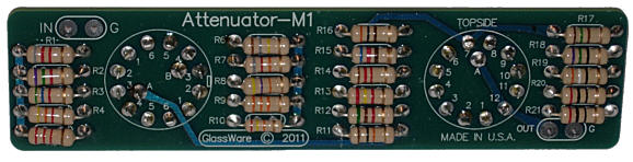
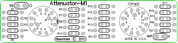
What is a GlassWare M1 mono stepped attenuator? The M1 stepped attenuator combines both series and ladder stepped attenuators into a single functional attenuator. The ladder attenuator's job is to provide six fine steps of attenuation, each step being -1dB; the series attenuator, eleven coarse steps of attenuation, each step being -6dB. The result is that 66 attenuation settings are possible. In other words, we can set the attenuation to any value from 0dB to -65dB in -1dB decrements. The genius of the design is that it only requires two inexpensive rotary switches, instead of one 66-position, insanely expensive rotary switch, assuming that a 66-position rotary switch is even made. In Addition, the GlassWare M1 mono stepped attenuator only uses 21 resistors, not the 66 resistors that a series attenuator would require or the 130 resistors demanded by the ladder attenuator.
The ladder attenuator portion of the M1 takes account of the series attenuator's load impedance, so the M1 always presents a fixed load impedance to the signal source. Because the M1 mono stepped attenuator offers such small volume adjustments (1dB), two of these mono attenuators effectively create a balance control, as each channel can be tweaked in 1dB steps to restore balance.
The PCB is 1.4 by 5.8 inches big and the rotary switch spacing is 3 inches. The price for the M1 attenuator PCB and two rotary switches is $19 USD and a package of 21 resistors is $5.
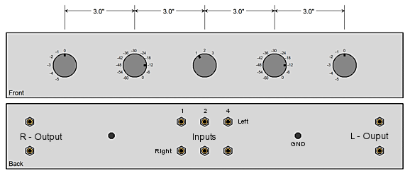
M1 Mono Stepped-Attenuator Applications I myself plan on building a passive linestage out of two M1 mono stepped attenuators and one of my Select-1 3-position signal selector switch.
A 17 by 3 by 7 inch Bud aluminum box and 10 RCA jacks and a grounding post and a three-position, two-pole toggle switch on the back of the chassis is needed to complete design. The right channel's M1 PCB will be rotated 180 degrees, so that two coarse volume adjustment knobs will bookend the selector switch at the front panel's center; symmetry demands it. Why so many ouput RCA jacks? I always use two sets of output RCA jacks, so bi-ampping and subwoofer headphone amplifier setups are easier to implement. The three inputs are situated in the center of the chassis's back panel. Wiring should prove easy enough, with no lead extending more that 10 inches.
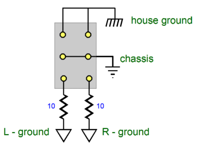
Back of toggle switch
The ground post will attach to the house ground and the toggle switch will choose between electrically floating the chassis or attaching the chassis to the house ground or to two 10-ohm resistors that connect to each channel's ground connection. I will use 20k as the attenuator load impedance and I plan on using 1W carbon-film resistors throughout, although I am sure that most solder-slingers would opt for 1% metal-film resistors. My first guess is that such a project should take about 1 hour to complete, so it should be actually doable in about 5 hours.
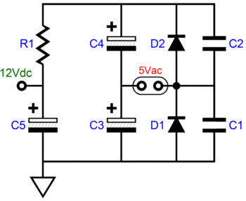
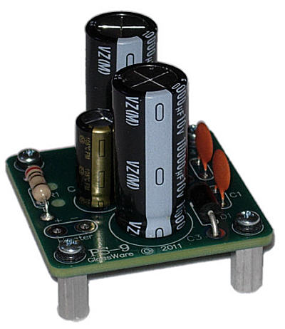
PS-9 New Heater Power Supply
The circuit is a simple voltage doubler that converts the 5Vac into 12Vdc for the power amplifier's frontend circuitry. It is not that big a deal, but once you have point-to-point wired a few of them, you begin to long for a tight little PCB. An absolute steal at $9.95; well, at least I would gladly pay that for the tidiness it would impart to the inside of my power amplifier, besides the parts are first rate (Pansonic FM series and Nichicon 10kµF 105° capacitors, ultra-fast MUR410G rectifiers, and four sets of standoffs).
Next Time
//JRB |
I know that some readers wish to avoid Patreon, so here is a PayPal button instead. Thanks.
John Broskie
Kit User Guide PDFs
E-mail from GlassWare Customers
High-quality, double-sided, extra thick, 2-oz traces, plated-through holes, dual sets of resistor pads and pads for two coupling capacitors. Stereo and mono, octal and 9-pin printed circuit boards available.  Aikido PCBs for as little as $24 http://glass-ware.stores.yahoo.net/
Support the Tube CAD Journal & get an extremely powerful push-pull tube-amplifier simulator for TCJ Push-Pull Calculator
TCJ PPC Version 2 Improvements Rebuilt simulation engine *User definable
Download or CD ROM For more information, please visit our Web site : To purchase, please visit our Yahoo Store: |
|||


| www.tubecad.com Copyright © 1999-2011 GlassWare All Rights Reserved |