| John Broskie's Guide to Tube Circuit Analysis & Design |
|
Knowledge & Understanding Mindless consumerism and mindless materialism are just that: mindless. To be mindless requires not that our mind be empty, but that our heads fill with intense feelings and powerful willing, so that our thoughts entangle with desire, greed, fear, hope, and ignorance. To be mindful, in sharp contrast, requires knowing, thinking, and understanding. Perhaps you will never hear, let alone own, a current-output amplifier. But knowing how a current-output amplifier functions and what its design goals are helps you better understand voltage amplifiers—how they function and what their design goals are. For the current-output amplifier is, in many ways, the inversion of the voltage amplifier. The following chart list four types of possible amplifiers, the conventional voltage-to-voltage amplifier, the voltage-to-current amplifier, the current-to-voltage amplifier, and the current-to-current amplifier. The chart assumes perfect representatives of each type of amplifier; thus, for example, the voltage-to-voltage amplifier should present an infinite input impedance and zero output impedance, although neither will ever be encountered in reality.
Blog post number 98 holds a short section worth re-reading titled, Living in a Voltage-Centric World, which explores the different perspectives entailed by making voltage or current primary in our conceptual framework. Perspective—the mental view or outlook or, finer still, the ability and conceptual framework required to perceive things in their actual interrelations and in their comparative importance—is all important. Our perspective is what we overlay upon existence and we usually take a dim view of another's perspective. And occasionally, we forget that there can be a different perspective, as such a thing would seem essentially wrong. For example, I know that many fear the current-output amplifier, as they are horrified by the frequency-varying voltage that such an amplifier would develop across a loudspeaker. But is such a fear reasonable? As the celebrated Edmund Burke put it so nicely,
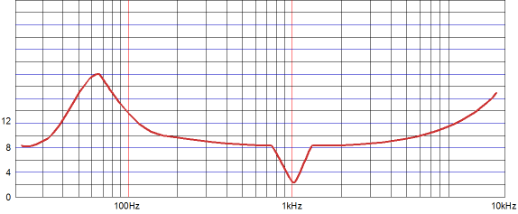
Very few, if any, loudspeakers offer a ruler-flat impedance across the audio band of frequencies, as most present a roller-coaster impedance plot that will, in turn, define a roller-coaster voltage plot across the loudspeaker across the audio band, because of the current-output amplifier's current-specified output. Who would tolerate a non-flat plot of any sort? Audio is part of linear electronics, after all. Mind you, few worry in the least about the voltage-output amplifier's roller-coaster current plot into the same loudspeaker. Why not? Different perspective, different goals, different worries. From the voltage-centric perspective, the varying current does not matter. From the current-centric perspective, its all important. Okay, so which is the right perspective? In other words, what should I believe? Sorry, but that is none of my business. My aim is merely that you, gentle reader, will—by examining the goals and designs issues of a current-output amplifier—better understand the goals and design issues of a voltage-output amplifiers, precisely because of the sharp contrast in perspectives.
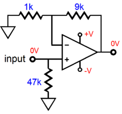
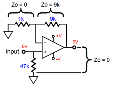
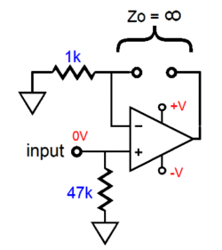
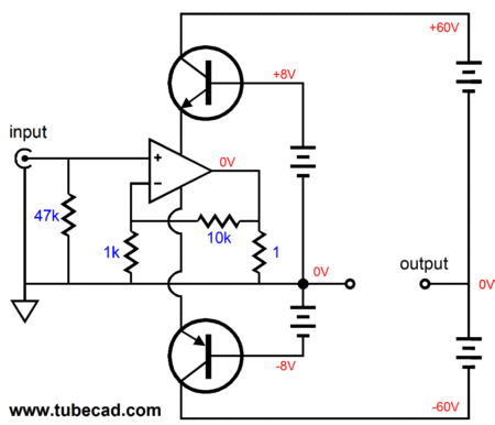
Imagine if the present were otherwise; imagine that, back in 1989, all loudspeaker manufacturers had read Malcolm Hawksford's paper and had created new speaker designs to fully exploit the current-output amplifier; and imagine that such loudspeaker and amplifier pairing were so obviously better sounding than voltage-driven loudspeakers that we all now owned current-output amplifiers, like Nelson Pass's First Watt amplifier. In this inverted scenario, I would be writing about voltage-to-voltage power amplifiers so that we could better understand current-output amplifiers. Speaking of boring, conventional, everyday voltage-to-voltage amplifiers, I wonder how readers have given much thought as to the implicit impedance relationships within the conventional voltage amplifier. The following schematic shows an idealized voltage amplifier that could be made from tubes, transistors, J-FETs, MOSFETs, or something exotic or some yet-to-be-invented devices. The key point to understand is that with zero voltage in, zero volts appears at the output.
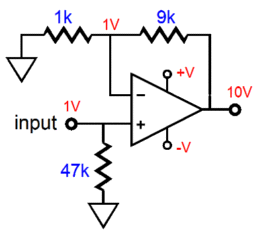
If we present +1Vdc at the input, however, the voltage amplifier will fight to keep both its non-inverting and its inverting inputs in line with each other, so the amplifier's output must climb to +10Vdc.
Thus, we see that the gain (both AC and DC) is equal to (1k + 9K)/1k or 10, which equals +20dB, as gain in dBs equal 20Log(gain). Now, what are impedance relationships within this amplifier? Since we specified an idealized power amplifier, the following impedances must obtain.
Wait a minute, that cannot be right. Why would the impedance across the 1k resistor be zero ohms? And if it were, why wouldn't the impedance across the 9k resistor also be zero ohms, as the output also exhibits zero ohms, effectively shorting the 9k resistor? The answer to the first question is that the amplifier must keep its two inputs in in lockstep, so if a current pulse were injected at its inverting input, the amplifier's output would instantly swing in a countervailing direction to force the inverting input to remain at 0V. Well, what if we used a burly power amplifier, say a 1,000W solid-state monster, and attached its output to the inverting input and forced it to move off zero volts? Sorry, but by accepting the premise of a perfect voltage-to-voltage amplifier, we have precluded the possibility of there also existing some other amplifier burly enough to move its inverting input off zero. Remember the old philosophical question, "What happens when an all-powerful cannonball hits an insurmountable wall?" The question makes no sense, as the existence of either makes the other impossible. In other words, if the voltage amplifier's inverting input could be moved off zero volts, the amplifier wasn't perfect. Or put another way, for the external power amplifier to be able to force our idealized amplifier's inverting input off zero volts would require more than infinite current, as our idealized amplifier can summon an infinite voltage swing and, thus, infinite current through the 9k resistor to force its inverting input to remain fixed. The answer to the second question, "Why isn't the impedance across the 9k resistor zero ohms?" is that we are only measuring the impedance across the resistors leads. The VOM doesn't know that anything else exists. As far as the meter is concerned, there is only the 9k resistor. Imagine that we try to induce a current flow through the resistor, say by wrapping a long strand of wire around its body and that we plug the wire's ends into a wall socket. The induced currents will force a varying voltage, an AC voltage, across the 9k resistor, which is only possible if the amplifier's output presents an infinite impedance and allows this AC voltage to develop unhindered. If it didn't, its inverting input would move off zero volts, which it cannot allow. Okay, so which is it: is the amplifier's output impedance either infinity or zero ohms? Well, confusing as it may seem, it's both. Relative to ground, it's zero; relative to its inverting input, its infinity. Where we place the VOM's two probes makes a difference.
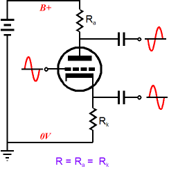
A similar conundrum is encountered when we try to understand the relative impedance within the split-load phase splitter. Are its two outputs the same in impedance or different? The answer depends on where we place the meter probes. See "Zo and Split-Load Phase Splitters" in blog number 167. With meter probes attached to ground and the inverting output:
With meter probes attached to ground and the non-inverting output:
With meter probes attached to both outputs:
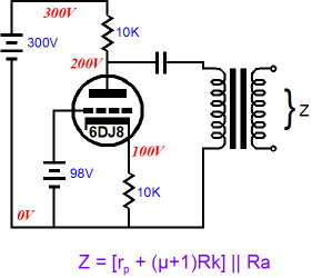
Okay, back to our simple, but perfect voltage amplifier. Relative to its inverting input, the voltage amplifier's impedance at its output is infinity.
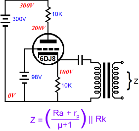
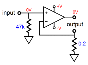
Mind you, such a configuration cannot work, as no current path exists between the amplifier output and its inverting input, so the amplifier cannot maintain zero ohms at its inverting input. On the other hand, if we place the load across the amplifier output and its inverting input, we transform the amplifier into a voltage-to-current amplifier.
This amplifier will define a conversion ratio (a transfer function) of converting each volt of input voltage into 5 amperes of output current, as 1V/0.2ohms = 5A. Thus, 2V in would equal 10A out. And just as the worst-case load for the voltage amplifier is the dead short to ground, the worst-case load for this voltage-to-current amplifier is an open at its output, as a 1V input voltage would prompt an infinite positive voltage swing at the amplifier's output. The workaround would be to use a normally-closed output jack that would complete the current path in the absence of an external load or use a shunting 100-ohm resistor across the output terminals, so the current-output amplifier would have some resistance to bite on and be able to keep its output DC offset minimized. Well, I suppose that this is enough meta-electronics for now, so let's move on to actual circuits.
Simple Hybrid Current-Output Amplifiers
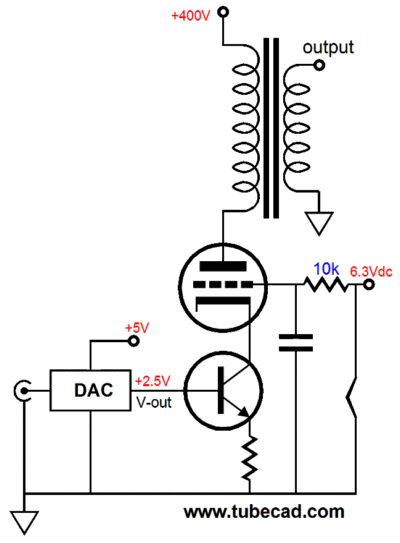
The output tube's cathode voltage depends on the output tube used. With a 300B, the cathode voltage would be about +69Vdc; with a KT100, about 35V. This voltage along with the +6.3Vdc at its grid will bring the 300B to 100mA of current conduction with a B+ voltage of 400Vdc. Okay, why is the grid attached to the 6.3V power supply and just not grounded? The NPN transistors needs some voltage to operate within when the cathode swings down negatively; do not forget that its emitter voltage will climb as the cathode comes down in voltage. How, let's get a bit fancier. Two great advantages the voltage-out DAC provided was the voltage output and the output reference at some positive voltage. The following current-output amplifier also brings its own positive reference voltage.
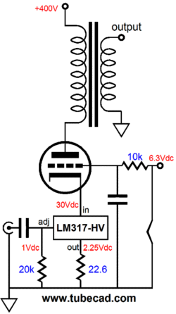
What the…! You cannot use a voltage regulator as an audio amplifier. Wrong. If you think about it for a bit, you will realize that a positive linear regulator is actually half of a single-ended amplifier with a built in voltage reference.
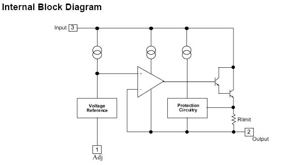
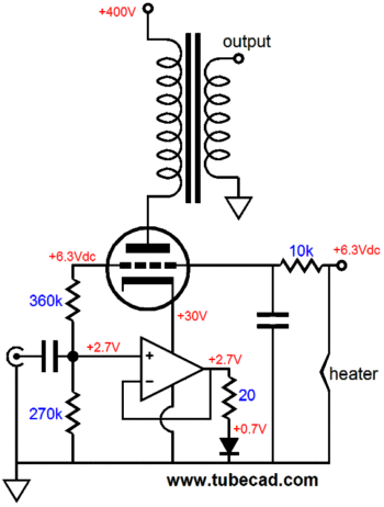
The LM317-HV holds an internal Op-Amp that governs a Darlington transistor output device. If we feed its adjustment pin an audio signal, the OpAmp will work to keep its output in line with the input signal. And since both the regulator and the output tube are in series, any change in the current flow through the regulator will also flow through the output tube and output transformer primary. Note that the LM317-HV's internal voltage reference develops a voltage of 1.25V, but in the circuit above, the output voltage is 2.25Vdc. So where did the extra 1V come from? The regulator's adjustment pin draws 50µA of current, which against the 20k resistor equals 1V at the adjustment pin, which then is added to the internal 1.25V reference voltage, making 2.25Vdc appear at the output. No doubt, many are appalled by the idea of using a linear voltage regulator as an amplifier, so let's move on to using a GainClone type chip, in other words, an IC power amplifier. The great thing about the following design is that the tube powers the solid-state power amplifier at its cathode; I love free power supplies. The amplifier is configured as a unity-gain buffer, which means that most GainClone chip amplifiers will not work, as most are not unity-gain stable, one exception being the L165, which doesn't sound that good. But to be frank, I wasn't thinking of using an LM1875 or LM3886, as the output tube need only swing about 100mA, not 4A. The greatly reduced current swings mean that a wimpy solid-state power amplifier could be used, say a robust headphone amplifier chip or a beefy current-feedback amplifier, such as the LT1210. Note the diode. It is there to raise the 20-ohm resistor up into the voltage-swing capabilities of the power OpAmp; two diodes might be required (and they could be bypassed by a quality capacitor).
And since the amplifier is configured as a unity-gain buffer, why not use a unity-gain buffer, such as the BUF634 or LT1010. Another possible candidate is the LM195, which is a an ultra-reliable power transistor. Yes, I know that you have never heard of it, but you should look into it, as it offers some excellent features. From the LM195 datasheet:
Of course, we could build an all solid-state current-output amplifier. The following current-output amplifier uses a GainClone chip amplifier, such as the LM1875, to drive a varying current through the two power transistors. If the circuit seems to make no sense, just imagine that the output is shorted to ground, then note how the amplifier reduces to an extremely inefficient solid-state power amplifier with a 1-ohm load. Now, imagine an 8-ohm load across the outputs and you will see that the current that flows through the 1-ohm resistor will also flow through the 8-ohm loudspeaker. (I am here assuming that this current-output amplifier is running in lean class-AB.)
Effectively, this impedance is a cascode design, which intrinsically offers an ultra high output impedance. The problem with this amplifier, as it stands, is that the DC offset is not controlled by the voltage amplifier at its center. The workaround would be to use a DC servo loop to keep the output centered at ground potential. Also note that each channel requires its own floating +/-60V bipolar power supply, but that both channels can share the fixed +/-8V bipolar power supply, which could be voltage regulated. Its voltage-to-current conversion ratio is equal to (1k + 10K)/1k or 11 amperes out for every 1V in.
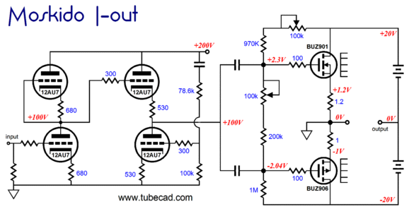
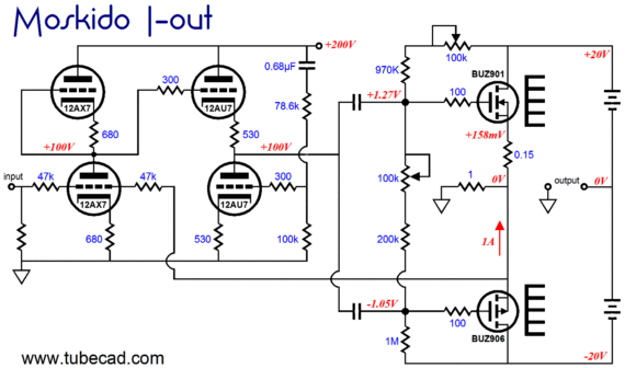
Moskido I-Out Amplifier
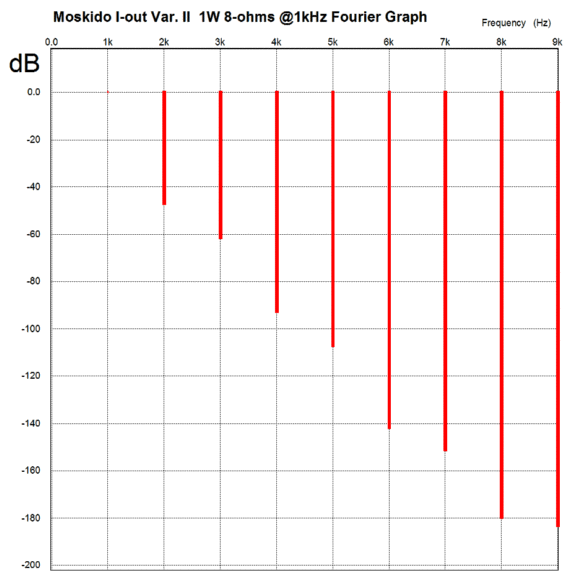
The following graph show a SPICE simulation of just the output stage's distortion harmonic structure.
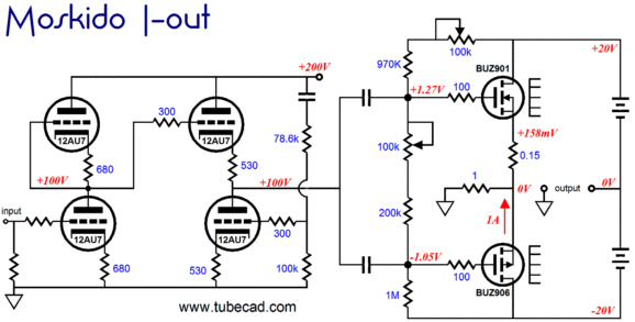
A variation is to use a 1-ohm common source resistor. This resistor only sees a current flow when there is an input signal.
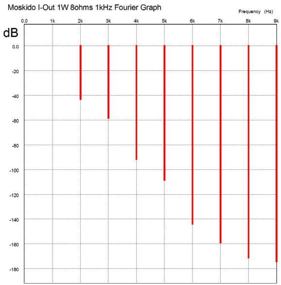
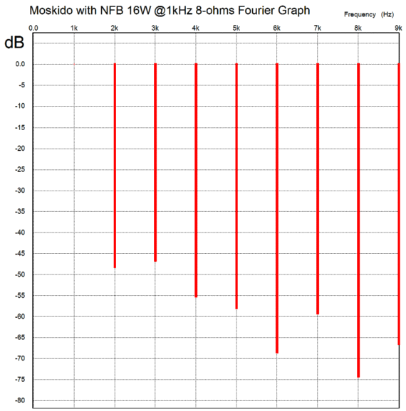
The result of this change is greater output wattage and slightly less distortion, as the following graph shows.
Adding a feedback is easy enough. The feedback loop cannot attach tot he output, as it would convert our current-ouput amplifier into a voltage-output amplifier; instead, we extend the feedback loop to the shared 1-ohm resistor.
Note that the feedback loop is returned to the input tube's grid, not its cathode. Also note that this tube has changed from a 12AU7 to 12AX7. The current-to-voltage conversion ratio is roughly 1V to 1A. The input stage and the output stage both invert the signal's phase, the result is a non-inverting amplifier. Wouldn't it be better to run this amplifier without negative feedback? It depends. If the amp were run in rich class-A, then the feedback would not be essential; in fact, it probably would just get in the way of good sound. On the other hand, if the above amplifier were run in class-AB, with say 160mA of idle current, then the negative feedback would probably be essential, as the distortion would climb and take on a classic push-pull harmonic signature. Here is the SPICE simulation Fourier graph for the above amplifier with 16W into 8-ohm load at 1kHz. The output impedance is about 3700 ohms.
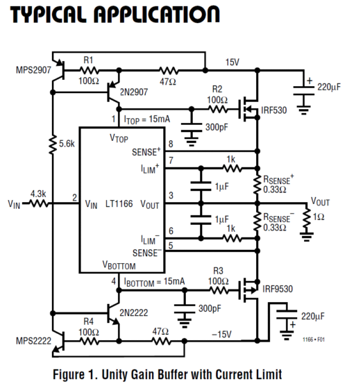
LT1166 I-out Amplifier
Well, with a little reconfiguring, we can create a current-output amplifier using this device at its core. First, let's look at the following design example from the same datasheet.
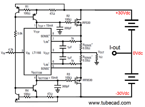
Note the 1-ohm load and the +/-15Vdc power supply rails. (This unity-gain power buffer would be great for driving 1-ohm ribbon speakers.) We start by increasing the rail voltages to +/-30Vdc, so that we can get more power into 8-ohm loads. This bipolar power supply must be floating, i.e. each channel must get its own +/-30V power supply that is NOT attached to ground at its midpoint, as the power MOSFETs will pull this floating power supply up and down to create the desired current flow through the loudspeaker. Second, note that the supporting transistors are no longer labeled. Why not? The transistors specified in the LT1166 datasheet are not high enough in voltage rating to be used with the 60V differential, so 100V devices would be a safer choice.
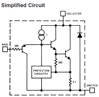
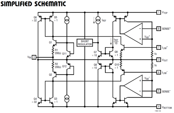
I know this circuit looks a bit too complicated, but it's not really. One problem is the non-conventional way in which the two constant-current sources were drawn. Okay, how many didn't see any constant-current sources in the schematic? (Maybe I should have completely redrawn the schematic.) Okay, now that you know that they are constant-current sources, how many now think the circuit doesn't look that complicated? Of course, if we look into the LT1166, the complexity skyrockets, as the following simplified schematic make clear.
In summery, the great advantage of using the LT1166 is that does a lot of essential housekeeping for us and it allows us to use the easily available and cheap IRF MOSFETs (IRF530 & IRF9530). Since this current-output amplifier offers a voltage-to-current conversion ratio of about 1V —> 1A, it would take about 3Vpk to drive it to full output with an 8-ohm load, so an additional frontend gain stage is probably not needed. On the other hand, if a tube gain stage were added, such as my Aikido design, then a feedback loop could be added, so the tubes controlled the MOSFETs' current swings. Although this voltage-to-current converter inverts the signal at its output, the feedback must attach to the common 1-ohm resistor and be returned to the input tube's grid, assuming that the tube gain stage inverted the input signal.
Next Time
//JRB |
|
I know that some readers wish to avoid Patreon, so here is a PayPal button instead. Thanks.
John Broskie
E-mail from GlassWare customers:
And
High-quality, double-sided, extra thick, 2-oz traces, plated-through holes, dual sets of resistor pads and pads for two coupling capacitors. Stereo and mono, octal and 9-pin printed circuit boards available.  Aikido PCBs for as little as $20.40 http://glass-ware.stores.yahoo.net/ Only $12.95 TCJ My-Stock DB
Version 2 Improvements *User definable Download or CD ROM www.glass-ware.com |
||||||||||||||||||||||||||||||||||||||||||


| www.tubecad.com Copyright © 1999-2011 GlassWare All Rights Reserved |