| John Broskie's Guide to Tube Circuit Analysis & Design |
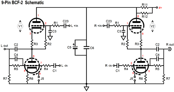
| Post 229 09 May 2012 BCF-2 PCB
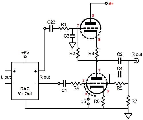
In addition, the BCF-2 holds four extra capacitors compared to the old BCF PCB. These capacitors can be used to implement a first-order, low-pass filter, which is useful for filtering a DAC's high-frequency noise.
BCF-2 Low-Pass Filter Frequency = 159155/C3/R1 or 159155/C4/R5 where C3 or C4 are in µF. For most DACs, a -3dB frequency between 80kHz to 160kHz works well. To keep the resistor noise to a minimum, use 10k resistors for R1, R2, R4, R5. With 10k resistors, 100pF for capacitors C3 and C4 will impose a cutoff frequency of about 160kHz. Since resistor R5 is effectively in parallel with resistor R7, the output coupling capacitor, C2, should be at least 1µF in value (16Hz low-frequency cutoff), with 3µF to 10µF providing deeper bass with less phase shift.
BCF-2 and DACs
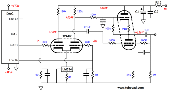
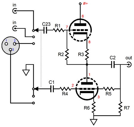
The 60-ohm I-to-V resistors will convert the DAC's 1mA of current swing into 60mV of signal, which the 12AX7-based input stage will amplifier up to over 3V. The BCF output stage within the Unbalancer will convert the balanced signal into an unbalanced output signal. On other hand, most voltage-out DACs put out plenty of signal, which makes the BCF-2 a better choice with voltage-out DACs. If the DAC puts out +/-1Vpk of signal, then the BCF-2’s output will be close to 1Vpk. The BCF’s intrinsically good CMRR will effectively ignore common-mode signals, such a power-supply noise; and capacitors C3 & C4 allow the BCF-2 to impose a first-order low-pass filter on the input signal, furthering the BCF-2’s suitability as tube buffer circuit for use with voltage-out DACs. Input coupling capacitor C1 can often be left off the board, as most balanced outputs already hold output coupling capacitors (capacitor C23 must be used at all times). With a voltage-out DAC, capacitor C1 must be used, as most voltage-out DAC ICs present, at their voltage outputs, a substantial DC offset, usually about 2.5Vdc. Of course, if you are not getting the DAC's output directly off the DAC chip but from the back of a commercial stand-alone DAC at its XLR jacks, then the signal is already capacitor coupled internally, so C1 can be left off. In other words, we can use the BCF-2 with the balanced output offered by the XLR jacks on the back of most standalone DACs and some high-end CD players. Since these audio units often already hold unbalanced RCA output jacks, why bother converting the balanced output signal into unbalanced? Two reasons, two very good reasons. First, the BCF-2 will intercept the DAC's output signal before it goes through an additional OpAmp (and possibly some extra electrolytic capacitors). This makes a surprisingly big difference in the sound quality, far beyond what I expected. Second, the BCF-2 uses tubes, whose sonic attributes are known by all, even by the maker's of solid-state gear, as we witness by all the ads that proclaim that their solid-state amplifier sounds tube-like. When is the last time you saw an ad for a piece of tube gear that proudly boasted that it sounded like a solid-state amplifier?
BCF-2 Tube Types & B+ Voltages
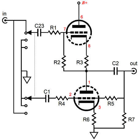
The following circuit allows the BCF-2 to select the phase of its output signal with an unbalanced input signal.
The BCF-2 PCB and kit are available now at the GlassWare Yahoo store.
Aikido Single-Ended Output Stage
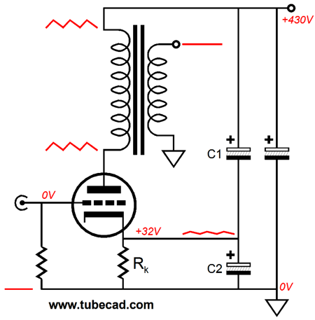
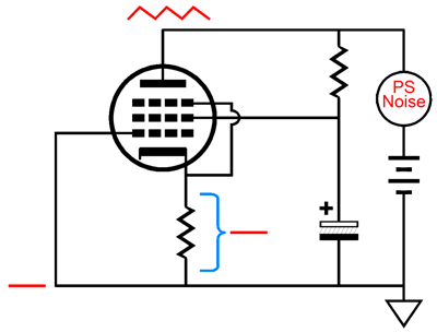
In this circuit, C1 injects a small amount of the power-supply noise into the output stage to null the noise from its output. The right amount results in the plate experiencing the same amount of power-supply noise as the output transformer's connection to the B+, which means the transformer never sees any noise voltage developed across its primary; hence, no noise at the output. Because the output tube amplifies the cathode signal, the amount of noise needed at the cathode to match the power supply connection is equal to Ratio = 1/(mu + 1), where mu is the amplification factor the triode used. For example, if the mu equals 10, then the amount of noise needed at the cathode would be 1/11th of the power supply noise. When capacitors are used to divide an AC voltage signal, the division is the inverse of resistors. Here the smaller valued capacitor develops the greatest signal voltage across its leads. The ratio between bottom and top capacitance is C2 = mu x C1 For example, a mu of 8 and 470µF for C2 requires that capacitor C1 equal 59µF. Most electrolytic capacitors hold more capacitance than labeled, so be sure to measure before soldering. Although to be honest, a triode's mu is not as fixed as many believe and getting close is usually good enough. No, my new Aikido technique is a bit different—okay, wildly different. (The technical term for that last sentence is epanorthosis, the addition by correction. Where most see electronic parts, I see topology; where most see words, I see figures of speech.) But before looking into the new design, let's review a plain, vanilla, fixed-bias, single-ended output stage.
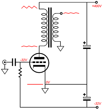
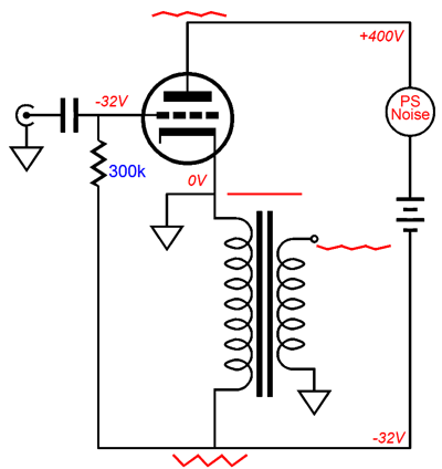
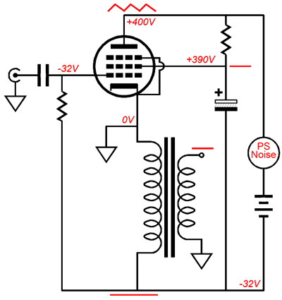
As I wrote back in that 1999 article on improving an SE amplifier's PSRR, "Here's the rub: the low rp, which proved wonderfully advantageous in lowering the amplifier's output impedance, now proves to be a hindrance to low noise operation." Indeed. A triode's low rp defines the bottom resistor in a two-resistance voltage divider, with the reflected load impedance presented by the output transformer's primary acting like the top resistor. The lower the rp, the more B+ ripple appears as signal to the output transformer's primary. If we invert the circuit, so the output transformer attaches to the cathode and the power supply is allowed to float, not being directly attached to ground, the same amount of power-supply noise leaks out to the speaker.
A giant step sideways, it seems. Nonetheless, this inverted SE amplifier offers some seductive advantages. For example, the output transformer's primary is grounded at one end, not at the B+ connection, making the output transformer a bit safer, should a short to the transformer housing occur. In addition, the output transformer's primary is doing double duty, as it also biases up the output tube, much in the same was as a cathode resistor would, because of its relatively high DCR. (And let's not forget about global warming, as using the output transformer's primary as a cathode bias resistor will reduce the heat dissipated by the amplifier by about 3% compared to a cathode-resistor-based amplifier, making the amplifier so much more green friendly.) In fact, in previous posts, I have argued in favor of such a topological inversion, as it would allow a feedback loop to be ground referenced. In other words, the negative feedback would not worsen the PSRR figure the way it does when attached to the the tube's plate. (In a conventional single-ended amplifier, the output transformer terminates into the B+ connection, not ground. If eliminate all power-supply noise at the output tube's plate, the noise at the secondary goes up, not down. Thus, terminating a negative-feedback loop at the plate will lower the output impedance, but it will worsen the PSRR. Of course, I have some clever workarounds, but that's for another blog post.)
With a single tube, the feedback approach shown above makes little sense, as a huge input signal would be needed. But with a two- or thee-stage, inverted, single-ended amplifier with a floating power supply, attaching the negative feedback loop to the bottom of the output transformer's primary is the way to go. Still, we have the problem of the floating power supply, which makes building a stereo amplifier more difficult, as each channel will need its own floating power supply (and possibly a third power supply for the input and driver stages).
New Aikido SE OPS
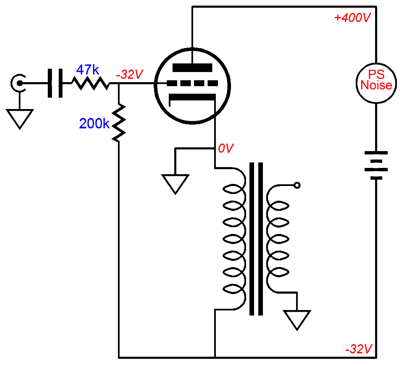
Nothing exceptional here, as the pentode's "grounded" grid and screen effectively shield the cathode from power-supply noise at the plate. This is something old timers knew quite well: that a pentode-based power amplifier didn't need a regulated B+, if the screens received a regulated voltage (or at least a well filtered DC voltage). The next step is to create a triode-connected pentode output stage that exploits the above topology.
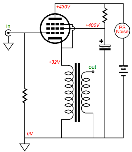
Wait a minute, that pentode is not triode-connected. Sure it is. If the plate moves up 10V, the screen moves up 10V; if the plate falls by 10V, the screen falls by 10V. Inversion is not easy to grasp, I will admit; nor is a floating power supply. The key element here is that the floating power supply does not directly attach to the signal ground. In addition, note how the output tube's plate is tightly coupled to the output transformer's primary through the floating power supply, in AC terms. If the plate moves up 10V, the bottom lead of transformer's primary moves up 10V; if the plate falls by 10V, the bottom of the primary falls by 10V. Next, we look at the noise relationships within this output stage.
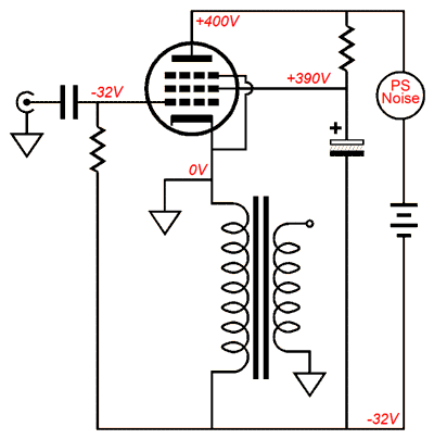
To be honest, the above schematic exaggerates the improvement in the PSRR, as a perfect noise null does not occur; instead, as revealed by SPICE simulations, a PSRR figure of -28dB obtains, which compared to the -3dB of the comparable single-ended output stage with the same load impedance and tube, is quite excellent. Now, let's look at some actual part values for a real-life example.
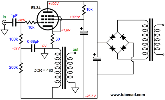
Here we see the EL34's supporting circuitry and the floating power supply fleshed out a bit. Where to start? The 10k screen resistor seems to be in parallel with the load impedance; it isn't, as it sees a fixed DC voltage and all the AC power-supply noise. The 0.68µF capacitor connected to ground is there to filter away the output transformer's huge 250V voltage swings from the grid circuit. Remember the output transformer's primary will swing both hugely negatively and positively, but the average should equal the idle state's nominal -32Vdc. The 30-ohm cathode resistor is there to add some resistance to the output transformer's primary's DCR and to allow easy measurement; besides, it linearizes the output tube a tad. (The real reason it's there is that I envision three EL34s working in parallel, with a UBT-1 output transformer with a DCR of 160 ohms; and I want to prevent current hogging by any of the output tubes.) Before moving on, notice how the above circuit looks very much like a cathode-follower circuit, although it is a grounded-cathode amplifier. (Note where the ground attaches.) What would it look like if it were a cathode-follower power amplifier stage?
This power buffer will require a truly huge input signal, say +/-260Vpk, which only ES headphone amplifiers can provide. Still, it would offer some fine features, such as low-distortion, low output impedance, and wide bandwidth.
What is the point of a stand-alone output stage without an input and driver stage? Other than simplicity and great sound, nothing. I have built EL34-based single-ended power amplifiers that held neither an input nor a driver stage. Why? The tube is so efficient that it only needs about +/-34Vpk to drive it to full output, which I was able to give it with my tube line stage amplifier. In other words, why add extra gain stages and fistfuls of parts to the signal path, if you do not have to? Okay, what if you are running a passive line stage with no gain? In that case, an input and driver stage would come in handy. Here is one possible configuration.
Click on schematic to see close up (Only one of the three output tubes is shown.) I have added an Aikido input stage, which can easily drive the amplifier to full output. This gain stage gets its power from the floating power supply, which means that the 6mA that the frontend draws must also flow through the output transformer secondary. If a beefier set of Aikido tubes are used, say a 6N1P and 6H30, then a separate power supply for the Aikido stage will be needed, as too much current would flow through the output transformer. But it might be better separate these gain stages from the power amplifier and place them in their own box with their own regulated heater and B+ power supplies. Of course, these extras could be placed in the power amplifier's chassis, but they so seldom are. Moreover, a line stage requires a lot of running signal wires from the input jacks to the selector switch to the volume control—all of which would be subject to interference from the high currents within a power amplifier. This is why we have separate line stage amplifiers. Some like to place their amplifiers right next to the speaker being driven, which makes for very short speaker cables and very long interconnects. Well, I favor this approach, as a speaker cable must deliver both current and voltage, whereas an interconnect delivers primarily voltage. And I would argue that the bigger the voltage swings that we can force through the interconnects the better. Why? I suspect that something like transformer-core hysteresis is going on within the interconnect; and using a naked output stage forces us to swing big volts into the interconnects, which reduces this effect by swamping it out. True, a naked cathode-follower power buffer shown above would be too naked; just imagine the danger of touching the male RCA plug prong that carried +/-260Vpk. I expect that soon some enterprising high-end-audio company will begin selling interconnects that hold no wire, consisting of only two small enclosures (each with a single RCA plug and nothing else), as they will rely on a WiFi signal to connect the two units (battery powered no doubt). But even such a device will not be needed when most loudspeakers hold DACs and digital crossovers and internal class-D amplifiers and—most importantly—their own WiFi receivers.
Indeed, I can imagine, in the future, an audiophile telling his children that when he was a lad, stereo systems required a tangle of wires, wires everywhere, some thicker than a garden hose and costing twenty times more than their antigravity hovering boards (which float three inches above the ground). "Icky," his children will respond and he will nod his head in agreement. Very icky indeed.
Warning!
Next Time
//JRB |
I know that some readers wish to avoid Patreon, so here is a PayPal button instead. Thanks.
John Broskie
E-mail from GlassWare Customers
High-quality, double-sided, extra thick, 2-oz traces, plated-through holes, dual sets of resistor pads and pads for two coupling capacitors. Stereo and mono, octal and 9-pin printed circuit boards available.  Aikido PCBs for as little as $24 http://glass-ware.stores.yahoo.net/
Support the Tube CAD Journal & get an extremely powerful push-pull tube-amplifier simulator for TCJ Push-Pull Calculator
TCJ PPC Version 2 Improvements Rebuilt simulation engine *User definable
Download or CD ROM For more information, please visit our Web site : To purchase, please visit our Yahoo Store: |
|||


| www.tubecad.com Copyright © 1999-2012 GlassWare All Rights Reserved |