| John Broskie's Guide to Tube Circuit Analysis & Design |
| Post 241 30 August 2012
More Interconnects
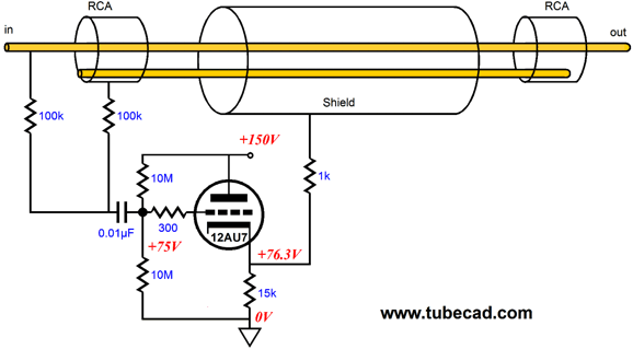
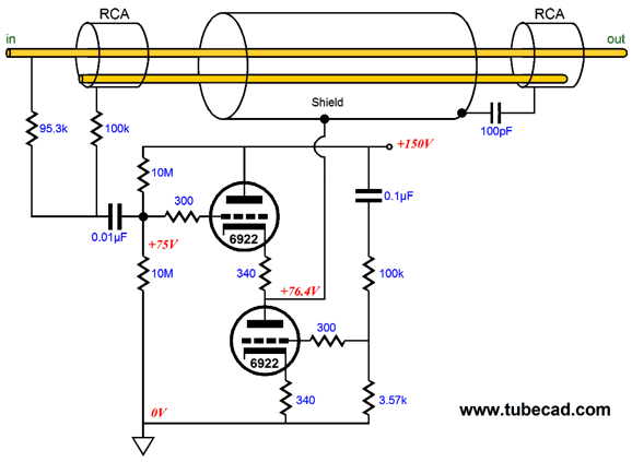
Two goals are achieved with this circuit: a pseudo balance is forced on the unbalanced interconnect and the high-voltage present on the shield polarizes the interconnect. The 12AU7 was selected because its heater can be placed across an external 12V power supply. The assumption here is that one tube would be used for both channels and that a 12V-to-180V DC-to-DC converter would be used for the B+ voltage. On the other hand, if you are willing to use two tubes, then our choice of tubes expands. For example, the following Broskie cable uses one 6922/6DJ8/E88CC tube per channel, the two 6V heaters placed in series. Instead of a simple cathode follower, the Aikido cathode follower drives the screen, which bestows its wonderful PSRR upon the design.
Note 95.3k resistor that attaches to hot conductor; this smaller value will deliver more of the input signal to the ACF, compensating for the gain loss from the follower. The 100pF capacitor is a protection device that AC grounds the output end of the shield at ultra-high frequencies; an antenna-prevention device, in other words. (A second capacitor could be added, which would attach the shield to the hot conductor at the output end of the cable.) Who would have thought a simple audio interconnect could be made so complex. Well, it need not be, as we can forgo the warm glow of the tubes, yet retain the pseudo balance and polarized cable aspects of the design.
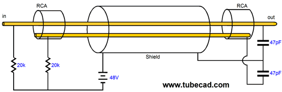
In this design, four 12V batteries are used to create a 48V voltage source. A23 batteries also put 12V. If you are lucky, you might find Energizer NO. 415, which puts out 45V! Unfortunately, I doubt that they are still being made.
No matter which battery(s) is used, it will last a long time (the shelf-life of the battery), as it doesn't actually power anything. Of course, an actual power supply could be used instead of the battery, such as the following.
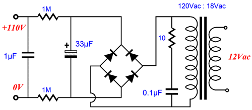
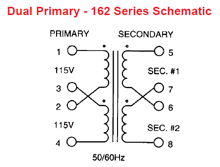
The 10-ohm resistor and 0.1µF capacitor are there to capture RFI and turn it into heat. The two 1M resistors define an RC filter with the 1µF capacitor. The transformer is a 12V to 18V type that is driven backwards: the secondary is attached to a 12Vac wallwart. Hammond Manufacturing offers the model 162D36, which is a tiny, 1.1VA, PCB-mount transformer:
Remember that each channel must get its own rectifier bridge and RC filters. If more DC polarizing voltage is needed, then a 12Vac transformer could be used; if less, then a 24Vac or 36Vac transformer. Or if having to buy $200 NOS tubes for your interconnect seems too daunting, then how about $1 worth of transistors instead?
The two high-voltage transistors take the place of one triode, although a single MJE340 NPN transistor would suffice. The major advantage this transistor-based Broskie cable holds over the tube versions is that it can be left on 24 hours. Two of these circuits with a 170Vdc raw DC power supply would only dissipate 1W. And none of the transistors require a heatsink.
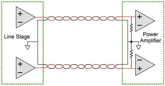
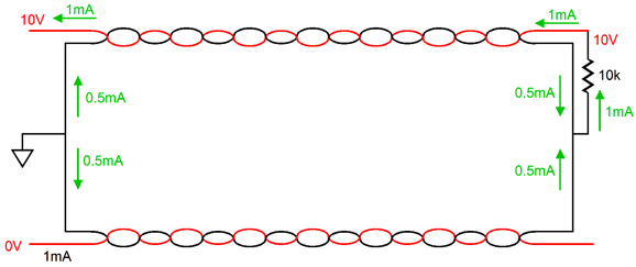
The Interconnect Problem Unfortunately, the RCA plug and jack escaped from this limited use and we have been stuck with the inherent problems in the design since. For example, the jack only weakly holds the plug's hot pin, the hot pin makes contact before the ground, the plug weakly grips the jack, and the RCA-terminated interconnect now externally connects many pieces of audio gear together, each holding its own power supply, each with its own signal ground. A very bad design. Here is a typical setup, with a linestage amplifier driving a stereo power amplifier via an RCA-terminated, stereo interconnect.
Note the two grounds, one in the line stage and one in the power applier. Note how the two ground conductors in the RCA-terminated interconnect are in parallel with each other. Note how an audio signal in one channel can return down both ground conductors. For example, if 10V is present on one channel, the current flow through the power amplifier's 10k input resistor (or volume potentiometer) will equal 1mA, half of which will travel through both ground leads.
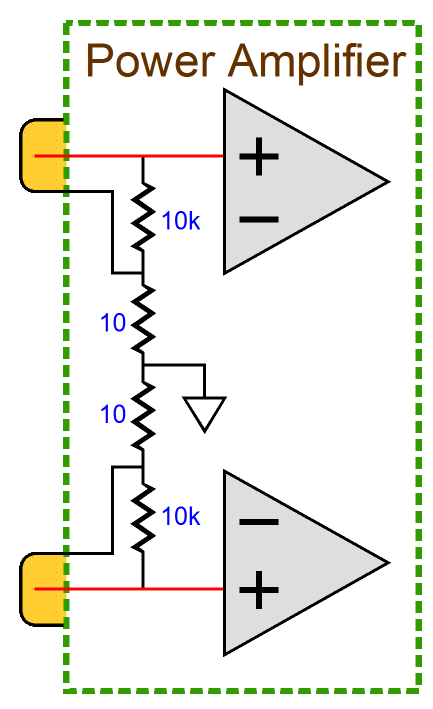
So much for fancy conductor winding, as the channel with no signal still sees the current flow from the driven channel. How do we keep all the current flow in only the driven channel? Well, we could use monobloc power amplifiers. Ideally, with two independent power amplifiers, the only current path back to the line stage would be through the driven interconnect. And this sometimes happens; but if each mono power amplifier connects its signal ground to the house ground via the third prong on the power cord, we are doomed, as the once independent grounds are now connected through the wall wiring. One failed solution that I tried was using insulating washers on the RCA jacks on the stereo power amplifier and placing 10-ohm resistors between the jack's ground lungs and the amplifier's signal ground. My thinking was that the signal in one channel would much prefer to travel down its 0.00001-ohm ground conductor, rather than travel through the 20 ohms of resistance to the other channel's ground conductor lead back to the line stage.
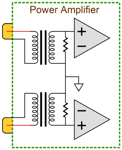
Well, that was the idea. In actual use, I ran into one problem: Huuummmm! An amazing amount of hum. The best solution would be to use two isolation transformers in the power amplifier.
The transformers relay the signal, but make no direct connection to the interconnect ground wires. This would force the signal currents to remain in each channel's interconnect and it would side step many other problems such as the house-ground ordeal. Of course, the problem with transformers is that high-quality transformers are both expensive and rare. I decided to try something simple, since I couldn't beat it, I might as well join it.
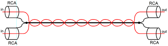
I quite enjoy braiding wires into cables, so I took three teflon-coated, multi-strand, copper wires and made a two channel interconnect. (I actually used four wires, but the ground wires were solder together at each end and at the center.) How did it sound? I liked it at the time, but then every mother's child is beautiful. Of course, this design assumed that the two sets of RCA jacks would be close together and it could not be used with two monobloc power amplifiers. (This cable was intended to connect a CD player to a line stage.) I then decided to try something altogether different. I really liked the idea of using 10-ohm resistors to "float" the ground connections. But how could I eliminate the hum problem? Before showing my solution, let's look at a typical solid-state power amplifier layout.
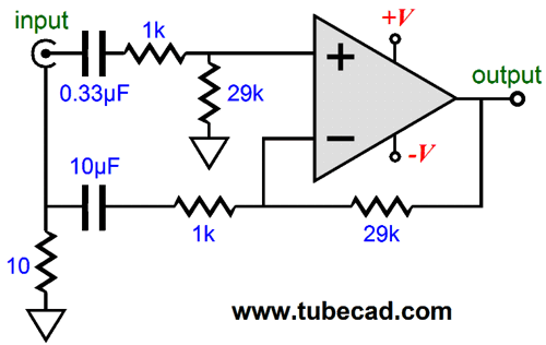
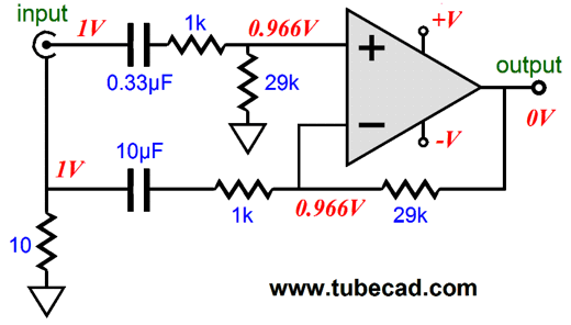
The feedback resistors set an AC gain of 30. The 100µF capacitor effectively increases the DC negative feedback, so the DC offset is low at the output. Well, nothing special here. If we want to convert this amplifier into a differential amplifier, we will have to add a few more parts. Wait a minute, why would we want a differential amplifier? The great advantage offered by the differential amplifier is its ability to reject common-mode signal, such as a hum signal present on both the hot and ground conductors of an unbalanced interconnect.
I replaced the electrolytic capacitor with a high-quality film capacitor and I added an input coupling capacitor. Why? I didn't any input DC offset to be passed on to the output. The gain has dropped down to 29 from 30, but the CMRR has increased dramatically. For example, if 1Vpk of 60Hz signal appeared on both the positive and ground connections to the RCA jack, then the amplifier's non-inverting input would see 29/3oth of the signal and, thus, its inverting input must also see 29/30th of the same 1Vpk of signal at the top of the 10-ohm resistor. Well, the only this condition can be met is if the output remains at 0V. In other words, the amplifier refused to pass the common-mode signal on to its output.
(If a gain of exactly 30 is truly needed, then the 29k resistors can be replaced by 30k resistors.) An additional advantage afforded by this topology is that the amplifier's DC offset will be prove quite low, as its differential input stage will see identical DC resistances to ground and to the output, i.e. 29k. But how did it sound? Here is the problem: it sounded much better to my ears, but was that due to the film capacitor replacing the electrolytic capacitor or due to the CMRR trick or due to my fooling myself? Who knows for sure? I certainly don't. Never change more than one variable at a time, if you want to perform a good experiment. Yeah sure, but since I got the soldering iron hot, I may as well... Don't. Make one change, listen, make another change, listen... Speaking of differential input stages, it would be fun to apply the above technique with the Unbalancer circuit and unbalanced inputs.
The non-inverting input would receive the hot signal and the inverting input would attach to the top of the 10-ohm resistor.
This configuration uses a balanced input to work with a seemingly unbalanced input signal source. And since the Unbalancer puts out an unbalanced signal, no one would know what was actually going on, except you and me.
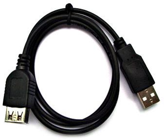
CAT-5 & USB Cable
My house is filed with USB cables and I own a few extra-long cables are at least 10 feet long. I could easily hack together some interconnects out of a USB cable. Who knows, it might even sound good, particularly if the shield was driven with 50% of the signal by a tube buffer stage.
Old and Warm and Tinted Wire Another audiophile told me that warm wire sounded better than cold wire. He said that this was easily testable by taking identical interconnects or speaker cables and placing one in a zip-lock bag in the freezer and placing its brother in the hot Colorado sun for an hour; then perform a shootout. To be honest, I never performed his test. Why not? I was afraid that if he was right, I would be constantly applying a hot iron to my interconnects and speaker cables. Still, it would be a fun experiment to perform and I do know that cold phono cartridges don't sound as good as warm ones. Imagine a shielded interconnect, whose shield purposely conducted a steady DC current from one channel's shield to the other channel's shield. Why? To heat the interconnect, of course.
Here is quick aside. I once talked to a famous designer of solid-state, high-end audio gear. He told me that the reason interconnects sounded different was because they saw too little current flow. He shorted the RCA jacks on his power amplifier with 470-ohm resistors, right on the back of the RCA jack. His line stage held a robust output stage and could easily drive this low-impedance load. He told me that now all interconnects sounded the same: very good indeed. I liked his idea that the higher current flow burned through the interconnect's quirkiness, but as a tube-loving man, I didn't see how I could do the same. For example, a 470-ohm load requires a 20µF coupling capacitor and a fairly buffed output stage. Since this is the odds-n-ends section, I will mention that I have read that Japanese audiophiles hold that the sheathing on a interconnect wire must be either clear or gray, but never red or black or blue... Why not? They argue that the coloring chemicals used alter the electrical characteristics of the interconnect. I know, I don't see how it could either; but I thought that I should mention it. This brings up the topic of dielectrics, nonconductors of electricity, especially those substances with electrical conductivity less than a millionth of a siemens and which exhibit a high degree of polarizability. If you read the white-papers from cable manufacturers, you often walk away with the perception that wire is the least important part of the interconnect: its the dielectric, stupid.
Thus, we see ads for interconnects that use teflon or polyvinyl-chloride or polypropylene or polyethylene or air or vacuum or rice paper or silk or silly putty... Okay, I made that last one up; but why not? It's at the center of many of the finest golf balls. Or how about chewing gum or spider web? The Black Widow interconnect! As for me, I like Teflon-coated wire, but I hate working with it. Stranded or solid-core, copper or silver or silver-plated-copper—in general, these are our choices in wire. I like silver-plated-copper. One fellow told me that he was using carbon-filled spark-plug wires, which purposely present a high resistance. Interesting. Maybe you haven't noticed, but spark-plug-cable technology is quite advanced these days. It has to be. Copper-cored spark-plug cables make big sparks, but also make lots of RFI, so much so that the car's radio and computers are disturbed. Thus, the move has been to high-resistance spark-plug cables. Beware that some of the best spark-plug cables hold ferrite-based cores, which might sound dreadful. Other spark-plug cables use a ferrite outer shield, which might be cool. But don't imagine that this might be the cheap way to make high-end audio cables, as spark-plug cables can cost a fortune. One cable designer told me that the critical aspect of good interconnect was mechanical tightness: the stiffer the better. He argued that the interconnect's wire strands acted like little electrostatic speakers, in that they moved back and forth with the music, turning subtle detail into physical motion and heat. Well, I have experienced singing capacitors, wherein a capacitor in a high-voltage circuit becomes a tiny electrostatic speaker. Still, I have a hard time believing that cables that weigh millions of times more than electrostatic speaker diaphragms and see one thousandth the voltage swing and none of the bias voltage could be made to move above the thermal agitation of the cable's molecules. Then we have the topic of breaking in interconnect. Many have the same experience: they buy a fancy and expensive interconnect and it doesn't sound much better than what they were using before. They conclude that the interconnect has yet to break in; and, sure enough, two weeks, maybe two months later, the interconnect is broken in and sounds fabulous. I don't deny that this experience has happened, as I am sure that it happens all the time. No, my take is that the listener's ears have broken in, not the interconnect. Here is an analogy, I usually find that I don't understand the French or Spanish spoken in a foreign movie, at first; but by the end of the movie, I do. Well, therefore, the movie film must require some break-in time. What else could be the cause of my improved recognition? It is a simple test: take two sets of identical interconnect and plug one set into the outs of an FM tuner and terminate the other end with a 47K resistor; then let the tuner play for a month or two. Now, hold a shootout with the cable that did nothing. Or am I not getting it? Does interconnect break in only occur if someone listens to it? Wow, very phenomenologically heavy this notion. Okay, what if the interconnect in use is located in a 24-hour store and it connects the Muzak stream to the PA system? Still, I used to use an interconnect-breaking-in device. I took a small plastic box and drilled four holes for RCA jacks and a hole for power cord and one for wall socket. I then plugged in the interconnect and plugged the power cord into the wall socket, so I could power a 100W table lamp. The 117Vac ran through both the hot and ground conductors. I let it run for a few days and I assumed 165Vpk sinewaves would break in the interconnect. The UL would not approve, I know.
Interconnects: The Punch Line We were shopping in a big department store last night. My nine-year-old son was troubled by the women's intimate wear section of the store. Why, he wanted to know, why all the frill, embellishment, extra effort, folderol, frippery, frou-frou, gewgaw, luxury, ornamentation, superfluity, trimming for clothing that no one ever sees? Like a stern Soviet bra commissar, he was irked by the costly and unnecessary luxury, the extravagance, indulgence, and nonessential aspect of it all.
I explained that it was possible that a woman would be in an accident and she wanted to make sure that she looked good in the hospital, as they cut away her outer clothing. Amazingly, he was satisfied with my ludicrous answer. A better answer would be: it is her money; if it makes her happy, it makes her happy and it's no one else's business. Moreover, "Only as an aesthetic phenomenon is the world justified," as Nietzsche so wisely pointed out. Well, the same can be said about bras, panties, interconnects and, while we are at it, the whole of high-end audio. If you got the money to burn, burn it as you please. If you like tinkering, then tinker. As Ralph Waldo Emerson put it so nicely, "All life is an experiment. The more experiments you make the better." For less than $20 you can make a fine interconnect; for only $2,000 you can buy an interconnect that will impress your friends. The choice is yours and your's alone. I will end with a story about a friend of mine who robustly renounces all expensive, fancy cables, be they interconnects or speaker or power cables. He owns expensive, high-end audio gear and he uses the cables provided or those left over from previous audio purchases. Many audiophiles recoil and quiver in repugnance by his cable nonchalance, his supreme indifference. I have to admire such bold self-composure, self-possession, such a robust repudiation of audio custom. As he likes to say, "It's just wire, God damn it."
Yet I am reminded of the story that Robert M. Adams tells in his wonderful, but out-of-print book, Bad Mouth: Fugitive Papers on the Dark Side*,
If your mother didn't warn you against being pretentious in blatant humility, she should have.
Next Time * I love this book, yet I would never recommend to a general audience. Why not? It is too high-end, in terms of both writing and thought—even though its topic is the despicable. It's the same with many of the writers I most enjoy: I know few would also enjoy them. For example, I get dizzy from reading William Gass, finding his verbal high-wire acts breathtaking, but I am sure that most of his readers just grow weary and confused—and they are not altogether wrong for doing so. Here is what a one-star reviewer at Amazon.com said about Gass's book, On Being Blue:
Another reviewer, a five-star leaver, wrote with the subject line of "Keep at it,"
To my list of writers that I solitarily enjoy, I must add James Gould Cozzens. I love his fiction, yet I would never recommend his novels, although I would place him in the top five American novelists of the last century.
//JRB |
I know that some readers wish to avoid Patreon, so here is a PayPal button instead. Thanks.
John Broskie
E-mail from GlassWare Customers
High-quality, double-sided, extra thick, 2-oz traces, plated-through holes, dual sets of resistor pads and pads for two coupling capacitors. Stereo and mono, octal and 9-pin printed circuit boards available.  Aikido PCBs for as little as $24 http://glass-ware.stores.yahoo.net/
Support the Tube CAD Journal & get an extremely powerful push-pull tube-amplifier simulator for TCJ Push-Pull Calculator
TCJ PPC Version 2 Improvements Rebuilt simulation engine *User definable
Download or CD ROM For more information, please visit our Web site : To purchase, please visit our Yahoo Store: |
|||


| www.tubecad.com Copyright © 1999-2012 GlassWare All Rights Reserved |