| John Broskie's Guide to Tube Circuit Analysis & Design |
Post 243 18 September 2012
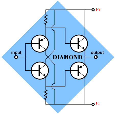
Interconnect & Speaker Cable: Long or Short? If I had to choose, I would prefer long interconnects and short speaker cables. But what would make me happier still would be long interconnects and a very-hot line stage amplifier, which could put out 40Vpk of clean signal, more than enough to drive a unity-gain power buffer situated behind or, perhaps, located within the loudspeaker. Why? A variety of reasons, such as the pursuit of novelty and simplicity. Tubes work well with high voltages and can easily swing big voltages, so using a tube-based line stage makes a lot of sense, if you desire huge output swings. For example, an Aikido line stage based on a 12AX7 input tube will provide a gain of about 50 (or +34dB), which is plenty. (Of course, a flea-power power buffer, say one that put out only 4W, would need only 8Vk of input signal; 50Vpk into an 8-ohm load equals 156W, real watts, not peak-power watts.) In addition, power amplifiers, be they tube-based or solid-state-based, have enough work to do by having to deliver high current into a speaker; adding voltage amplification to its lists of tasks just complicates its design and construction. And why duplicate functions? Why cascade two voltage gain stages when one will do? Freed of the job of voltage amplification, building a solid-state power buffer is easier than building the equivalent solid-state power voltage amplifier, as the unity-gain power buffer can consists of only an emitter-follower or source-follower output stage, only one stage, not the typical three: voltage-amplification stage (VAS), driver stage, and output stage.
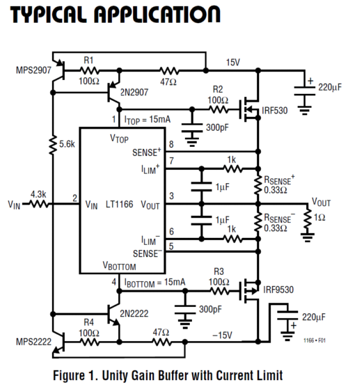
Or, if you fancy MOSFETs over bipolar transistors, then the LT1166 might be the answer.
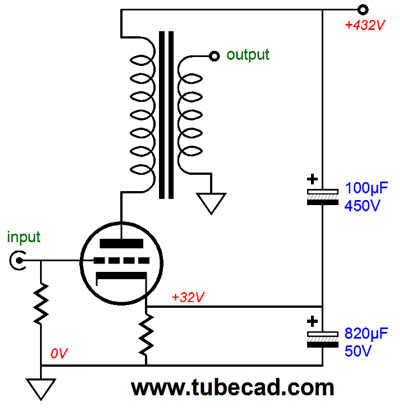
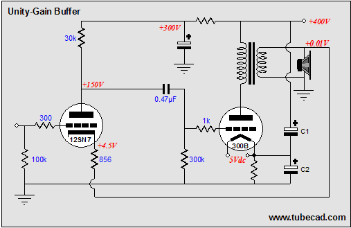
Note the 1-ohm load; with an 8-ohm load, much higher power-supply rails can be used. See Blog 211 for more details. Even a single stage tube-based unity-gain, power buffer can be built, but not in a cathode-follower topology, alas. indeed, with tube power buffers, things get a bit more complicated. For example, the following tube power buffer uses a grounded-cathode amplifier. Thus, although the same amount of output voltage develops as input voltage enters, say 10Vpk in and 10Vpk out, it does so because the output transformer steps down the plate voltage swings. For example, 10Vpk goes in and the plate swings 50Vpk, but the output transformer’s 5:1 winding ratio reduces the 50Vpk to 10Vpk at the secondary. A closer approximation to a true tube-based power buffer would require at least one more stage. A tube-based, negative-feedback-based, unity-gain power buffer might look like the following.
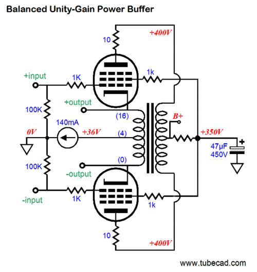
This circuit appeared in Blog 68, whose topic was tube power buffers. But tube and solid-state unity-gain, power buffers have been covered here countless times (well, at least countless times as far as I am willing to count). For example, here is an interesting balanced power buffer from Blog 190.
Note the pentode topology and the constant-current source, which auto-biases the output tubes (matched tubes). Normally, a pentode output stage presents a very high output impedance, which requires that the input stage apply a big dollop of negative feedback to reduce Zo. But in this tube power buffer, the feedback is applied directly at the output tube's cathodes. Also note that the center-tapped secondary sits at the bias voltage, +36Vdc, not 0Vdc. What appeals to me most is the simplicity of these designs. “Simplicity is the ultimate sophistication,” so said Leonardo da Vinci. Less can be more, although it can just as easily be a bore. Well, I have been thinking about a stereo system that held a high-gain, tube-based, line-stage amplifier and long interconnects and monobloc unity-gain power buffers, with short lengths of speaker cable. Thus, this type of circuit interested me. And as I can never leave any circuit unmodified, I have come up with a clever modification of the single-ended inverted amplifier. As Leonardo also put it so well, “Art is never finished, only abandoned.”
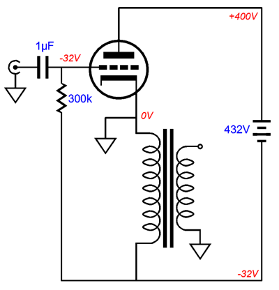
Auto-Bias Single-Ended Output Stages
It may not look right, offending the eye and long-held custom, but the amplifier functions identically to its more conventional brother. It is still a grounded-cathode amplifier, not a cathode follower; it offers the same output impedance and voltage gain; and if we strip away the two-capacitor Aikido trick from the conventional single-ended output stage, the same PSRR obtains. What we have acquired from this inversion is a slightly more efficient use of the available B+ voltage, as the voltage that the output transformer’s primary will displace, due to its DCR, is no longer wasted, as it now serves to cathode bias the output tube. But this advantage is minor and the primary’s DCR is no better than a cathode resistor in establishing a precise idle current. Achieving a steady fixed idle current will require a constant-current source.
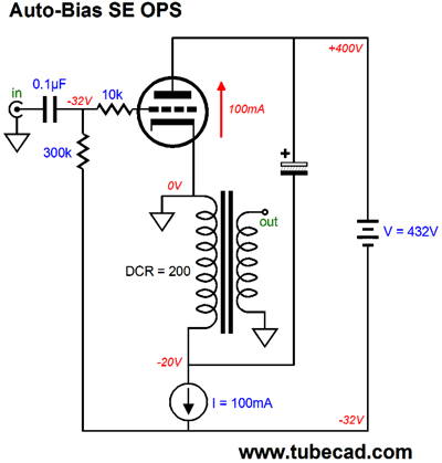
The constant-current source will automatically adjust the output tube’s grid-to-cathode voltage to maintain a fixed idle current. The large-valued electrolytic capacitor that shunts the output tube and output transformer will allow the output stage to amplify audio signals. The high-voltage battery is just a placeholder for a more complex floating power supply. In fact, this entire schematic is rather idealized, as a truly functional circuit will require more parts and more complexity. But before moving on, let’s examine how the constant-current source shields the output stage from power-supply noise.
In this example, as long as the power-supply noise does not exceed 12Vpk, the constant-current source will vary its voltage drop with the ripple, so the output stage sees a fixed voltage window to operate within. Okay, that’s great, no power-supply noise at idle, but what about amplifying music? How can the output tube amplify, if its plate and cathode see a fixed DC voltage? Actually, only the cathode sees a fixed voltage, as the plate is free to move up and down in voltage as prompted by the grid signal. For example, a positive input voltage will provoke an increase in the tube’s current conduction, which will pull down its plate voltage, just as it would in a conventional single-ended plate amplifier—the power supply is floating after all. As the plate pulls down 100V, the output transformer’s primary sees an additional 100V voltage drop. Conversely, as the tube conducts less, its plate voltage will increase causing the output transformer’s primary to see voltage reversal, as the electrolytic capacitor pulls it connection to the primary upward. Because the power supply is floating, each channel will require its own power supply. What does the constant-current source see with these big plate-voltage swings? Essentially, nothing much: just the 12V voltage drop and the power-supply ripple. Relative to ground, the constant-current source is swinging up and down with the big voltage swings; but differentially, the constant-current source sees the same low-voltage drop. Okay, ideally it sees the same 12V drop. But a speaker cable breaking contact or shorting can provoke a huge primary voltage that can overwhelm the constant-current source. The workaround is a 50 cent zener diode.
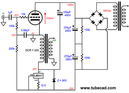
Now that it has been fleshed out, I admit that this schematic looks much more complicated. The battery has been replaced with an actual high-voltage power supply. Two 270µF capacitors are placed in series, which halves the capacitance, but doubles the voltage rating. The two 100k resistors shunting the power supply capacitors work to establish a true voltage division between power-supply capacitors. If the power transformer is center tapped, then the two voltage-divider resistors are not required, as the center tap will halve the voltages for us.
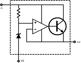
The LM317 is an adjustable, three-pin, voltage regulator that has been configured as a constant-current source. Internally, the LM317 holds a voltage reference, an OpAmp, and a power NPN transistor. The internal OpAmp constantly monitors the voltage at its “adjust” pin, comparing it to the voltage reference’s output.
If the adjust pin voltage falls below the reference voltage, the OpAmp increases the transistor’s current conduction; if the adjust pin voltage climbs above the reference voltage, the OpAmp decreases the transistor’s current until the adjust pin voltage falls enough to match the reference voltage. In other words, the LM317 strives to maintain a fixed voltage drop across 12.5-ohm resistor. Thus, if a constant voltage exists across the resistor, a constant current must flow though the resistor. The maximum voltage the LM317 can withstand is 37V; a high-voltage version is available, the LM317-HV, which can withstand 57V. The 30V zener protects the LM317 against inductive kickbacks that can produce huge voltage swings on the output transformer’s primary and against the 100µF capacitor's slow charge up at turn on. If the zener sees more than +30V, it begins conducting, halting the voltage increase to 30V; if the zener sees a negative voltage, it begins conducting like a normal rectifier, with a fixed voltage drop of about 0.7V. In other words, the zener sets an operational voltage window of +30V to -0.7V for the LM317 to work within. The 0.68µF capacitor is needed to prevent the power-supply noise and the huge signal voltage swings from dragging down the signal source. The 200k resistor and 0.68µF capacitor define a low-pass RC filter with transition frequency of about 1Hz. Thus, the DC voltage gets through as though the capacitor was not there, but AC signals above 1Hz are greatly attenuated. The effective input impedance is not 300k (100k + 200K) as we might guess, but 100k. The input coupling capacitor is needed to isolate the negative-bias voltage from the signal source. The 10k grid-stopper resistor is essential, as it prevents the output tube from oscillating at some super-sonic frequency. The 100µF/450V capacitor stores the voltage charge that the output tube and output transformer will work within; it can be (and should be) bypassed by a high-quality film or PIO capacitor. Since the output stage operates in single-ended, class-A, this capacitor has little work to do, as the output stage draws a fairly constant current on average. The output transformer’s primary is part of the biasing setup, as its DCR helps bias the output tube. With a 100mA of idle current flow, the 200-ohm DCR will drop 20Vdc, leaving it to the LM317 to drop the needed 12Vdc to establish the required -32Vdc for the tube’s grid relative to its cathode.
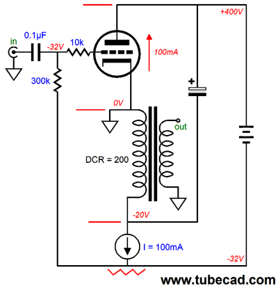
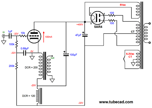
The LM317 has been replaced by an inductor (a choke) and its DCR combined with the output transformer’s primary’s DCR effectively create a 320-ohm cathode-bias resistor. An inductor functions much like a constant-current source to AC signals, as it opposes a change in current flow through it. The 5AR4 tube rectifier replaces the solid-state rectifiers and charges up the 47µF power-supply capacitor. Why so low a capacitor value? Too big a capacitor will damage the tube rectifier. Remember that the bigger the capacitor, the greater the peak charging current. The zener is no longer needed, although I would still use one, just to play it safe. In many ways, this topology is similar to the old single-ended, para-feed (choke-loaded, transformer-coupled) topology.
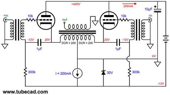
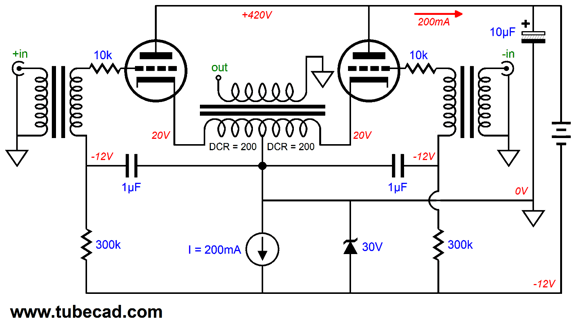
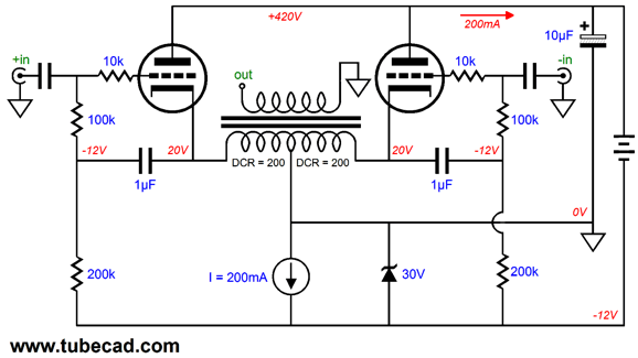
Push-Pull Inverted Auto-Bias
The constant-current source sets the idle current, with each output tube getting half, assuming matched tubes. In addition, the constant-current source filters away the power-supply noise. Because the constant-current source limits the maximum current flow, this amplifier must be run in strict, no nonsense, non-glossy-ad, real-thing, class-A mode. (The zener might actually help out here, as it could allow the amplifier to break out of the class-A envelope of operation and intrude into class-B territory, but at the cost of requiring some tweaking.) The output stage is configured as a push-pull grounded-cathode amplifier, not a cathode follower, appearances to the contrary. In other words, the same output impedance and voltage gain as if the output transformer had been located at the plates. The zener offer the same over-voltage protection for the constant-current source. The 100µF power-supply capacitor holds the 420V charge that defines the B+ voltage for the output stage. The two 300k grid resistors and the two 1µF decoupling capacitors are needed to provide a DC path to the -12Vdc and to tightly couple the isolation transformer’s secondaries to the cathodes. Remember that the output tube will produce gain, so if 30Vpk of signal goes in the primary, 300Vpk might develop at the cathode. One danger with any two-output-tube design, either PP or parallel SE, is that if one tube is missing from its socket while its brother is inserted, the engaged tube will conduct twice the idle current, which could damage the tube. The workaround is to place both output tube heaters in series and use a 12.6V (or 10V for 300B tubes) heater voltage. Thus, much like Christmas tree lights, if one tube is missing, the other will not heat up. Okay, here is your homework assignment: How could this circuit be reconfigured as a power cathode follower?*
Next Time
* Answer:
Mind you, the isolation transformers may not be needed, but truly huge input swings, say +/-300Vpk, will be. How does one get such a huge differential input signal? One solution would be to build an ES headphone amplifier, tube-based of course. And, of course, you could switch between driving ES headphones, such as those made by Stax, or driving the following cathode-follower power output stage, which in turn would drive speakers.
//JRB |
And
High-quality, double-sided, extra thick, 2-oz traces, plated-through holes, dual sets of resistor pads and pads for two coupling capacitors. Stereo and mono, octal and 9-pin printed circuit boards available.
Designed by John Broskie & Made in USA Aikido PCBs for as little as $24 http://glass-ware.stores.yahoo.net/
The Tube CAD Journal's first companion program, TCJ Filter Design lets you design a filter or crossover (passive, OpAmp or tube) without having to check out thick textbooks from the library and without having to breakout the scientific calculator. This program's goal is to provide a quick and easy display not only of the frequency response, but also of the resistor and capacitor values for a passive and active filters and crossovers. TCJ Filter Design is easy to use, but not lightweight, holding over 60 different filter topologies and up to four filter alignments: While the program’s main concern is active filters, solid-state and tube, it also does passive filters. In fact, it can be used to calculate passive crossovers for use with speakers by entering 8 ohms as the terminating resistance. Click on the image below to see the full screen capture.
Tube crossovers are a major part of this program; both buffered and un-buffered tube based filters along with mono-polar and bipolar power supply topologies are covered. Available on a CD-ROM and a downloadable version (4 Megabytes). |
|||


| www.tubecad.com Copyright © 1999-2012 GlassWare All Rights Reserved |