| John Broskie's Guide to Tube Circuit Analysis & Design |
02 January 2013 Happy New Year Sure the Mayans got it wrong about the end of the world, but they did get it right about the end of Twinkies. How many of you readers have friends who are shocked to learn that tubes are still being made and enjoyed? Recently, a friend of my wife got the giggles as she looked at the graphic emblazoned on my T-shirt, which she mistakenly believed to be an exploded view of the insides of a sex toy.
She was quite disappointed to learn that it was a diagram of a 6L6 tube.
Single-Ended Circlotron As I finished my last blog post, I realized that it could have gone on for twice as long, if not longer. The Circlotron circuit, like other circuits that hold a floating power supply, is ripe with potential to confuse tube newbies. My hope was that the following circuit, which I had shown in the last posting, would help many see that two output tubes were not required in the Circlotron.
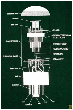
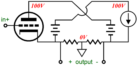
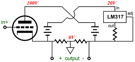
But this circuit might have just confused more readers than it helped. So, let's look into it a bit more carefully. The constant-current source can be made from triodes or pentodes or solid-state devices, such as bipolar transistors or MOSFETs or ICs or any combination of the above. Its only job is to provide a balancing current flow, so the outputs do not see any DC offset voltage; that's it. The 100V floating power supply could be replaced by a 200V or 20V floating power supply, depending on the maximum expected output-voltage swing.
How would the above schematic actually be built? Well, the easiest way would be to use an adjustable voltage regulator, such as the LM317, LM317-HV, or TL783.
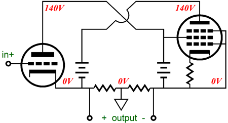
Of course, many find any solid-state device terribly gauche, so here is a pentode-based constant-current source.
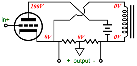
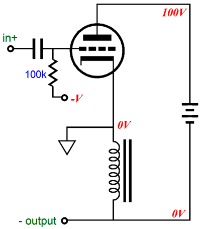
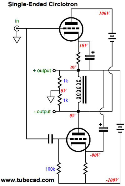
The constant-current source's job is to maintain a fixed current flow, so the DC offset is avoided. The single triode, on the other hand, does all the work of driving the load. The maximum peak current swing into the load is equal to the triode's idle current. Okay, now it's time to do some mental stretching. What happens if we use neither an active constant-current source nor its floating power supply? How would that be possible? Easy, we could use an inductor. Remember a perfect inductor offers no DC resistance, so it can displace no steady voltage.
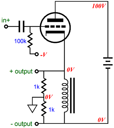
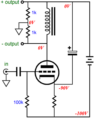
The inductor (choke) is the inverse of a capacitor. Where the capacitor resists a change in the voltage across it, an inductor resists a change in current flow through it. In the above circuit, the inductor will behave as loss-less constant-current source. (Of course, actual inductors that you can buy do present some DCR.) Before going any further, try to unravel the above schematic, seeing how the inductor is in parallel with the load, until you end up with the following identical circuit.
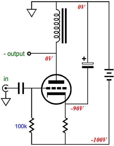
Yes, I know that it looks radically different, but the circuit is same (I added the input capacitor just to show how the triode would be biased; erase this addition from your mind, if you must). More importantly, it functions the same. There is no DC offset, because the inductor offers no DC resistance. Because the ground is located at the midpoint of the output, the circuit presents a two-phase output, with a plus and minus output, relative to ground. (Yes, a single-ended circuit can give rise to balanced outputs. Another example is the split-load phase splitter.) I know that 99% of readers falsely believe that the above circuit is a cathode-follower, with an output impedance equal to rp/(mu + 1). Sorry, but it is not a classic cathode-follower, as the ground is not located at the bottom of the inductor. Really, that makes a big difference? Yes, for example the output impedance of the above circuit is 2rp/(mu +2), which can be substantially higher than the classic cathode-follower's rp/(mu + 1). For example, given a triode with a mu of 10 and an rp of 1k, the above circuit will yield an output impedance of 166 ohms, whereas the below circuit, a true cathode follower, will yield on 91 ohms of output resistance. 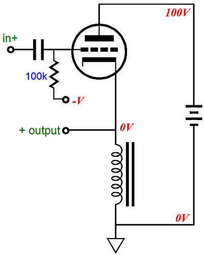
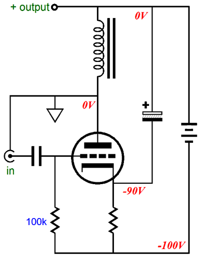
Now, what would happen if we attached the ground to the top of the inductor, where it meets the cathode?
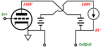
What we get is no longer a buffer, but an amplifier: an inverted single-ended amplifier, a grounded-cathode amplifier, that inverts the phase of the input signal at its output and which offers voltage gain (if the load impedance is higher than the rp). This amplifier's output impedance is equal to the triode's rp. We can go replace the inductor with a constant-current source (with its own floating power supply).
This is also an inverted single-ended amplifier that inverts the phase of the input signal at its output and which offers voltage gain. I would never call such a circuit a "Circlotron," finding the name "horizontal inverted single-ended amplifier" much better suited to the task of intelligently describing the circuit. In fact, I would prefer that we reserved the name "Circlotron" for only the original Wiggins circuit. So, the title of today's post is something of a lie, as ideally I would refer to the following circuit as a "horizontal push-pull mid-grounded buffer."
And, for example, I would refer to the next circuit as a "vertical push-pull mid-grounded buffer." The advertising department wouldn't approve, but both names are functional, if less snazzy.
In my Circlotron Relativity article, I mention the problem of naming circuits:
But all the toothpaste has been squirted onto the floor and no one is going to get it back into the toothpaste container anytime soon. Let's return to the single-tube "Circlotron" circuit, which used an inductor in place of the active constant-current source.
We have seen that where the ground, the circuits signal reference attaches makes a dramatic difference in the topology and performance of the circuit, transforming a Circlotron into a cathode follower buffer or into a grounded-cathode amplifier. Well, we are free to also transpose the inductor and the tube.
The above Circlotron performs identically to the previous circuit, although it looks radically different. (I switched to cathode-bias only to show the preferred way to bypass the cathode resistor in the real world; in the theoretical world, however, the bypass capacitor terminating into the -100V B- would work identically. Real-world power supplies are not perfect voltage source, as they come dirty with ripple and rectifier-induced noises.) This is buffer that offers balanced outputs and whose Zo equals 2rp/(mu + 2). We can move the ground to the triode's plate, creating a cathode follower (a GPK), whose output signal is in phase with the input signal and whose Zo equals rp/(mu + 1).
Or, we can can attach the ground to the top of the inductor, thereby creating a grounded-cathode amplifier, which offer voltage gain and whose Zo equals the triode's rp.
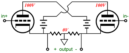
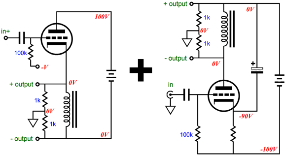
I know that I have made some big demands on many readers, as most believe that we have no liberty when it comes to ground. But you are free; you can place ground anywhere you please. As John F. Kennedy said, "Conformity is the jailer of freedom and the enemy of growth." Of course, there is no guarantee that the circuit will function as we hope, for we are free to make a total mess, which is an essential part of freedom. Enough preamble, here is the question: Can we wed the two following Circlotron circuits, creating a new one, which remains single-ended?
And if so, what do we get? Answer: a single-ended Circlotron that uses two tubes and two floating power supplies.
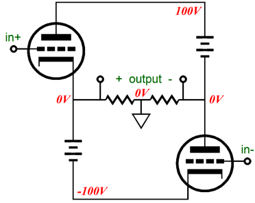
There is nothing push-pull about this circuit, as both triodes conduct in phase. My advanced students will quickly realize that the inductor is not needed and can readily be removed from the circuit. Indeed, we can abstract the above circuit into the following.
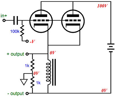
IMPORTANT PART: I am NOT recommending this circuit in the least. It is interesting, but not in any way sonically superior to the following circuit. Its only advantage is the elimination of the inductor, which is dubious, as the inductor serves as a safety device for the speaker, as it prevents a sustained DC current flow through the external load, much as a coupling capacitor would.
Okay, John, so why show us circuits that you do not recommend? Good question, as doing so is dangerous. Dangerous? Many readers of this blog do not speak English. They find my many schematics in Google searches and do not visit this web page directly, so they do not know the meta-information behind the schematic. Some non-English-speaking readers do run my words through Google Translator, but the results are far from perfect. (The advice given to all politicians—Never use sarcasm or irony in a speech or a debate or an interview, as out of context or by just appearing in print, you will get into a lot of trouble for something that you didn't mean— is good advice and, sadly, it applies to those who will have their words run through Google Translator as well.) The reason I show both poor and inspired circuits is to educate. I want the world to abound in educated, not indoctrinated, but cultivated, cultured, and learned audio-electronics practitioners. I do not want disciples; I want colleagues.
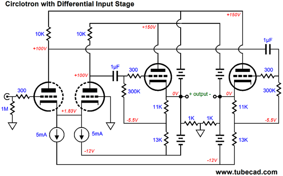
Circlotron with Differential Input Stage
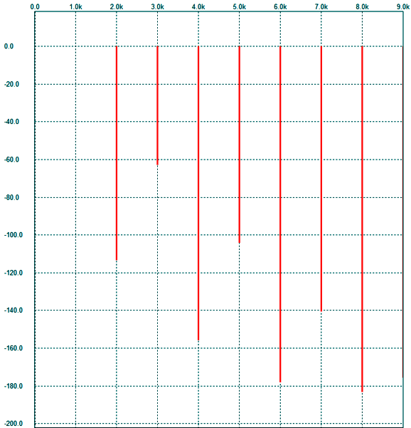
The input is shown as being unbalanced, but the input stage can readily accept a balanced input. The floating power supplies are bipolar with dissimilar voltage, +100V, 0V, and -12V. The -12V rails are used to set up a negative bias voltage for the output triodes and could also be used to heat the tube's heaters. The input stage uses two constant-current sources. Why? The two CCS prevent a DC offset from appearing at this Circlotron's outputs. Besides, they make for a beautiful symmetry. (I am tempted to quote Friedrich Schiller's famous remark about Grace being the beauty of form, but I have used up my allotment of quotes per posting.) This Circlotron looks NFB-free, but actually hold two negative feedback loops because of the input stage's plate resistors terminate not into a fixed B+ voltage, but two moving voltages. The schematic above assumes that the input tube is a 6CG7 or 6SN7 and the output tube is an ECC99. I ran some SPICE simulations on this circuit and with a brutally low 50-ohm load and 1Vpk at 1kHz, the following Fourier graph resulted.
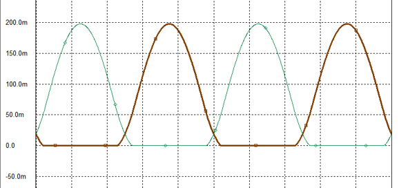
Not bad. The THD would come in at about 0.1%. (In fact, with a balanced input signal, the results are even more lovely. And with a 300-ohm load, much lovelier still.) And although the graph betrays a push-pull harmonic signature, the higher harmonics decrease in very single-ended-tube fashion. A very nice balanced tube headphone amplifier this is. At 10Vpk of output into 50 ohms, the distortion rises to about 1%. By the way, if we look at the current conduction through the two output triodes, we see class-AB operation.
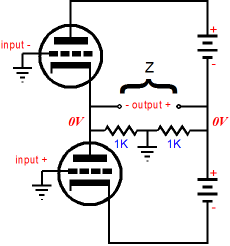
So, even with headphones, no free class-A operation results. The 19mA of idle current per output triode only yields 1.9Vpk of class-A output. Remember, with class-A push-pull amplifiers, the load must be factored in the evaluation. For example, with a 300-ohm load, this Circlotron can deliver 10Vpk of class-A output; with a 47k load, probably 100Vpk. Okay, John, another damn headphone amplifier; I only care about power amplifiers. Well, topology stands apart from the intended use. Given enough tubes and this topology, a shaker-table amplifier could be made that put out 2,500 Watts. The problem we face with a typical output tube from an OTL amplifier, such as the 6AS7 or 6C33, is its low mu and relatively low transconductance. In other words, these tubes will require huge input signals in order to be driven to full output. Thus, the following circuit would be a better choice.
This is a somewhat idealized version, as I would add some safety features and give each output triode its own 10-ohm cathode resistor. In addition, I would not terminate the 4.7µF capacitors to the top of the floating power supplies, but at the outputs. But these are subtleties; as it stands, the topology is sound.
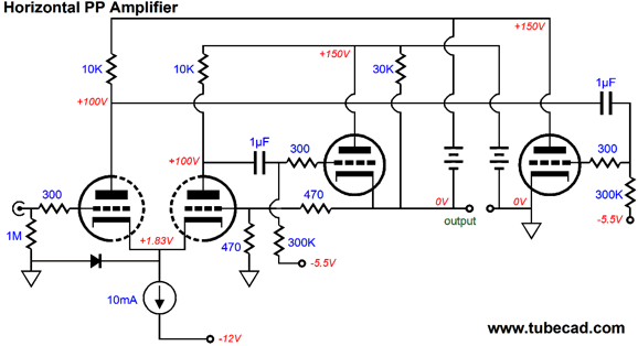
Horizontal Push-Pull Amplifier
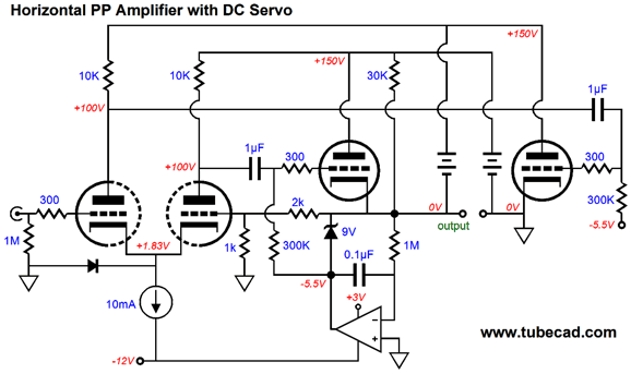
(The voltage values work with a 6CG7 or 6SN7 as input tube and an ECC99 as output tube. The intended use is a headphone amplifier, but it could also be used as a super-buffed line-stage amplifier. The idle current for each ECC99 triode is about 20mA.) Note the 30k resistor that attaches to the output. Why is it there? It is needed to prevent a small DC offset due to the differential input stage directly coupling to the output. This added resistor will impose a 5mA drag on the output, which will pull the output back up to 0V at idle. Of course, a coupling capacitor could be added. I certainly would, with any line stage amplifier I built; but with a headphone amplifier, the coupling capacitor would have to be huge. So, how can we make this amplifier both coupling-capacitor-free and safe, for example if the output tube is missing from its socket or has an open heater element? The answer is a DC servo, but not just any DC servo.
This DC servo controls the bias voltage presented to the left output tube, which will keep the output DC offset free at idle. In addition, it will force the output to center at 0Vdc, even if the output tube is missing. How so? The zener diode is normally reversed biased and falls out of the circuit. But if the tubes are missing, the OpAmp will sense at the output has gone positive for too long and will the OpAmp's output will slam negative, which will engage the zener, which will pull the output back to 0V. This is not perfect, as the amplifier's output voltage swing is limited by the zener voltage, so a maximum of about 3.5Vpk is possible, although the ECC99 could swing much more, even into a 50-ohm load. The best workaround might be to use the following circuit instead.
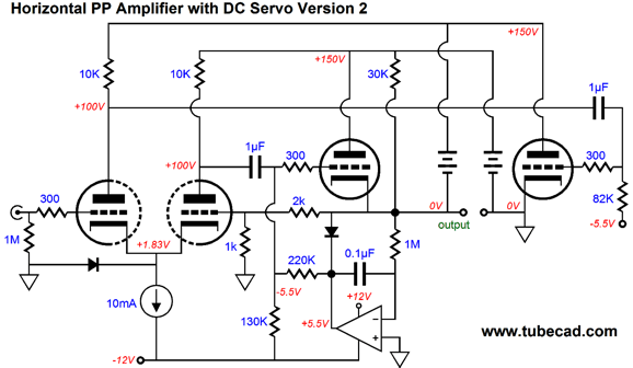
The zener diode has been replaced by a simple diode, such as a 1N4001. The two-resistor voltage divider sets the same -5.5V bias voltage, but it does so by having the OpAmp's output sit at +5.5V. Should the amplifier's output drift up off 0V for a prolong period of time, the OpAmp will slam negatively, causing the diode to become forward biased, allowing it to conduct and pull the output back down to 0V. Let's be frank: DC coupling with tube circuits is scary, because of the high voltages and because the tubes can be absent from their sockets or loosely seated. The best approach would be to use both a DC servo circuit and a window voltage comparator circuit and a relay to protect the load. The Circlotron version of this circuit is intrinsically safer, as it presents balanced outputs. Thus, as long as both outputs hold the same DC offset, the load is safe. Actually, the load is safe if and only if it makes no connection to ground, as a balanced power amplifier's inputs would. On the other hand, this circuit offers a lower output impedance due to its running the output tubes as cathode followers and due to the negative feedback loop into the differential input stage, sets a fixed voltage gain of about 3.
Next Time
//JRB |
I know that some readers wish to avoid Patreon, so here is a PayPal button instead. Thanks.
John Broskie
Kit User Guide PDFs
And
High-quality, double-sided, extra thick, 2-oz traces, plated-through holes, dual sets of resistor pads and pads for two coupling capacitors. Stereo and mono, octal and 9-pin printed circuit boards available.
Designed by John Broskie & Made in USA Aikido PCBs for as little as $24 http://glass-ware.stores.yahoo.net/
The Tube CAD Journal's first companion program, TCJ Filter Design lets you design a filter or crossover (passive, OpAmp or tube) without having to check out thick textbooks from the library and without having to breakout the scientific calculator. This program's goal is to provide a quick and easy display not only of the frequency response, but also of the resistor and capacitor values for a passive and active filters and crossovers. TCJ Filter Design is easy to use, but not lightweight, holding over 60 different filter topologies and up to four filter alignments: While the program's main concern is active filters, solid-state and tube, it also does passive filters. In fact, it can be used to calculate passive crossovers for use with speakers by entering 8 ohms as the terminating resistance. Click on the image below to see the full screen capture.
Tube crossovers are a major part of this program; both buffered and un-buffered tube based filters along with mono-polar and bipolar power supply topologies are covered. Available on a CD-ROM and a downloadable version (4 Megabytes). |
|||


| www.tubecad.com Copyright © 1999-2013 GlassWare All Rights Reserved |