| John Broskie's Guide to Tube Circuit Analysis & Design |
28 January 2013  Aikido Push-Pull Revisited
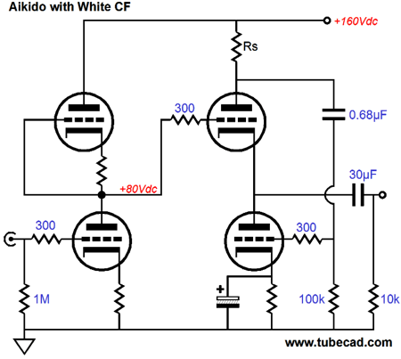
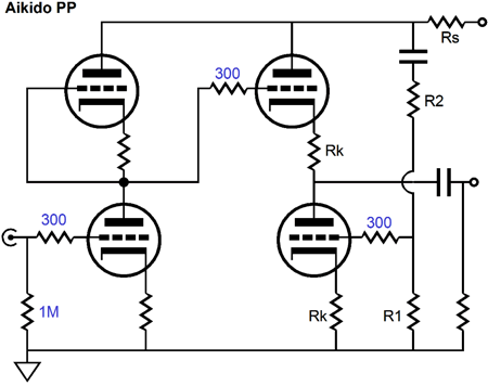
Not completely forgotten, for I had altered many of my Aikido PCBs to conform to this topology, the topological change of having the sense resistor appear ahead both the input and output stages. Why did I make that change? This topology results in much better performance than the following circuit, which places only the White cathode-follower output stage, not the grounded-cathode input stage, under the influence of the sense resistor, Rs.
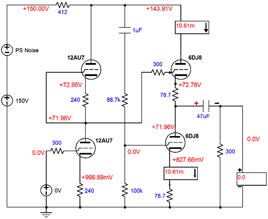
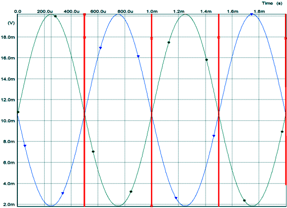
(Do not be misled into believing that the bypassed cathode resistor in the above circuit is the key difference; it's not. The Aikido PP circuit shown before it can also forgo the top cathode resistor and use a bypassed cathode resistor at the bottom. No, the key difference lies in having the entire circuit work in series with the sense resistor and the single 100k resistor that attaches to the 0.68µF capacitor.) After I ran some SPICE simulations, I saw why I had been so impressed with this Aikido PP topology, as it offered fantastically good PSRR and excellent balance in current swings between top and bottom output triodes, as they worked into the 300-ohm load. The following SPICE graph shows just how good the balance is.
How does this old SPICE circuit differ from the Aikido PP topology that was shown in Blog Numbers 221 and 224? Note that this old SPICE-drawn schematic holds a two-resistor voltage divider that feeds the bottom output triode its input signal, whereas the the Aikido PP topology that was shown in Blog Numbers 221 and 224 used no voltage divider.
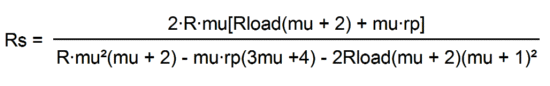
Is this a big deal? Well, yes and no. If the following formula scares you, it is a big deal.
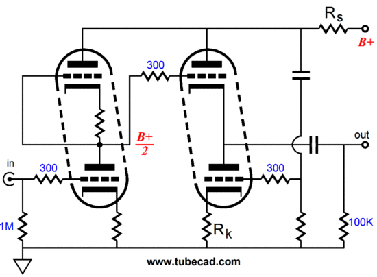
where R = rp + (mu + 1)Rk and the rp and mu belong to the input triodes, which makes the above formula even more formidable. In contrast, we can ignore the input triodes with the older Aikido PP topology, the one with the two-resistor voltage divider. So, the two important features of this topology are the two-resistor voltage divider and the sense resistor (Rs) being fed from both the input and output stages.
Okay, how do we design an Aikido Push-Pull amplifier based on this topology? The first step is setting the two-resistor voltage divider values, which will null the power-supply noise from the output. Pick a value for resistor R1, say 100k. Next, use the classic Aikido formula: R2 = R1(mu - 2) / (mu + 2) Where mu is the amplification factor of the output triode. For example, the 6DJ8 holds a mu of 33, so R2 = R1(33 -2) / (mu + 2), which with R1 equal to 100k makes R2 equal to 88.6k. Since 1% resistor values don't offer an 88.6k resistors, we use a 88.7k resistor instead. This formula works regardless of the value of the series sense resistor (Rs), whether or not we use bypassed cathode resistors. The next step is to work out the sense resistor value. If the top cathode resistor is replaced by a shunting piece of wire and the bottom cathode resistor is bypassed (or is also omitted and a negative grid-bias voltage used), the following formula is used: Rs = (R1 + R2)(rp + 2Rload) / muR2, where Rload equals the load impedance. On the other hand, if unbypassed top and bottom cathode resistors are used, as shown in the schematic above, then the following formula is needed: Rs = (R1 + R2)(rp + (mu + 1)Rk + 2Rload) / muR2 Not that bad, as I can almost do the math in my head. Sure, in your mind. (In fact, I am often surprised by how often simple math eludes me, but something as hairy as the above formula can be performed unconsciously; not perfectly, but darn close.) The question unanswered, Why didn't I post this flavor of Aikido Push-Pull topology and its required math four years ago after my experiments in SPICE? I don't know why for sure, but I probably got distracted by something else and I forgot about the results, except for remembering that this change in topology needed to be included in new production runs of my PCBs.
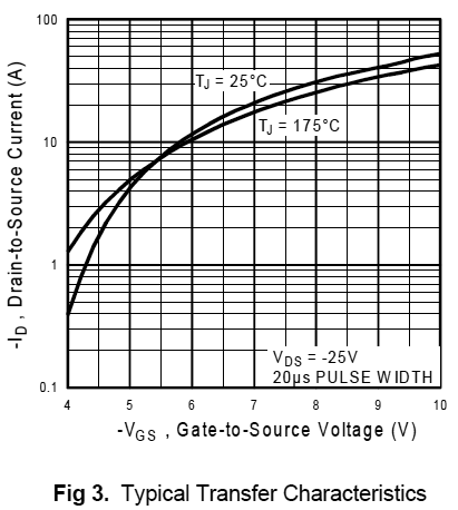
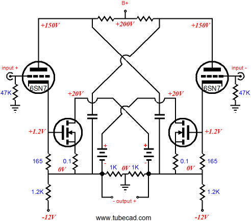
Solid-State Circlotron The Circlotron topology is not limited to vacuum tubes, as solid-state devices, such as FETs, transistors, IGBTs, and MOSFETs can be used. Indeed, the vacuum tube is a very poor choice for driving an 8-ohm loudspeaker without a step-down output transformer. Why? The tube works well with high-voltages and low currents, just the opposite of what 8-ohm speakers require. On the other hand, if high-quality 600-ohm—or even 100-ohm—loudspeakers were available, then tubes would prove an ideal match. Here’s an example: the 6AS7 is a low-voltage power triode that can pour forth a great gush of current, for a tube that is. With a grid-voltage of 0V and cathode-to-plate voltage of 56V, the 6AS7 triode will dissipate 13W and draw 230mA of current. You can readily see why this triode was used as the pass device in many high-voltage regulators 50 years ago, as that is an amazing amount of current flow for so little plate voltage. But 230mA of current only buys you 0.21W into an 8-ohm load. Using eight 6AS7 triodes in parallel only brings the wattage up to 13.5W, but at a cost of 20A of heater current and 126W of heater heat. Wait a minute, there many OTL amplifiers that use four to eight 6AS7 tubes and they put out much more than 13.5W. Indeed they do, but only by exceeding the triode’s plate dissipation limit and/or running into positive grid voltages. Of course, most musical playback only requires brief excursions into high wattage, so overdriving these triodes is neither so reckless nor so dangerous as we might imagine. Nonetheless, tubes are still a fantastically poor match for 4- or 8-ohm loudspeakers without a tapped inductor or step—down output transformer. Solid-state devices, in contrast, can swing huge amounts of current, amperes and amperes, with very little voltage across the devices. In addition, they can do so with very little input signal prompting. For example, a triode with a transconductance of 10mA/V is considered to be a high-transconductance tube, but a power MOSFET with a transconductance of 10A/V is not exceptional; and 10A/V is 1,000 times greater than of 10mA/V. Thus, if our high-transconductance triode sees a 0.1V increase in grid voltage, its conduction increases by 1mA; if the MOSFET sees the same 0.1V increase in gate voltage, its conduction increases by 1A! Now you know why 99.999% of hybrid power amplifiers use a tube-based frontend and a solid-state-based output stage. I fondly remember the first MOSFET-based power amplifier that I built back in the late 1970s. It used BD512 and BD522 MOSFETs and delivered about 15W into an 8-ohm load. (I used two N-channel devices and three P-channel MOSFETs, as this ratio helped match the transconductances between N and P devices.) I clearly remember working to establish the desired idle current through the output devices and my being surprised to see the huge swings of current flow from the smallest adjustment of the bias-trim potentiometer, as I was used to sloppy old 6L6 and KT88 power tubes. (My workaround was to place two resistor in series with the potentiometer, one above and one below, so a much smaller voltage adjustment was possible.) MOSFETs may be somewhat like tubes in that they are easier to drive, but in every other respect they are more like bipolar transistors. True some power MOSFETs do exhibit a negative temperature feature wherein they conduct less current the hotter they get, in contrast to transistors which exhibit a positive temperature relationship, conducting more, the hotter they become.
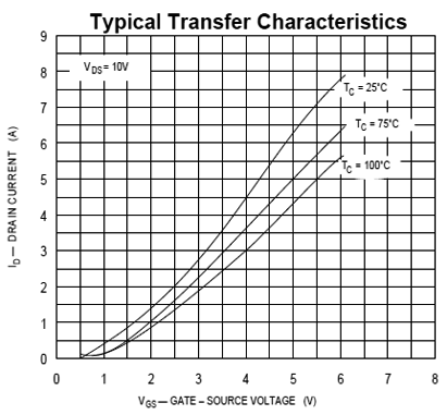
Note how the hotter the MOSFET gets, the lower its current conduction. But many do power MOSFET do not go negative until many amperes of current flow through them. For example, the IRFP9140 doesn't go negative until about 7amps of current is reached, by which time the device has melted. And down at 100mA, where its idle current resides, it exhibits a strong positive temperature coefficient.
Thus, if you decide to forgo the idea of building a 200lbs power Circlotron amplifier that sports twenty 6AS7 triodes per channel and instead opt for just a pair of N-channel MOSFETs, then the issue of setting the idle current might prove more difficult than you expected. (By the way, Microsemi.com offers a good tutorial on MOSFETs: 14692-mosfet-tutorial.) Note how increasing the MOSFET's gate voltage by just +1V results in such a large increase in current conduction. True, adding a source resistor will greatly slow down the power MOSFET’s gate sensitivity, as the MOSFET’s effective transconductance with an unbypassed source resistor is: gm' = gm / (1 + gmRs) For example, a MOSFET with a raw transconductance of 10A/V will see its transconductance fall to 3.125A/V, with the addition of a 0.22-ohm source resistor. But even compared to ten 6AS7 triodes in parallel, this is still a screaming amount of transconductance, as a 0.1V change in gate voltage will result in a 312.5mA change in idle current. I want you to keep all this in mind as you look at the following schematics.
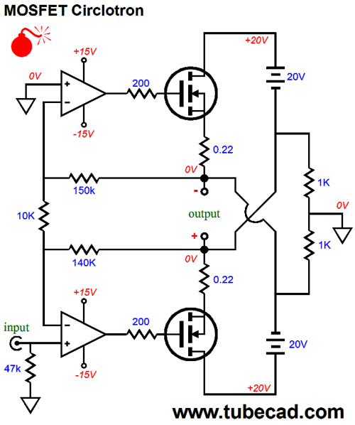
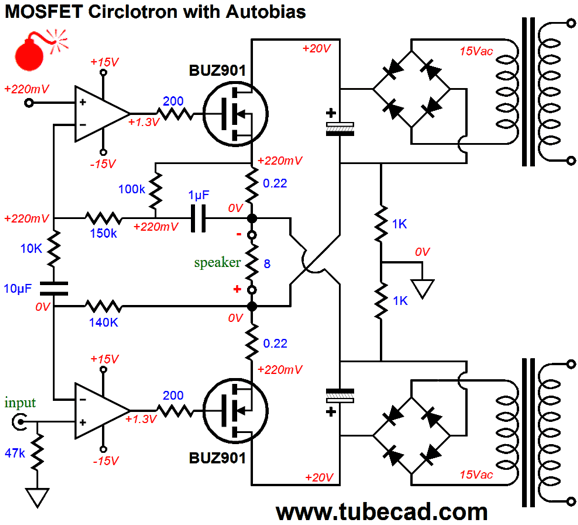
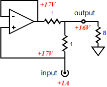
A bomb? Sure this Circlotron circuit looks both simple and functional. The two OpAmps control the two N-channel MOSFETs, providing both their needed input signals and DC offset elimination. So what’s not to like? True, the OpAmps will strive to keep this Circlotron’s DC offset to a minimum, but what will the MOSFET’s idle current be? 10mA? 100mA? 10A? 100A? Who knows? As long as both output MOSFETs draw an equal idle current, there will be no DC offset. But just what the idle current will end up being is not set with this circuit. A workaround is to use coupling capacitors and two adjustment potentiometers.
Each MOSFET gets its own bias adjustment circuit and trim potentiometer. In addition, the OpAmps do not see the Circlotron’s output in their feedback loops, so they no longer control the MOSFET’s output. This can be seen as being either a good thing or a bad thing, depending on your views on negative feedback. The bigger problem is that setting the idle current and DC offset will be something of a pain, as both targets move at once. The following variation lets the bottom OpAmp control the DC offset by making sure that the bottom MOSFET’s idle current equals the top MOSFET’s idle current.
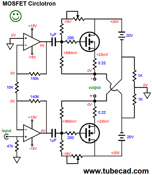
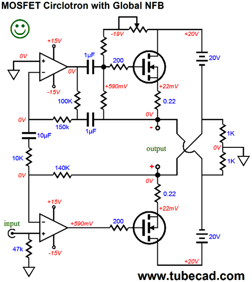
Much like the circuit that preceded it, this Circlotron does not use a global negative feedback loop that reaches the amplifier’s output. The OpAmps put out a balanced set of output signals and the power MOSFETs try to follow them as best they can. Once again, this can be seen as either being a feature or a liability, depending on one’s perspective. If we do want a global negative feedback loop that extends to the amplifier’s output, then the following circuit will achieve this goal.
The top OpAmp sees the inverted output through the bottom 1µF coupling capacitor; the bottom OpAmp sees the non-inverted output directly through its 150k feedback resistor. The potentiometer still sets the idle current and the bottom OpAmp will take care of the DC offset by establishing the matching idle current flow through the bottom output MOSFET. I should mention is the 140k and 150k feedback resistors in these circuits. Why do they differ in value? The top OpAmp functions as an inverting amplifier, whereas the bottom OpAmp functions as a non-inverting amplifier. Thus, the top OpAmp’s gain equals 150k/10k, whereas the bottom OpAmp’s gain equals (140k + 10k)/ 10k, which results in a gain of 15 for both OpAmps. But as the two OpAmps put out a balanced output, the voltage gain the loudspeaker sees is equal to 30; in other words, 1Vpk of input signal will result in 30Vpk of output signal into the external load resistance. In the case of an 8-ohm load, 30Vpk equals 56W, as W = Vpk² / 2Rload. Now, the question is can we lose the potentiometer and let the OpAmps take care of both setting the idle current and eliminating the DC offset? The following Circlotron circuit endeavors to do both tasks, but fails.
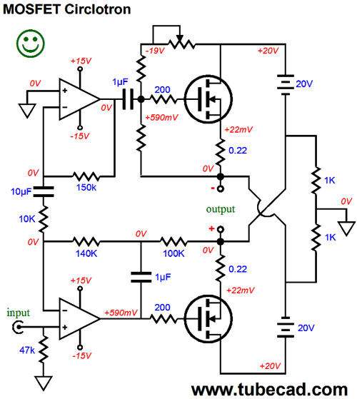
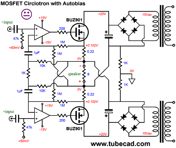
Although it looks reasonable enough, this circuit doesn't work once the amplifier leaves its class-A range of operation. Note how the top OpAmp’s non-inverting input no longer attaches to ground, but to a reference voltage, in this case 220mV, which will be imposed across the 0.22-ohm source resistors, resulting in a heavy idle current of 1A. The bottom OpAmp will strive to eliminate the DC offset by ensuring that both MOSFETs draw an equal idle current. Both OpAmps include the Circlotron’s output in their negative feedback loops, so the OpAmps control the MOSFETs' output. But once the class-A envelope of operation is exceeded, the 1µF begins to charge up due to rectification effects caused by the 0.22 source resistor voltage drop exceeding 0.44Vpk during high-output operation. The following workaround that I have come up with requires a balanced input signal. In addition, two extra 1M resistors have been added, which work to undo much of the rectification effects. So where is the smiley face? Although this circuit has passed the SPICE tests, it hasn't been built and tested in reality. It is quite possible that long, sustained organ notes or droning sympathizer bas will eventually overthrow the auto-bias aspect of the circuit, resulting under-biased MOSFETs, which although much more preferable to over-biased MOSFETs, is still a defect.
I must mention that in all the above schematics, the OpAmps have been powered by a fixed +/-15Vdc bipolar power supply that does not float, as the two 20V power supplies do, but is grounded. The assumption was that lateral power MOSFETs, such as the BUZ901 would be used. If the cheaper and more-readily-available MOSFETs, such as the IRFP140, are used, then the OpAmp power supply must hold higher rail voltages, say +/-18Vdc to +/-20Vdc, as these MOSFETs require higher turn-on (threshold) voltages at their gates.
Broskie Remake of an Existing Circlotron Amplifier
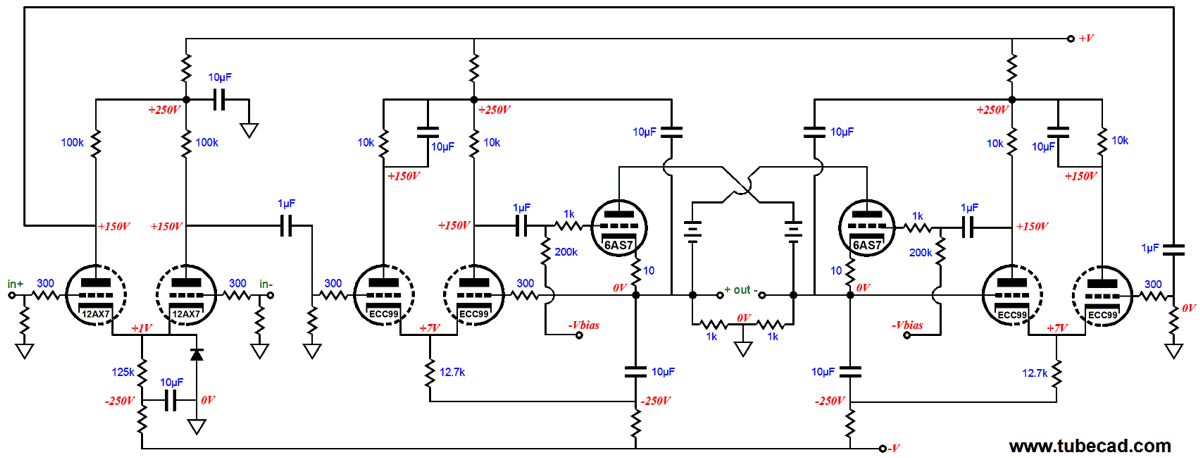
Beginning at the input, t he 12AX7-based input stage uses a differential amplifier to provide the needed voltage gain, while the ECC99-based driver stages control the output tube's output. As I look at it, I see that the 12AX7 might provide too much gain, so a better choice might be a 12AT7 or 5965.
IMC and Hybrid Circlotron
The IMC could also be thought of as being a current-doubler circuit, doubling the current delivered by the external power amplifier. The external amplifier puts out 2A and the load sees 4A of current. Well, back in Blog Number 178, I showed this schematic:
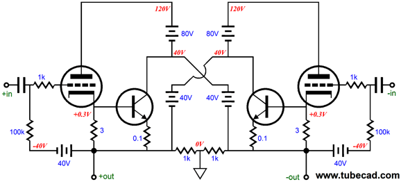
This Circlotronesque output stage uses large-valued capacitors instead of floating power supplies for the triodes and two floating power supplies for the MOSFETs. It also uses a wimpy triode, the 6SN7, to both drive the 8-ohm load and the power MOSFETs. Yes, the 6SN7's current contribution is small, 1650 times smaller than its partner MOSFET, but it nonetheless does add to the output. The following schematic from Blog Number 250 shows a hybrid Circlotron, wherein the tube does more work in driving the 8-ohm load—55 times more than in the previous example, as its 3-ohm cathode resistor is 30 times bigger than the NPN transistor's emitter resistor, which implies 1/30th the current contribution by the tube.
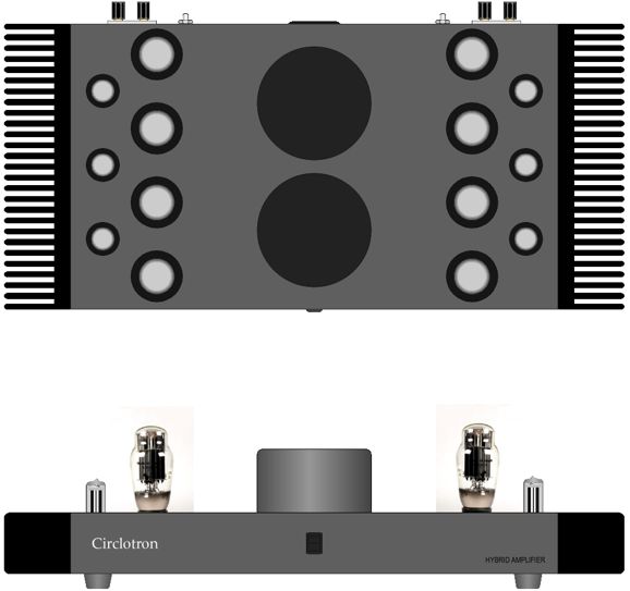
Okay, now imagine that the triode's cathode resistor is only 4 times larger in value than the NPN transistor's emitter resistor, which would imply that the triode would do 1/4th the work that the transistor does and that the 8-ohm load would appear as an 40-ohm load (five times bigger). Now, 40-ohms is still far too brutal a load for any triode, so imagine four times more triodes and transistors in parallel on each side of the load, so the effective load impedance that each triode sees is 160 ohms. Now we are talking, as a 6AS7 can drive a 160-ohm load. For example, a peak of 200mA equals a peak voltage of 32V with a 160-ohm load. (32Vpk into an 8-ohm load equals 64W of power.) I am going to leave all the technical details for next time, but here is what such an amplifier could look like (in a stereo version). The big round cans hold toroidal power transformers. The heatsinks cool the eight power transistors per channel. Such a Circlotron amplifier could easily put out 6oW, even with conservative operation of the 6AS7 triodes, say 200mA peak output current and no positive grid voltages.
Next Time
//JRB |
I know that some readers wish to avoid Patreon, so here is a PayPal button instead. Thanks.
John Broskie
Kit User Guide PDFs
And
High-quality, double-sided, extra thick, 2-oz traces, plated-through holes, dual sets of resistor pads and pads for two coupling capacitors. Stereo and mono, octal and 9-pin printed circuit boards available.
Designed by John Broskie & Made in USA Aikido PCBs for as little as $24 http://glass-ware.stores.yahoo.net/
The Tube CAD Journal's first companion program, TCJ Filter Design lets you design a filter or crossover (passive, OpAmp or tube) without having to check out thick textbooks from the library and without having to breakout the scientific calculator. This program's goal is to provide a quick and easy display not only of the frequency response, but also of the resistor and capacitor values for a passive and active filters and crossovers. TCJ Filter Design is easy to use, but not lightweight, holding over 60 different filter topologies and up to four filter alignments: While the program's main concern is active filters, solid-state and tube, it also does passive filters. In fact, it can be used to calculate passive crossovers for use with speakers by entering 8 ohms as the terminating resistance. Click on the image below to see the full screen capture.
Tube crossovers are a major part of this program; both buffered and un-buffered tube based filters along with mono-polar and bipolar power supply topologies are covered. Available on a CD-ROM and a downloadable version (4 Megabytes). |
|||


| www.tubecad.com Copyright © 1999-2013 GlassWare All Rights Reserved |