| John Broskie's Guide to Tube Circuit Analysis & Design |
31 October 2013
Although I wrote this post before Halloween, I had run out space at my server, so I couldn't post it on time. Nonetheless, I like the above image (that I created last year) too much not to use it again this year, so the date remains unaltered.
Cornell Dubilier 1kV 1µF Polypropylene Film Capacitor
Just as we do not see the blind spot in each eye's field of vision, our ears and brain fill in what we know is there but fail to perceive. Here is an example, long ago, it was discovered that music should never be used in testing someone's hearing ability, as the brain fills in too much. For example, test subjects, wearing headphones, were told to raise their hand when the music stopped playing, then the tester kept lowering the volume. Many never raised their hands, however, even when the music had been completely turned off, the amplifier disconnected from the wall socket, the headphone plug pulled from its jack. What was going on here? The brain knew the piece of music well and kept it going in the absence of actual aural stimulation. Thus, the supremely difficult task of evaluating audio equipment. One British audio reviewer has come up with his own workaround: he evaluates gear exclusively with American country music. Why? Because he passionately hates American country music, so he is never seduced by the music. Of course, and for the very same reasons, an audio reviewer from Nashville might choose British symphonic works as his preferred testing music. Back to coupling capacitors, several days of shoot-outs had passed, made easier by the use of my capacitor-selector switch, and I finally soldered the Cornell Dubilier capacitor in place, but I didn't rush to listen to them; instead, I let them bathe in the line stage's high voltage and I went off to do other tasks. A few hours later, I remembered the task of evaluating the capacitors, so in another room, I configured the computer to stream the audio signal. Wow, even from the other room, I could hear something different, which I didn't expect and which made me nervous. So, for the next few days, I ran more shootouts and listened carefully. My conclusion was that I liked the Cornell Dubilier capacitor a great deal, as they did not annoy my ears with that typical polypropylene metallic sound (which some audiophiles love by the way).
The 1µF/1kV capacitors are 26 mm in diameter and 46 mm in length, with solid copper leads. They are now being offered for sale with my PCBs and kits at the Yahoo-GlassWare store for $17 for a pair (a nice price for a nice capacitor). 2017 Update: I am now stocking and selling the 942C series od CDE capacitors, as they sound even better. The downside is that they are even bigger, 30 mm in diameter and 53 mm in length; additionally, they cost $20 the pair. Still extremely inexpensive considering the performance.
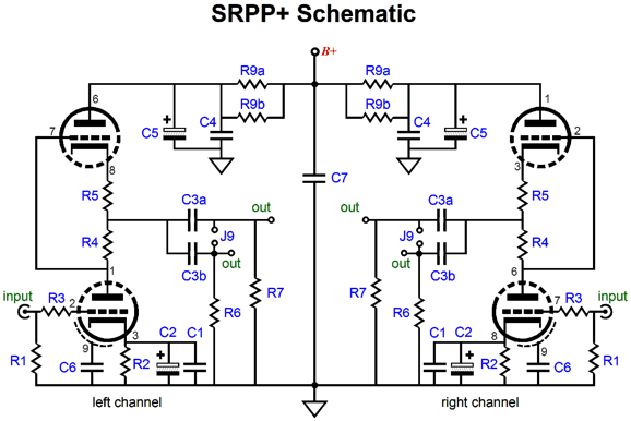
SRPP and Grounded-Cathode-Amplifier Disambiguation
In other words, replace resistor R5 with a jumper wire and you create a classic SRPP circuit; use resistors R4 & R5 and you create an SRPP+ circuit; and replace resistor R4 with a jumper wire and you create grounded-cathode amplifier with an active plate load resistance circuit. (By the way, at the RMAF, I was told again that I offer far too many options, that most prefer no options, as it frees them of the fear that they might have made the wrong choice. But this runs counter to my personality and philosophy, for I relish options; the more, the better. Think about it; other than a cremation urn, when does one size actually fit all? I am tempted to stand up indignantly and loudly proclaim in the fashion of Charles Ives, "Open your imagination and solder like a man!")
Current-Out Circlotron My guess is that what we—we being the audiophile world—really need is a loudspeaker that thrives on current-out. What might such a speaker look like? My guess is that it would be a super-low impedance ribbon or planar speaker, much like the old Apogee designs. Imagine a speaker with a 1-ohm impedance, a flat 1-ohm impedance. Such a load would destroy most solid-state amplifiers, as 99.9999999% of of power amplifiers are voltage-out devices. A current-out amplifier, on the other hand, would prefer this brutally low impedance load, as its ideal load is zero ohms. As Henry David Thoreau might have put it,
Think about it, the reason most speakers present an 8-ohm impedance is to keep the power amplifier happy, as the 8-ohm load sets a limit to the current flow from the amplifier. The problem with this approach is that is wasteful, as the 8 ohms of resistance begets heat, which if high enough, will melt the voice-coil's insulation, causing a short that will at least blow the amplifier's fuses, more likely its output devices. (The transistor has been defined as being a fuse-protection device.) It is the current that flows through the voice-coil enmeshed in the magnetic flux that moves the speaker diaphragm, as the following formula makes clear. F = B·l·i Where B is the magnetic flux density; l the wire length in the magnetic field; and i is the current flow. Notice that Voltage and Resistance do not appear in the formula. This makes sense, as a static voltage, no matter how high, cannot produce force in the presence of a magnetic flux; only current works with a magnetic flux to create force. So, for example, a voice-coil wound with super-conducting wire would still produce sound, yet offer no resistance, as the current flow would nonetheless react with the flux, creating a force that will move the speaker's diaphragm. And if there is no resistance, there can be no voltage drop. Of course, current also equals voltage divided by resistance, i = V/R, so i could be replaced by V/R in the formula, but it is still the current flow that matters. Given the same magnet structure, 16-ohm voicecoil with 16 volts across it will experience the same force as an 8-ohm voicecoil with 8 volts across it and, while we are at it, as a 4-ohm voicecoil with 4 volts across it or a 1-ohm voicecoil with 1 volt across it, as all see the same current flow of 1A. Thus, the 8-ohm impedance acts as a sort of voltage-to-current converter. Unfortunately, the typical speaker does not perform this task as linearly as we would like. Moreover, the 8-ohm load tradition has dug a deep rut that few acknowledge as being a rut, falsely seeing it as just the way things must be. (Yet, 2-ohm subwoofers are made, for use in cars as the target application, as car amplifiers have limited voltage available to them and the usual silly waste of power cannot be tolerated. In fact, I have seen some truly interesting car power amplifier schematics; interesting schematics are something amazingly rare, as 99% of solid-state power are the based on the same old topology.) Think about this: the big problem in creating a useable planar speaker lies in getting the impedance high enough to be used with existing voltage-out amplifiers, say at least 4 ohms. But what if we had the opposite goal in mind: getting the lowest possible impedance, which would be relatively easy, as copper foil conducts quite well and offers little resistance. The lower the resistance, the lower the heat, so more current can flow, increasing its efficiency. In addition, the lower the resistance, the lower the required rail voltages. A 1-ohm loudspeaker could equally thunder with 1/√8 the rail voltages that an 8-ohm speaker would require. Imagine a 200W solid-state power amplifier with only +/-22V rails, which would be possible with 1-ohm speakers.
Because current-out amplifiers are the inverse of voltage-out amplifiers, dead short loads are welcome, but open loads are feared. In contrast, if a modern solid-state voltage-out power amplifier sees a dead short across its output terminals, watch out, as it is going to be plenty unhappy, due to its failed attempt to bring the output voltage up to the dictates of its fixed voltage gain and input signal level. A current-out amplifier, in contrast, will attempt to establish the expected current flow into the open load impedance. The only way it do this is by throwing its output voltage high. If it could, it would swing infinitely high. Mind you, even with +/-70V power-supply rails, infinity is not likely to be reached. In fact, +/-69Vpk would be impressive. Note the difference between the current-out amplifier throwing its output voltage to the rail voltage and a voltage-out amplifier dumping all its available output current into a dead short. Which is more likely to damage the amplifier? Not the current-out amplifier. So what if the current-out amplifier output gets stuck at the rail voltage; as long as no current flows into the absent load resistance, the output devices are still safe. In addition, the output device would see very little voltage drop and little current flow, so the only damage possible is by exceeding the output device's gate-to-source or base-to-emitter voltages.
With tube-based, transformer-coupled, current-out amplifiers, on the other hand, the output transformer can cause real problems, if the connection to the speaker is broken during a loud passage, as the primary can swing mega-huge voltage spikes that can arc across the output tube. Fortunately, the output transformer's imperfections usually limit the ensuing voltage spike. The solid-state, voltage-out amplifier isn't nearly as lucky, when faced with a dead short, as its engaged output device(s) will see the full rail voltage and experience the full current flow that the device might muster before the fuse blows. How much current is that likely to be? Just look at the data-sheet of any modern power transistor or MOSFET. There you will read dizzying numbers, such as 33A for the IRFP250, which is the continuous figure, with the peak figure being closer to 100A! Now, 100A against a 70V rail voltage equals 7,000W of dissipation. Whoa! That's a lot of power for a 180W device to sustain, even for a millisecond.
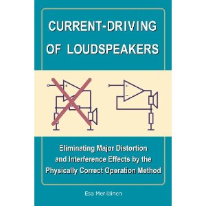
I have been rereading Esa Meriläinen's excellent book, Current-Driving of Loudspeakers: Eliminating Major Distortion and interference Effects by the Physically Correct Operation Method. I encourage to check this book out, even if you have no interest in current-out amplifiers, as it provides a fine overview of the design issues related to speaker drivers, crossovers, and amplifier design. In addition, he wrote an interesting chapter titled, Myths and Attitudes, which includes the following topics:
Think about this: Meriläinen will probably make less money from the sales of his book than makers of $20,000 power amplifiers will make from the sale of one amplifier. Yet, his efforts might redirect the future of amplifier and speaker design, which could render the $20,000 amplifier an interesting historical piece, but not something a serious audiophile would want to listen to in his system.
Designing a Current-Out Circlotron
Unfortunately, I approached the current-out Circlotron from the wrong way: I looked at a conventional Circlotron and wondered how to force it into current output; in vain. I needed to start with a fresh beginning, not at the preexisting end. Here is where the abstract notion of an idealized OpAmp came in handy. How does an idealized OpAmp differ from the real OpAmps that you can actually buy from Mouser or Digikey? The idealized OpAmp doesn't exist in reality, being a just a collection of desirable attributes and fixed operational functions. The key word in that last sentence was "operational," which means it functions in a specified sequence and in accordance with specific rules. The ideal OpAmp's functions are only two:
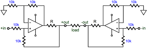
Its restricting rules or defining characteristics are: • Infinite input impedance Of course, there are more implied defining characteristics, such as the ability to swing both infinite voltage and current and to withstand infinite dissipation if need be; moreover, it should be capable of infinite slewrate. And, of course, no real OpAmp comes close to this ideal, when judged by these ideal standards; but when judged by actual grubby, everyday use, the modern solid-state OpAmp comes darn close to the ideal. As they say, it's certainly good enough for government use. Well, how would I design a differential current-out Circlotron with idealized OpAmps? The Howland current-pump circuit immediately came to mind and soon afterwards the following circuit.
A differential (balanced) input signal is applied and a differential output current is delivered into the load resistance. This being a current-out amplifier, the output current is fixed regardless of the load impedance, even if the load impedance is only 1 ohm or 0.1 ohms. In addition, because this is a current-out amplifier, the output impedance is infinitely high, so its damping factor is effectively zero, zilch, nada, which is precisely what we want. We have all heard of I-to-V converter circuits that follow DACs; well, this is a V-to-I converter, a balanced/differential V-to-I converter. A balanced input voltage goes in and a differential output current swing is created. So, given that it is a converter circuit, what is its conversion ratio? The answer depends on the value of the resistors labeled "R." If their value is 1-ohm, then the ratio will be that 1V in results in 1A of output current; if 0.5 ohms, then 2A. Ideally, +/1Vpk of balanced input signal should bring the amplifier to full output. When inspecting a voltage-out amplifier's operation, it's useful to start with an infinitely high load impedance. But when inspecting a current-out amplifier, it's useful to start with a dead short; i.e. zero ohms.
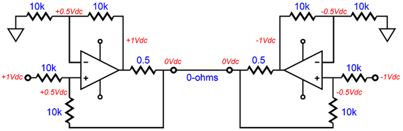
The idealized OpAmps do everything that can to ensure that their inputs always see the exact same voltage, which is only possible with the above voltage and current relationships. It may look like the jumper-wire load sees no current flow, as it sees no voltage differential. But this assumption is wrong, as the jumper-wire is in series with the two 0.5-ohm resistors and the +/-1V outputs from the OpAmps. Thus, it experiences a current flow of 2A, which implies a conversion ratio of 1V to 2A. Now, let's replace the jumper-wire with an 8-ohm load.
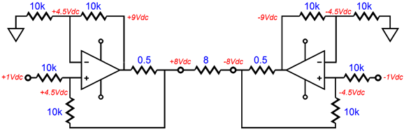
The same fixed current output obtains, 2A, although all the internal voltages have changed. If a 4-ohm speaker were driven, the output voltages would be +4V and -4V, which would yield the same 2A of current flow through the speaker. The next step is to transform the conventional differential voltage-out Circlotron into a differential current-out design.
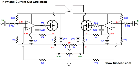
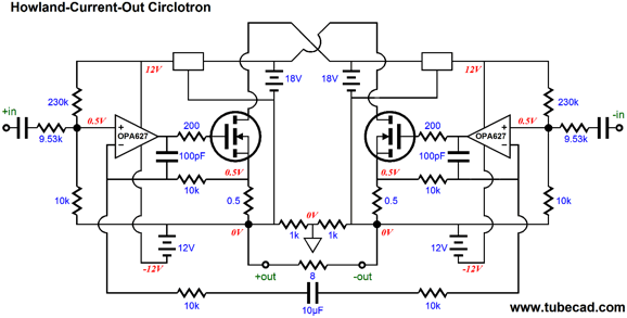
Let's begin with a solid-state version first, as it will require the least effort—well, at least conceptually. The following design uses two OpAmps, real OpAmps such as the nice-sounding OPA627, and two N-channel MOSFETs, such as the robust IRFP250.
Because this design just happens to be a class-A type—and, NO, not all Circlotrons must run in class-A; in fact, this one must be so because of the double use of the source resistors. We can enjoy the benefits of an auto-bias feature, wherein the OpAmp ensures that voltage drop across the 1-ohm source resistors sets both the idle current and half maximum output current swing. In this example, 1A of idle current and 2A of peak current output swing, which into an 8-ohm load equals 16W. If 0.5-ohm source resistors were used, we would see an idle current of 2A and a peak current output of 4A, which into an 8-ohm load equals 64W. Because the OpAmps establish a fixed and equal idle current for the MOSFETs, the DC offset is also eliminated by the OpAmps. The 360k resistor in parallel with the 10k resistor at the inputs equals roughly 9730 ohms, which the 9.76k resistor comes close to matching. If the 360k resistors were replaced by two 0.5mA constant-current sources, then the 9.76k resistors could be replaced by 10k resistors. (Mind you, the balanced signal source is likely to present some resistance, so the 9.76k resistors might still be a good idea.) Note how the two feedback loops, one positive and one negative, still obtain, with one terminating to the output and the other to the top of the 1-ohm source resistors. As I look at the circuit, I am troubled by the DC gain and by how common-mode signals, although invisible to the load, will nonetheless force the outputs to react. A better approach is to avoid the ground termination and use a capacitor between the two feedback resistors, as shown below.
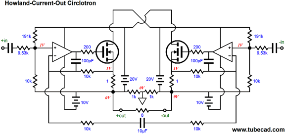
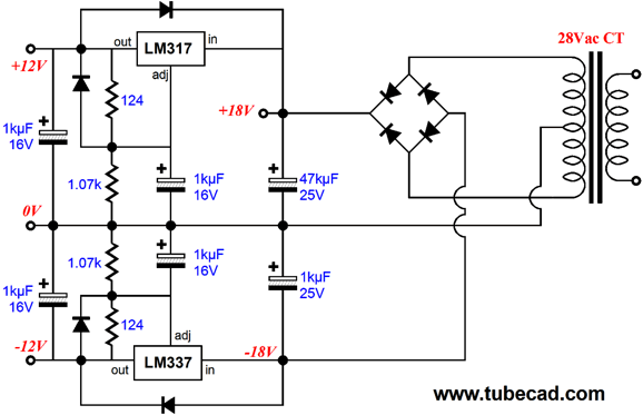
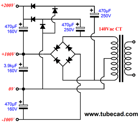
Note how the OpAmp sees dissimilar power-supply rail voltages, +20Vdc and -10Vdc. Why? Most OpAmps, such as the OPA627, can only withstand a power-supply differential voltage of 36Vdc and most OpAmps exhibit a dissimilar PSSR figure in relation to their power-supply connections, with the negative power-supply connection being far worse than the positive one. Thus, by using a negative-voltage regulator, such as the LM337, we can reduce the power-supply differential voltage to only 30Vdc and help overcome the OpAmp's asymmetrical PSSR. In other words, the OpAmp's positive rail voltage could be left unregulated, while its negative rail is regulated. Wow, just how many power transformers are required here? Yes, I know it is starting to sound too complicated, but just two center-tapped secondaries per channel are required, as the schematic below shows.
(Do not forget that the above circuit is only half of one channel's power supply.) Note how the OpAmp's rail voltages have changed to +12V and -12V, with the positive rail now also being regulated; further note how the MOSFET's rail voltage has been lowered to 18V. Why? As I was drawing the schematic, I had time to think about the circuit and I realized that although the typical power N-channel MOSFET, such as the IRFP250, requires a big turn-on voltage, but once fully turned on, it drops very little voltage from its drain to its source, so assuming source resistor values of 0.5-ohms, 18V should be enough to develop 16Vpk across an 8-ohm load. On the other hand, the OpAmp only needs to swing a relatively small window of output voltage; because its output DC couples with the MOSFET's gate and because its power supply voltages are not referenced to ground but to the Circlotron's nearest output, so the +/-12V rails are sufficient. In other words, had the two OpAmps shared a bipolar power supply that was "grounded," rather than two that are floating, then much bigger power-supply rails would be required, say +/-24V. Because this amplifier runs in strict class-A, as opposed to advertising "class-A," it idles at 1A per MOSFET, so a fairly beefy transformer is required. I would use at least a 60VA type, even though the output power is only 16W. In other words, four 28Vac-CT power transformers will be needed for a stereo amplifier (some transformers hold two center-tapped secondaries, so only one transformer would be needed per channel). So, now we have had time to digest the power supply, it is time to modify the amplifier's schematic, bringing it in accord with the new power supply. (The path the design of a linear electronic device takes is anything but linear. I know that my approach of creating as I go drives some readers crazy, as they are used to the prepackaged articles found in DIY magazines. On the other hand, the readers that I have met who like my indirect approach are just the type of imaginative and creative tube fanciers I like best.)
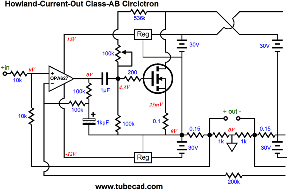
The 10µF is probably excessive, now that I look at it, as a 2µF capacitor would probably prove sufficient. What if you don't wish to run this Circlotron in strict class-A? A few changes will be required, such as the OpAmp can no longer control the MOSFET's idle current and more internal coupling capacitors will be needed. Something like the following.
The idle current and DC offset must now be set by hand, but the amplifier is no long restricted to class-A operation. Note how we lost both the input and the 10µF capacitors; also note how a single 200k resistor replaced the two 10k feedback resistors and how the MOSFET's rail voltage has been increased to 30V and the idle current reduced to about 300mA. We did, however, gain two internal coupling capacitors and a 100k resistor. The 100k resistor provides a DC voltage path for the OpAmp's inverting input. The big 1kµF capacitors are a kludge of sorts, whose need was discovered after several SPICE simulations revealed odd contortions in the output waveform with smaller-valued capacitors, such as 1µF. Because the amplifier is no longer restricted to class-A operation, one MOSFET will turn off, as the other fully engages. Great, more power, lower idle dissipation, party time. The problem is that the OpAmp expects its MOSFET to always be on, so it can complete its negative feedback loop through an active device and see its desired voltage relationships obtain. With the OpAmp's MOSFET turned off, the OpAmp loses its control over the output device and the OpAmp's output can swing wildly, as it seeks to regain control. It is as if by running the amplifier in class-AB we have broken our promise to the OpAmp, reneging on the implicit promise that its MOSFET would always be under its control. Well, the large-valued capacitor's huge time constant with the high-value negative feedback resistors, producing little phase shift, which seems to fool the OpAmp into believing that its MOSFET is still under its control. Ideally, this large-valued capacitor would not be needed; but then, ideally, the amplifier would be run in strict class-A, not class-AB. (To be frank, I am nervous about this result, which most SPICE simulations would not disclose, as they tend to be far too short in duration. I, on the other hand, like to run a special simulation wherein I let the circuit run for a long time and then only examine the last 2 milliseconds of results. This test often reveal problems that the short simulation runs can never show.)
Tube Current-Out Circlotron
Triode, transistor, and MOSFET—all used with one design. But before even thinking about a 60W, all-tube, current-out Circlotron, let's try designing a headphone amplifier version first. Baby steps, baby steps, as the late Dr. Gizmo used to repeat to me.
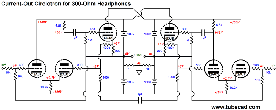
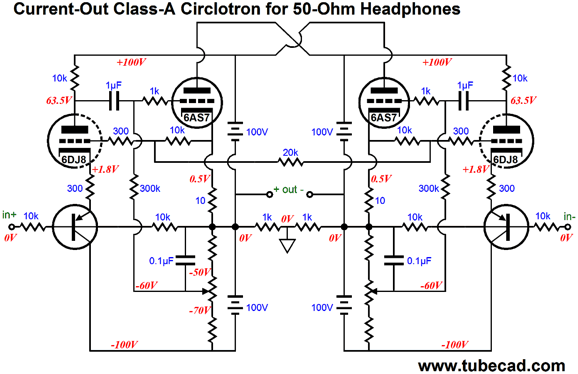
Current-Out Circlotron for Headphones
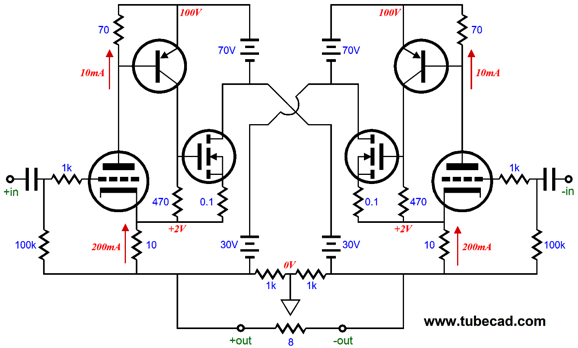
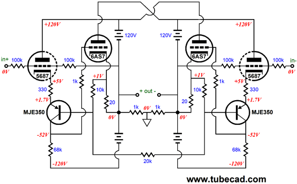
The differential driver stages function as OpAmps of sorts, with inverting and non-inverting inputs and some gain. The output triodes are cathode biased by the 200-ohm resistors. Their 2V cathode voltage is delivered to the driver stage via the 100k resistor. Normally such a DC offset voltage would be a pain and would require a coupling capacitor to avoid it. But in this design, it is a feature, as it overcomes the problem of dissimilar plate voltage in a cathode-coupled amplifier. Since a triode's mu is a measure of the relative effectiveness of the grid over the plate in controlling the current flow through the triode, the 2V of offset voltage can be countered by reducing the plate voltage by 2 x 17, with 17 being the 12AU7's mu, or 34V. In other words, with an idle current of 5mA per triode, and with a 6.8k plate resistor, the triode whose grid sees the 2V offset will also see its plate voltage reduced by 34V, which will allow it to still conduct the same amount of current as its brother. If a 6DJ8 had been used, the 2V would require a reduction in plate voltage of 66V, which is too much; thus, the use of the 12AU7. A 6SN7 or 6CG7 would require a drop of 40V. Give me half an hour and I will make this design much more complex, with regulated power supplies and constant-current sources. But all that is needed now is to understand how the circuit works, so we can move on to a bigger beast, one powerful enough to drive speakers. At second thought, maybe we should make another baby-step. If 32-ohm or 50-ohm headphones need to be driven, then a beefier output tube would be needed, say a 6H30 or ECC99 or 6AS7. In addition, a much higher idle current would be needed, say 40mA to 100mA. The following effort is also a Howland current-pump design, albeit with tubes and transistors, not an all-tube effort.
The PNP transistor forms an inverted cascode with the 5687 triode, but unlike a typical all-tube cascode, this cascode does not invert the phase. The idle current is set at 50mA per triode, so a peak output current swing of 100mA is possible, which implies a 5Vpk swing into a 50-ohm load. Dang, I like the look of this circuit, as it both elegant and bold, if I do say so myself. The only problem I can see is that although it would work just fine in SPICE simulations, it may not work in reality. Why not? The Circlotron circuit is a bit quirky at the best of times; it is like trying to stand upright while standing on each side of a well-greased teeter-totter (or seesaw or dandle board, depending where you live).
In other words, the DC-coupling throughout is quite desirable goal, but it also makes me nervous, as I can imagine the amplifier turning into a big flip-flop circuit. So, adding internal coupling capacitors would undo the auto-bias, but I bet it would also promote stability. Here is one possibility.
The PNP transistors (MJE350) work as emitter followers and provide no gain. The 6DJ8 delivers the gain that drive the 6AS7 output triodes. In spite of the fixed bias, this circuit must be run in class-A. Why? The key feature is that we are using the 10-ohm cathode resistors also as current sense resistors, thereby getting two functions from one resistor. But this cheat means that the voltage drop across the resistor must never equal zero, which it would when the amplifier left class-A operation and one output triode cut-off completely.
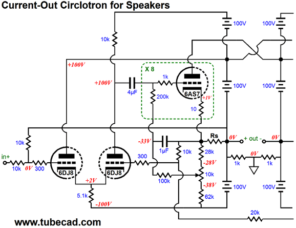
Current-Out Circlotron for Speakers The following design aims to put out about 36W into an 8-ohm load.
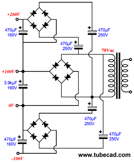
Where to start? Note 6DJ8 in place of the 12AU7; also note the 10mA of idle current that each 6DJ8 triode experiences. Also note no DC offset voltage is presented to the cathode-coupled driver stage, and that the power supply now holds a new power-supply +200V rail. The two feedback loops are in place. The assumption here is that sixteen 6AS7 triodes will be used per channel; in other words, eight 6AS7 tube envelopes per channel. (Were 120V B+ voltage used instead, then the power out would approach 60W, but the idle current would have to be lessened.) What would the power supply look like? Your only limitations are your ability to pay and your ability to lift heavy weight. Here is what I would do. Remember that each channel requires two of these circuits. Not shown is the heater power supply, which will be huge, as eight 6AS7 triodes draw 20A @ 6.3V. On the other hand, sixteen 6.3V heater elements placed in series would require 100V @ 2.5A.
Or something more conventional.
Mind you, this is still just a rough design concept, as the driver stage would be improved by the use of voltage and current regulation and, possibly, a different tube. But this circuit is a good starting point.
Next Time //JRB
|
I know that some readers wish to avoid Patreon, so here is a PayPal button instead. Thanks.
John Broskie
And
High-quality, double-sided, extra thick, 2-oz traces, plated-through holes, dual sets of resistor pads and pads for two coupling capacitors. Stereo and mono, octal and 9-pin printed circuit boards available.
Designed by John Broskie & Made in USA Aikido PCBs for as little as $24 http://glass-ware.stores.yahoo.net/
The Tube CAD Journal's first companion program, TCJ Filter Design lets you design a filter or crossover (passive, OpAmp or tube) without having to check out thick textbooks from the library and without having to breakout the scientific calculator. This program's goal is to provide a quick and easy display not only of the frequency response, but also of the resistor and capacitor values for a passive and active filters and crossovers. TCJ Filter Design is easy to use, but not lightweight, holding over 60 different filter topologies and up to four filter alignments: While the program's main concern is active filters, solid-state and tube, it also does passive filters. In fact, it can be used to calculate passive crossovers for use with speakers by entering 8 ohms as the terminating resistance. Click on the image below to see the full screen capture.
Tube crossovers are a major part of this program; both buffered and un-buffered tube based filters along with mono-polar and bipolar power supply topologies are covered. Available on a CD-ROM and a downloadable version (4 Megabytes). |
|||


| www.tubecad.com Copyright © 1999-2013 GlassWare All Rights Reserved |