| John Broskie's Guide to Tube Circuit Analysis & Design |
09 March 2014 The Return of the CCDA Octal
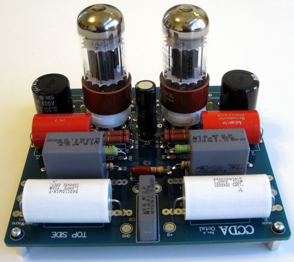
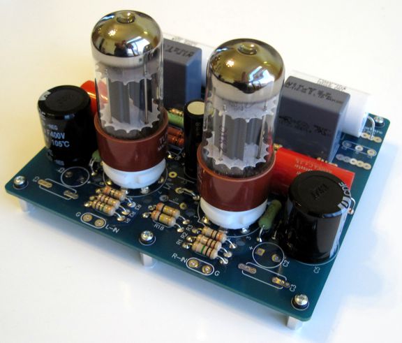
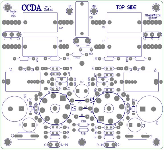
New CCDA Octal PCB
Since I have covered the circuit so many times before, I will let Mr. Google help find all the details. But blog number 235 and blog 161 might be good places to start. I am hooked on the positive feedback configuration, wherein the cathode-follower's cathode load resistor terminates into the cathode of the grounded-cathode amplifier. I have listened to both this setup and the setup that grounds the cathode follower's cathode resistor. I prefer the positive feedback configuration, as it seems to impart a slightly more jaunty, sprightly character to the sound, which CD playback particualarily welcomes; surely, welcome is anything that can help pry away from the music the CD's dead.
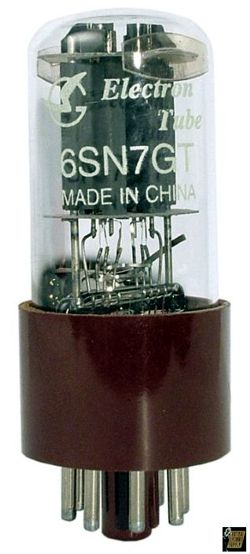
To test the PCB, I used the fine new Russian re-issue of the Tungsol 6SN7 tubes and a PS-1 regulated power supply that put out a regualted 275Vdc and 12V. The two 6SN7 heater were placed in series, which havle the current the heater regulator needed to deliver and gave it more DC headroom.
I almost built a 12SX7-based CCDA instead that would use a realively low B= voltage os only 100Vdc B+ voltage, but I want to hold on to the few remaining 12SX7 tubes that I own. Speaking of tube rolling, at half the price of the Russian re-issue of the Tungsol 6SN7 tubes, the Chinese brown-base 6SN7 tubes actually sound pretty good, which explains why you will find them in so many expensive retail tube equipment.
Whenever I switch out my Aikido line stage for a different topology, I miss the great PSRR that the Aikido displayed. But this time, with the PS-1 in place and the two large RC filters on CCDA PCB, I didn't hear any increase in power-suppy noise. I hate playing the audio reviewer, but the sound was very fine, particularly with the CDE capacitors selected.
The new CCDA Octal PCB and kit is available now at the GlassWare-Yahoo store. The PCB alone (with user guide) cost $30 USD. Wonderfully cheap, in other words.
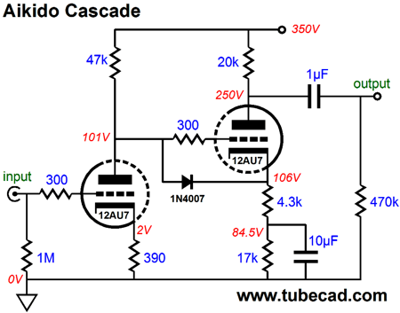
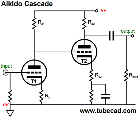
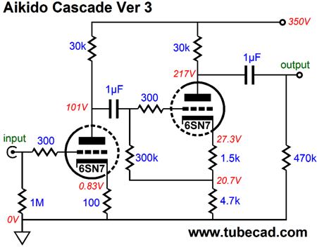
Aikido Cascade Here is how I put it back in blog number 83:
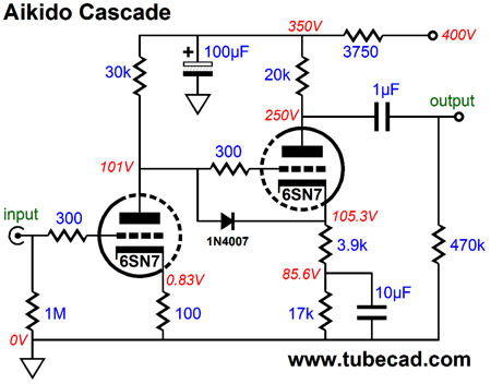
Well what sort of sonic gold am I about to place in front of your unsuspecting big toe? At first glance, you are likely to be dissipointed, as the Aikido Cascade looks just like the typical cascading of of two grounded-cathode amplifiers, with the added feature of DC coupling between stages, which is neither strikingly new nor uncommon. What is novel is the careful ratios between resistor values, which give rise to a surprising result: a stellar power-supply-rejection ratio.
The two cathode resistors for the output 12AU7 have been carefully chosen to create a null in the power-supply noise at the output. This explains the odd 4.3k cathode resistor on the second grounded-cathode amplifier, which seems out of place, as it appears to be neither essential nor effective. But this resistor makes all the difference, as it establishes the required gain from the second stage to amplify the first stage's leaked power-supply noise to just the right amount to cancel the power-supply noise at the second stage's plate. This magic is possible because the grounded-cathode amplifier inverts the input signal's phase at its output. The price we paid for the null in power-supply ripple escaping from the output was reduced gain and increased output impedance. In this example, with a 12AU7 tube, the gain could have been 176 without the 4.3k resistor; with it, the gain comes in at 44 (or about 33dB of gain). The output impedance is about 16k. Without the 4.3k resistor, the Zo would have been about 5.5k. If we added an additional RC filter to the first stage, however, we would undo the Aikido Cascade completely.
Although the second stage receives a fairly clean input signal, its connection to the dirty B+ results in a poor PSRR figure. (Of course, we could move the RC filter over to the right, so that both input and second stages received a cleaner B+ voltage.) So, how do we universalize this Aikido approach to the cascaded grounded-cathode amplifiers? The first step is to pull back and look at the AC relationships within the Aikido Cascade.
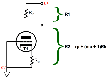
We start with the input tube, T1. This triode's plate resistor, rp, mu, and cathode resistor value all add up into a two-resistance voltage divider.
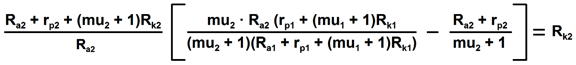
The formula for a two-resistance voltage divider is simple: ratio = R2/(R1 + R2). For example, say R1 equaled 9k and R2 equaled 1k, the ratio would equal 0.1; in other words, 10% of the B+ voltage would appear across resistance R2, as would 10% of the ripple riding on the B+ voltage. (If the cathode resistor, RK1, is bypassed by a large-valued capacitor, the formula no longer works for AC ripple, but it still works for DC voltage divisions.) The next step is to replace the tube variables into this simple formula: Ratio = [rp + (mu + 1)Rk] / [Ra + rp + (mu + 1)Rk]. Once we know the ratio (or percentage) of B+ ripple at the plate, we can determine the amount of gain the second stage must develop to counter the ripple at its output. For example, if 25% of the power-supply noise leaked to the first stage's plate, then the second stage would need to develop 1/0.25 amount of gain, or 4, to counter the B+ ripple, as -1 + 1 = 0. If the first stage handed off 33% of the B+ ripple, then the second stage would have to muster a gain of 3 to counter it. This is a beautiful image that the pond's surface reflects. Stare at it a bit longer and enjoy it, as I am about to toss a pebble into the pond. If the second stage uses a FET, MOSFET, or pentode, then the above picture remains true. But if a triode is used in the second grounded-cathode amplifier position, the math gets thicker, as 100% of the B+ ripple never appears at its output, as its rp and plate resistor also define a two-resistance voltage divider. For example, say that first stage leaked 25% of the B+ ripple and that the second stage leaked 50% of the B+ ripple, then the second stage would have to develop a gain of only 2 to counter the 50% of B+ ripple at its output, not the gain of 4 that the inverse of the first stage's ratio would seem to imply. Now, here is the problem, we can vary the second stage's cathode resistor, Rk2, to establish the required gain, but varying this resistor value will also vary the percentage of B+ ripple that appears at its output.
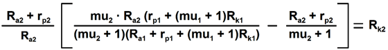
Here is the base formula, now solve for Rk2. (Note that Rk2 appears on both sides of the equal sign.) I have only had one cup of coffee, so I am not up to it. Instead, I would just ignore the effect that Rk2 has on the second stage's AC voltage division and use this formula:
This will get us close; then, we will have to experiment. (By the way, I have gotten a few indignant e-mails that go something like this: "I built your circuit, but I am getting 98V on the plate, not the 100V that your schematic shows. What the hell is going on here? What went so terribly, terribly wrong? Who can I sue?..." Stop and think about it: to be off by only 2% is a miracle. Anyone working with solid-state circuits, feedback-free circuits at that, who got within 2% of his target would be justly overjoyed.)
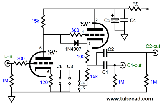
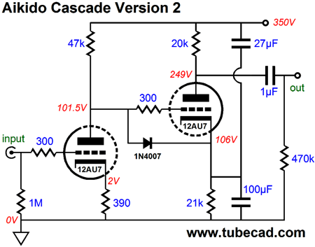
Aikido Cascade Version 2
In this variation, the two-capacitor voltage divider injects just the right amount of power-supply noise into the second stage's cathode to produce a null in power-supply noise leaving the output. Hallelujah: high gain and stellar PSRR. In addition, this variation offers a lower output impedance. Are we done now? Of course not. Yes, this variation yields a prodigious amount of gain; in this example, 176 (or about 45dB), but actually attaining the null in reality is a bit tougher, as the right value for the top capacitor may not be obtainable and some fiddling will be required in establishing its value. In general, it is always better to use resistors to establish critical ratios than capacitors, as resistors offer tighter tolerances and many more values—and are vastly cheaper. In both versions, the 1N4007 diode is a safety device that falls out of the circuit, once everything is hot and running, as the diode will become reversed biased, as the cathode will be much more positive than the grid on the output triode. But at startup, when all is cold, the diode will be forward biased and conduct, thereby preventing the second triode's grid from becoming 350V more positive than its cathode. Never a good idea.
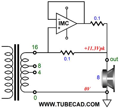
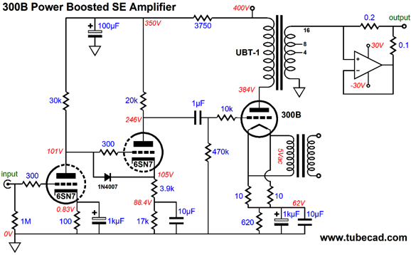
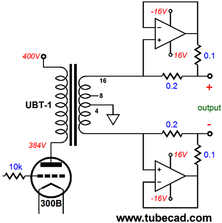
A Boosted 300B Single-Ended Power Amplifier Ideally, I would love to own a 300B-based single-ended amplifier that put out 36W. Since the maximum theoretical efficiency of a single-ended amplifier is 50%, which is never achieved in reality, such a desire can never be realized by a conventional single-ended amplifier and a single 300B. Fortunately, my imagination has never been bound by the conventional. Back in blog number 262, I showed how an impedance-multiplier circuit (IMC) could augment an existing conventional single-ended power amplifier. If the output transformer held a 16-ohm tap, then the following circuit could be used to double the amplifier's power output into an 8-ohm speaker.
As far as the existing single-ended power amplifier was concerned, it was driving a 16-ohm load, so it put out 11.3Vpk of voltage swing, which was needed to establish its maximum output of 4W into 16 ohms. The IMC then added the same amount of current that the single-ended power amplifier put out to the mix, so the speaker saw twice the power. Will this trick get us to 24W? It just might, but even 12W is a lot to ask from a single 300B, as something closer to 8W would be more within its comfort zone.
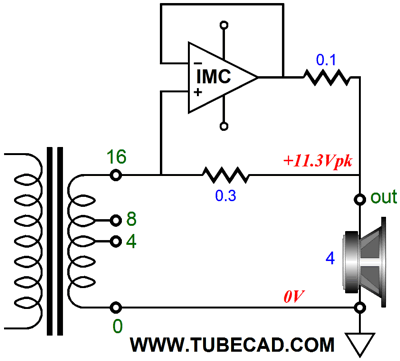
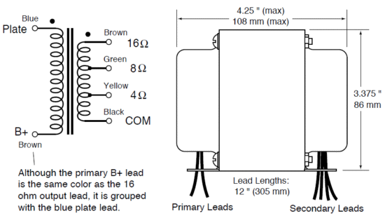
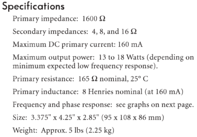
If we use a 4-ohm speaker instead, then we would get 16W into the speaker. This feat of electronic magic required that the IMC reflect to the output transformer a 16-ohm load, so the IMC's impedance ratio must equal 4:1, as 16 ohms divided by 4 ohms equals 4. The 0.1-ohm and 0.3-ohm resistors set this ratio in place. Since the voltage present at the IMC's output before the 0.1-ohm resistor and the voltage present at the 16-ohm transformer tap are the same, we can instantly see that the IMC must deliver three times the current that the transformer puts out. This fourfold increase in power is certainly impressive. But what can we do, if our speakers are the 8-ohm types, not 4-ohm loads? The best approach would be to design the single-ended power amplifier anew, with the augmentation of power from the IMC already in mind. An inspection of the 300B's plate curves and past practice shows that a plate load of between 1.6k to 5k seems to work best. In general, the 5k load-line is likely to give the least distortion and the least power output; the 1.6k load, the most distortion and power. The problem we face with a 5k primary is that the winding ratio must be high; in fact, the square-root of the impedance ratio equals the winding ratio. In this example, sqrt(5,000/16) = 17.7. So, what's the big deal here? The big deal is that if we plan on getting 36W into an 8-ohm load, the secondary must put out 24Vpk. Now, 24Vpk against a winding ratio of 17.7 equals a peak plate voltage swing of 425V! That is a lot of voltage swing. Far too much. What we need is an output transformer with a low-winding ratio. As I typed these words, I know that some will read low-power ratio. Do not make this mistake; the winding ratio is independent of the power output of a transformer. In fact, most big output transformers, the type that can put out 200W, hold low winding ratios. Unfortunately, single-ended output transformers that hold low winding ratios are hard to find. One exception is my old favorite, the One Electron UBT-1.
Its 1600-ohm primary impedance implies a winding ratio of 10:1 between the primary and the 16-ohm output tap (to the ground tap). Thus, if we can get the 300B to swing +/-240V swings at its plate, we can get +/-24Vpk swings at the 16-ohm tap and out of the IMC's output, which would yield 36W into 8 ohms. Now all we have to do is design the 300B output stage.
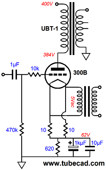
This is as simple as it gets. We could and probably should add some improvements, such as 5Vdc for the 300B heater, replacing the 620-ohm cathode resistor with a constant-current source, and my signature Aikido single-ended output stage PSRR enhancement, the capacitor from the cathode to the B+ in addition to the existing capacitors to ground. But let's keep it simple. The next step is to design a frontend. The obvious choice, based on what I have already written here, is the Aikido Cascade, except this time we will use a 6SN7-based design.
The B+ voltage of 400V is dropped to 350Vdc by the RC filter made up of the 3750-ohm resistor and the 100µF capacitor. The gain for this design is about 55, which comes close to what we need to drive the 300B to full power with an input signal of 1Vpk. If we desire a tad bit more gain, then the following version will deliver a gain of about 68.
(I prefer the first version, because I fear the cathode-resistor bypass capacitor on the first stage. But if you need the extra gain, then you need the extra gain.) Putting it all together, we get the following schematic.
Where to start? The IMC makes the 8-ohm speaker appear as a 24-ohm speaker to the UBT-1 output transformer's secondary, which in turn the primary reflects as a 2400-ohm load to the 300B's plate. The 300B's plate must swing 480V peak to peak to put out the +/-24Vpk at the output transformer's secondary's 16-ohm tap; thus, the 300B must idle at 100mA. This means that the 300B is putting out 12W and the IMC is adding 24W to make a total of 36W into the speaker.
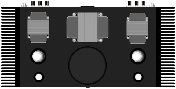
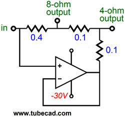
Now this is a hybrid that I would love own. Just imagine the chassis with its top panel holding two output transformers, one tube power transformer, two 300B and 6SN7 tubes, and a big potted toroidal power transformer, but with flanking heatsinks on the sides . More important, just imagine the sound of 36W seemingly coming from one 300B. In the drawing above, each channel gets three output posts. What is going on here? By just adding one more resistor to the IMC, we can get more universal use out of it, as it would then be able to drive to both 4-ohm and 8-ohm speakers.
Note how the impedance ratio is 1:3 for 8-ohm loads and 1:6 for 4-ohm loads.
By the way, 24Vpk into 4 ohms is 72W, not 36W. How many Magneplanar owners would love to hear 72W of 300B single-ended sound? Many, is my guess. I happen to love the sound from these big dipoles, but I know that my 10W single-ended amplifier is not up to driving them. Do not make the mistake of believing that only the 300B and the UBT-1 transformer or that only the Aikido Cascade frontend can be used. This is a universal topology, whose key elements are the output transformer and IMC. A 2A3 or 45 or 12B4 based single-ended amplifier could be power boosted, as could a 211 or 845 or 6C33 or El34 or KT88 or KT120. In fact, a push-pull amplifier based on any of these output tubes could be power boosted in the same fashion. The Aikido Cascade frontend could be replaced by an Aikido Cascode or just plain Aikido gain stage—or even the lowly SRPP. In fact, here is a third variation on the Aikido Cascade:
This time, the DC coupling, safety diode, and the large-valued cathode resistor bypass capacitor are jettisoned. Instead, we use a coupling capacitor between stages. The gain for the above circuit is about 55, so we haven't made any increase in voltage gain, but we have given the second triode much more voltage to play within, which we would need in this project, as 300B triodes require big grid-voltage swings. (The same gain as the earlier version, but with a different plate and cathode resistor values for the second stage, how is that possible? Since the first stage still holds the same values, it will pass the same amount of power-supply noise, so the second stage must deliver the same amount of gain to null the power-supply noise from the cascade's output.) Also note that the 4-ohm tap on the secondary falls at the 50% point of this winding. This means that the 4-ohm tap can be grounded and the "ground" tap will become an anti-phase output, so a balanced output can be used. This would allow us to halve the rail voltages that feed the IMC, but would require twice the IMCs.
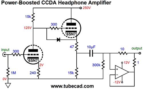
Or, we can go in the opposite direction and build a headphone amplifier based on this topology. For example, we could power boost a single-ended amplifier based on a 6H30 or 5687 triode, so that 50-ohm planer headphones could be driven hard.
Here we see a 6SN7-based CCDA headphone amplifier being power boosted by the IMC, which will make 300-ohm headphones appear as 3.3k-ohm loads to the 6SN7. The 10µF coupling capacitor is a bit small for 50- and 32-ohm loads, so 30µF might be the better choice.
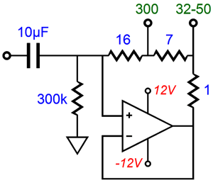
Of course, we could use the three-resistor IMC trick, so that the headphone amplifier would offer two output jacks, one for low-Z headphones and one for high-Z headphones, which would allows us to the use the same 10µF coupling capacitor for both types of headphones. The 300-ohm headphones would be multiplied by 3; the 32- and 50-ohm headphones, by 24.
Next Time
Since I am still getting e-mail asking how to buy these GlassWare software programs:
For those of you who still have old computers running Windows XP (32-bit) or any other Windows 32-bit OS, I have setup the download availability of my old old standards: Tube CAD, SE Amp CAD, and Audio Gadgets. The downloads are at the GlassWare-Yahoo store and the price is only $9.95 for each program. http://glass-ware.stores.yahoo.net/adsoffromgla.html So many have asked that I had to do it. WARNING: THESE THREE PROGRAMS WILL NOT RUN UNDER VISTA 64-Bit or WINDOWS 7 & 8 or any other 64-bit OS. One day, I do plan on remaking all of these programs into 64-bit versions, but it will be a huge ordeal, as programming requires vast chunks of noise-free time, something very rare with children running about. Ideally, I would love to come out with versions that run on iPads and Android-OS tablets.
//JRB |
I know that some readers wish to avoid Patreon, so here is a PayPal button instead. Thanks. John Broskie
Kit User Guide PDFs
And
High-quality, double-sided, extra thick, 2-oz traces, plated-through holes, dual sets of resistor pads and pads for two coupling capacitors. Stereo and mono, octal and 9-pin printed circuit boards available.
Designed by John Broskie & Made in USA Aikido PCBs for as little as $24 http://glass-ware.stores.yahoo.net/
The Tube CAD Journal's first companion program, TCJ Filter Design lets you design a filter or crossover (passive, OpAmp or tube) without having to check out thick textbooks from the library and without having to breakout the scientific calculator. This program's goal is to provide a quick and easy display not only of the frequency response, but also of the resistor and capacitor values for a passive and active filters and crossovers. TCJ Filter Design is easy to use, but not lightweight, holding over 60 different filter topologies and up to four filter alignments: While the program's main concern is active filters, solid-state and tube, it also does passive filters. In fact, it can be used to calculate passive crossovers for use with speakers by entering 8 ohms as the terminating resistance. Click on the image below to see the full screen capture.
Tube crossovers are a major part of this program; both buffered and un-buffered tube based filters along with mono-polar and bipolar power supply topologies are covered. Available on a CD-ROM and a downloadable version (4 Megabytes). |
||


| www.tubecad.com Copyright © 1999-2014 GlassWare All Rights Reserved |