| John Broskie's Guide to Tube Circuit Analysis & Design |
| 15 June 2014
User Guides for GlassWare Software
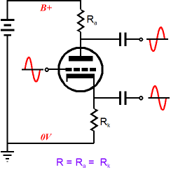
Phase Splitters (I have seen beautifully constructed, very expensive tube-filled power amplifiers perform terribly due to a misapplied phase splitter. In one case, I was asked to offer a solution by the amplifier's designer. The phase splitter held the wrong tube and got too little voltage, so the phase splitter clipped before the output stage did, reducing the potential output power by half: a fairly easy fix in other words. Oddly enough, he just could not wrap his head around how the phase splitter was at fault; but, then, he really didn't understand how it functioned internally. He wasn't a fool; indeed, Mensa would have gladly accepted his membership application. For him this was blind-spot, an intellectual black-hole that could neither be glimpsed directly nor examined indirectly by intellectual inspection. We all have our blind-spots; most prefer to look away, while a few prefer to peer into the darkness. But be warned, as Nietzsche pointed out, "And if you gaze for long into an abyss, the abyss also gazes into you.") The simplest phase splitter is the split-load phase splitter, whose construction needs only one triode and two equal-valued resistors.
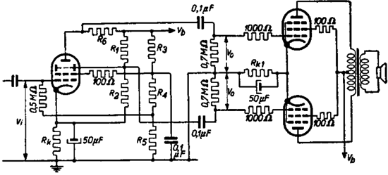
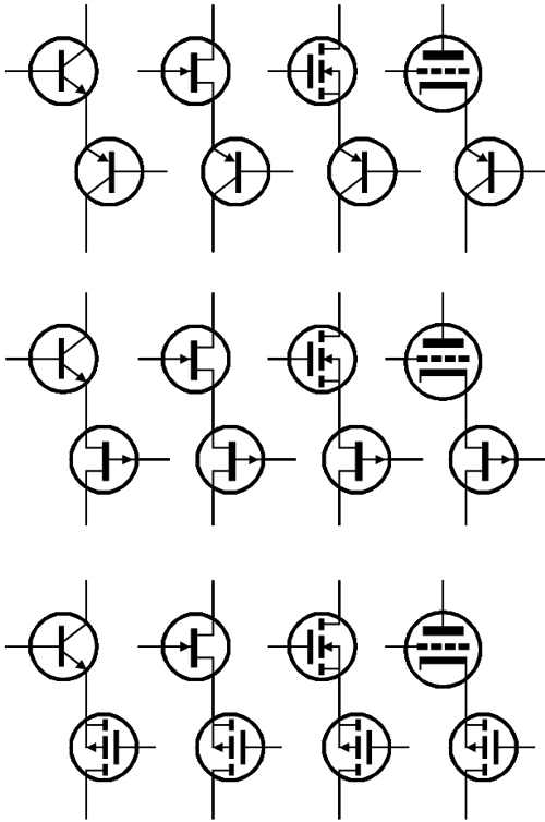
In spite of or, perhaps, because of its simplicity, this phase splitter works fantastically well, as long as you fully understand how it is to be used. On the other hand, if complexity is your goal, then truly complex phase splitters might be devised. For example, many FETs, transistors, MOSFETs, and OpAmps could be used—or a single secondary-emission tetrode, the Philips EEP1, as shown below.
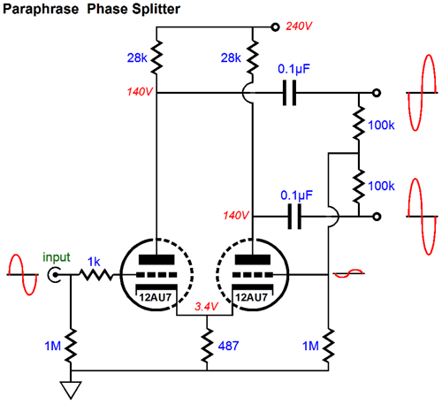
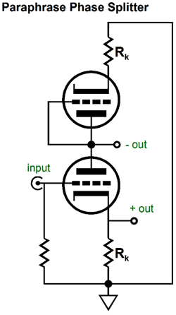
In general, complexity is a bad idea in a phase splitter. Why? The phase splitter is usually situated within a more complex power amplifier, which most often uses a global negative feedback loop, which in turn means that stability must be maintained, lest the amplifier transform into a power oscillator. Thus, the goal is to create simple, effective phase splitters. Some examples are the paraphrase phase splitter and the long-tail phase splitter. The paraphrase phase splitter uses its own negative feedback loop to establish its inverted output, which should make us a tad nervous when using this phase splitter within a feedback-laden power amplifier.
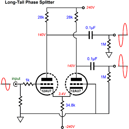
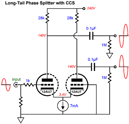
The long-tail phase splitter forgoes the negative feedback loop and uses a large-valued, common-cathode resistor to establish its two phases of output signal.
Because the common-cathode resistor is so large in value, invariably a negative power-supply rail is required. The larger the common-cathode resistor's value, the better this phase splitter works. Thus, it is an easiest step to move to this resistor with a constant-current source, which often allows us to lose the negative rail.
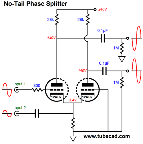
But even with the constant-current source, this phase splitter does not deliver equal output signal amplitudes. The workaround is to use different values for the plate resistors, making the one on the left slightly smaller than the one on the right. Now fasten your mental seatbelts, as we are about to fly into unmapped territory. We could replace the constant-current source with a common cathode resistor and use a coupling capacitor to attach to another input signal, with the same phase, but half the amplitude.
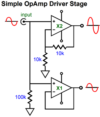
With the coupled cathodes receiving an input signal equal to half the signal that the left triode's grid sees, the right triode effectively sees an inverted input signal. And, effectively, both triodes see the same signal amplitude, as the left triode's cathode sees half the signal that its grid sees, making the total cathode-to-grid voltage swing equal half of the signal presented to the grid. Well, just where do we get a pair of same-phase input signal that differ in amplitude by two to one? An input signal transformer could be used, if it held a center-tap on its secondary. Or, we could use a simple OpAmp circuit, such as the one shown below.
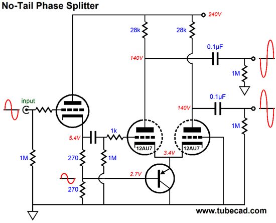
The top OpAmp produces a gain of two, while the bottom OpAmp is configured as a unity-gain follower. Or, we could use the following input stage to drive the phase splitter.
The cathode follower delivers 100% of its output to the left triode's grid and 50% of its output to the PNP transistor's base, whose emitter, in turn, drive the common cathodes. (With a negative power-supply rail and the replacement of the PNP transistor by a P-channel FET, we could lose the cathode follower input stage.)
Bastode Phase Splitters
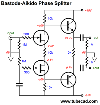
This time, the bastode appears in a phase splitter. We start with N- and P-channel FETs in a bastode configuration. The top FET receives the input signal and the bottom FET is presented all of the negative power-supply-rail noise, which we assume is identical to the positive power-supply-rail noise, same in magnitude, but differing in phase.
The 10k source resistor, the one that sits between the the two FETs, sees both the input signal and the negative power-supply-rail noise imposed across its leads, which develops a corresponding AC variation in current flow, which then flows through both 10k drain resistors. The input signal gets inverted at the top 10k resistor's connection tot he NPN transistor's base, while the bottom 10k resistor presents an in-phase signal tot he PNP transistor's base. Thus, we have our two phases of output signals.
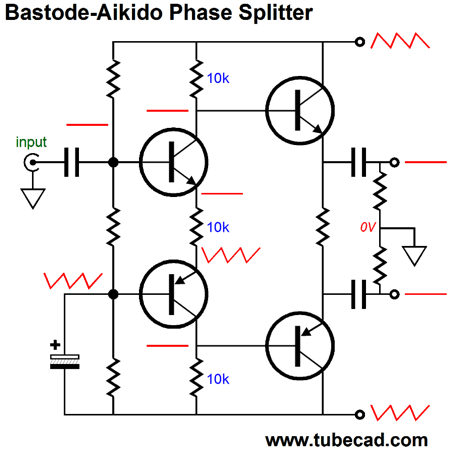
The above variation uses only transistors, but the same mode of operation results. The word "Aikido" enters the name, as the current variation created by negative power-supply-rail noise ends up canceling the noise at the two outputs.
The input capacitor was needed to allow greater output voltage swings. On the other hand, if bigger power-supply-rail voltages are used, then we can lose the coupling capacitor.
Note that the electrolytic capacitor no longer terminates into the negative power-supply rail; instead, it terminates into ground. Why? This variation comes pre-Aikido-ized, as the PSRR is already exemplary. Okay, I better stop here, or I will end up drawing another ten bastode schematics.
Metaphrase Phase Splitter
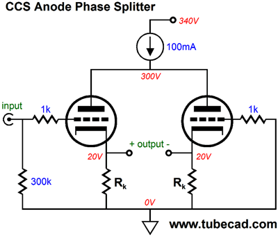
If the above circuit seems familiar, it's probably because you saw it before in blog number 191. I referred to the circuit as the "plate-driven phase splitter." Perhaps, "anode phase splitter" would be a better name.
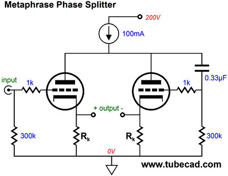
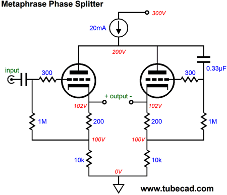
Okay, now that you have returned from rereading that post, I will offer only a quick recap on how it works. The constant-current source sets a fixed current flow and resents a near infinite output impedance. The two triodes find only one current path to the B+ voltage, which is through this constant-current source. If one triode conducts more current, the other must conduct less current by an equal amount. Say, in this example, that the left triode sees a positive input voltage and its conduction increases from 50mA to 70mA, then the right triode's conduction must fall to 30mA, as the total current draw must equal 100mA. How is this brought about? If you do the math, you discover that plate voltage must vary by the input voltage against the triode's amplification factor (mu or µ) divided by two. For example, if the mu is 10 and the input voltage is 1V, the plate voltage will drop by 5V. And as a triode's plate is 1/mu times as effective as its grid in control current flow through the triode, the right triode's conduction will fall by the same amount as at the left triode's conduction increases. Now, we are going to supercharge this topology, thereby creating a new phase splitter, the Metaphrase Phase Splitter. No, that was not a typo, as metaphase was already taken by biologists (for naming the stage of mitosis and meiosis, following prophase but preceding anaphase, during which the chromosomes are aligned along the metaphase plate, as everyone knows ;). "Metaphrase" comes from the Latin translation (metaphrasis) of the Greek word, which means a word-for-word translation. In contrast, "paraphrase" means a restatement in different words, usually with the aim of increasing clarity—clarifying meaning, in other words, by using other words.
Note how both grids now see an input signal; the left triode gets the input signal, while the right triode gets its input signal from the common plates. What does this buy us? The answer is some truly interesting performance. Here is an example; the plate no longer swings by the input signal against -mu/2, instead, it swings something closer to -Vsig•mu/(mu + 1), which means that the constant-current source no longer needs to displace as much voltage. If we think about the circuit only in terms of AC signals, not DC relationships, then the following schematic will not appear so insane.
Where's the constant-current source? In AC terms, it falls out of the equation, as it represented an infinite impedance. If we treat the above circuit as being an example of a grounded-cathode amplifier, then the AC gain at the connection between the two plates would equal: Gain = (muRk + rp) / [(mu + 2)Rk + rp(1/mu + 1)] In terms of output impedance, the results are also quite interesting, as the performance is identical (well, nearly) to what a split-load phase splitter delivers.
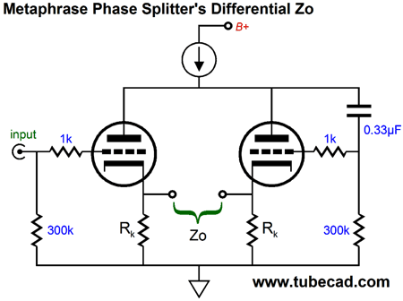
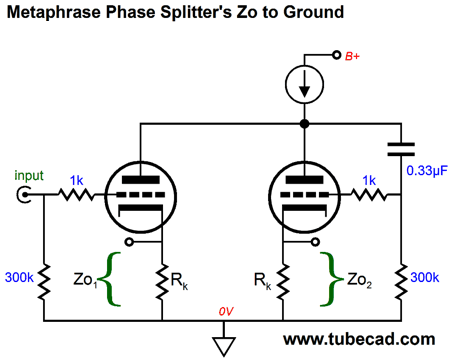
The two cathode resistors, Rk, are effectively in series with each other and both cathodes present low output impedances, with the left cathode being a tad lower in impedance. Zo = 2Rk || [rp/(mu + 1) + rp/mu] where || means in parallel with, such that X || Y is the same as XY/(X + Y). Thus, the differential Zo is very low indeed. Low enough to drive low-impedance headphones, say 250-ohm to 600-ohm types. But the impedances relative to ground, however, present a quite different story. Much like the split-load phase splitter, each output presents a wildly different output impedance relative to ground. And much like the split-load phase splitter, the dissimilar output impedances are usually not a big deal—unless, we foolishly somehow make them so, for example by loading the two outputs with dissimilar load resistances or load capacitances. If both loads are identical, however, as they usually are in a push-pull amplifier, then we needn't worry much if at all. Where we must worry is when we use this phase splitter in a unbalanced fashion, say in phase selection setup, wherein only one output is engaged at a time.
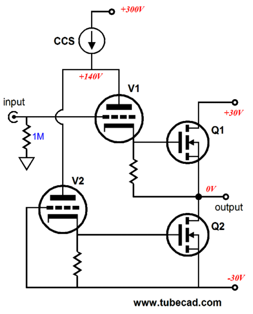
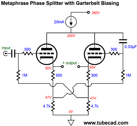
The non-inverting output impedance, the one on the left, Zo1, is low; its brother, the one on the right, Zo2, is high. The exact values are: Zo1 = Rk || [(rp + rp/mu + Rk) / (mu + 1)] and Zo2 = Rk || [(rp + rp/mu +(mu + 1) Rk] Actually using the metaphrase phase splitter in most power amplifiers usually requires a second set of cathode resistors, as shown below. Alternatively, if a fixed-bias-voltage is used, then we can get away with two cathode resistors.
As I look at this schematic, I see a potential problem, depending on how big a voltage swing is needed from the phase splitter. Do not forget that the plate will swing a slightly larger voltage than the input signal, which means as the left triode's cathode swings up 40V, the plate voltage will drop by about 41V, leaving only 17V for the triode. The workaround is to give the triodes more cathode-to-plate voltage to begin with. Of course, as nothing is gotten for free, we will have to pay with slightly increased distortion. Another small problem we may face is getting both triodes to draw an equal idle current. One workaround is to use the garter-belt biasing technique, wherein one triode sets the idle current for the other, which averages out the differences. This works amazingly well, which using dissimilar triodes reveals.
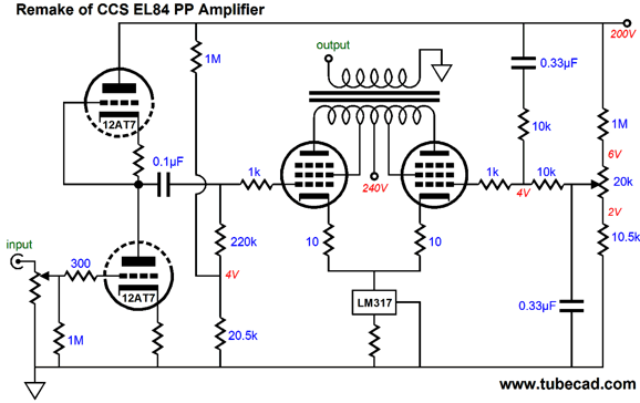
Okay, now let's move on by returning to my last post, blog number 293, wherein we looked into Bruce Heran's long-tailed, push-pull EL84 power amplifier. Bruce's design used a constant-current source to split the phase for the pair of push-pull output tubes, so an unbalanced input signal could be used. I pointed that the problem with this approach was that as the output stage didn't receive a balanced input signal, its CMRR was very poor, as it would treat power-supply noise superimposed upon the input signal as just more signal to be amplified, not ignored. An additional problem, which I didn't mention in that post, is that the constant-current source displays a lower voltage limit, below which it ceases to work well as a constant-current source. Remember the constant-current source was made up from an LM317 and a series resistor, both of which must displace some voltage to function: exactly 1.25V for the resistor and about 2.5V for the LM317. Well, here is how we can improve the CMRR (PSRR) and get bigger output swings from the output stage and establish idle-current balance between the output tubes.
Note how we have given the LM317 a lower floor of 4V within to operate. Also note how the potentiometer no longer must pass heavy current. And, last, note how the right output tube's grid sees the same 50% of the power-supply noise that the left output tube sees at its grid, which allows the output stage to exercise its excellent CMRR upon this common-mode noise. Okay, now lets move on to something quite a bit more interesting. Now ask yourself how we could create a cathode-follower-based output stage that used an unbalanced input signal. Would that even be possible? And if it were possible, what would the benefits be and what new liabilities would ensue? We all know that the benefits are both lower distortion and output impedance, as a cathode follower employs 100% degenerative negative feedback to keep its output inline with its grid. The new liability would be the required huge input signal needed to drive the output stage to full output.
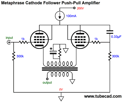
Unbalanced Push-Pull Cathode-Follower Power Amplifier The trick is to use the metaphrase-phase-splitter topology, so the right output tube gets its required input signal.
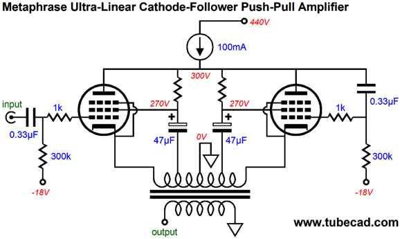
As the left output tube sees a positive input signal, the right tube sees a negative input signal, one slightly greater than its cathode voltage swing. Conversely, a negative input signal prompts a positive input signal for the right tube's grid. Since the transformer's primary bridges the two cathodes, the output impedance will be very low indeed. For example, if the primary reflects an 8k-ohm impedance, the differential output impedance of the metaphrase output stage will be reduced by a thousand-fold. In other words, the DCR of the secondary might prove greater than the output stage's output impedance. The constant-current source shields the output stage from the power-supply noise at the B+ connection, greatly enhancing its PSRR. On the other hand, the output stage still displays the problem of not rejecting the power-supply noise riding atop the input signal. The only workaround here is to make sure that you provide a clean input signal. Note how a shared bypassed cathode resistor is used to set the bias. Well, actually the constant-current source set the idle current by moving the plate voltage up or down as needed to establish the desired idle current. What about replacing the cathode resistor with another constant-current source? No, no, no. Never place two constant-current source in series, as the voltage division seldom—if ever—divides as you would expect. What about ultra-linear operation of the output tubes, is that possible? Yes, indeed. The ultra-linear taps are connected to large-valued capacitors that relay the ultra-linear signal to the screen grids.
Note how this variation uses fixed bias. The primary's DCR can be used to measure the current flow through each output tube.
Next Time
For those of you who still have old computers running Windows XP (32-bit) or any other Windows 32-bit OS, I have setup the download availability of my old old standards: Tube CAD, SE Amp CAD, and Audio Gadgets. The downloads are at the GlassWare-Yahoo store and the price is only $9.95 for each program. http://glass-ware.stores.yahoo.net/adsoffromgla.html So many have asked that I had to do it. WARNING: THESE THREE PROGRAMS WILL NOT RUN UNDER VISTA 64-Bit or WINDOWS 7 & 8 or any other 64-bit OS. I do plan on remaking all of these programs into 64-bit versions, but it will be a huge ordeal, as programming requires vast chunks of noise-free time, something very rare with children running about. Ideally, I would love to come out with versions that run on iPads and Android-OS tablets.
//JRB |
I know that some readers wish to avoid Patreon, so here is a PayPal button instead. Thanks. John Broskie
Kit User Guide PDFs
E-mail from GlassWare Customers
High-quality, double-sided, extra thick, 2-oz traces, plated-through holes, dual sets of resistor pads and pads for two coupling capacitors. Stereo and mono, octal and 9-pin printed circuit boards available.  Aikido PCBs for as little as $24 http://glass-ware.stores.yahoo.net/
Support the Tube CAD Journal & get an extremely powerful push-pull tube-amplifier simulator for TCJ Push-Pull Calculator
TCJ PPC Version 2 Improvements Rebuilt simulation engine *User definable
Download or CD ROM For more information, please visit our Web site : To purchase, please visit our Yahoo Store: |
|||


| www.tubecad.com Copyright © 1999-2014 GlassWare All Rights Reserved |