| John Broskie's Guide to Tube Circuit Analysis & Design |
| 21 July 2014 
Blog Number 300! Beyond the issue of my potential longevity, is the prospect of an additional 700 posts really likely? In other words, could there really be 700 potential new blog posts? Is that number possible? Probably not, but then so, too, was 300 possible new blog posts 12 years ago. Many would, indeed did, tell me, that all that could be done with tubes had been done with tubes—long before I was born. I disagreed then, and still do. Back in post number 278, I wrote the following:
Well, each new post strives to prove this contention.
Making Snazzy Schematics Although I have wanted to do so for many years, apprehension, plain fear, and the dread of perceived potential doom—all have contributed to my reluctance, my unwillingness to write on this topic. In short, Judge Not Lest Ye Be Judged! What a valiant display of courage is the writing a book on grammar or on manners or on etiquette—or any book that outlines the socially correct way of acting. I remember reading hostile reviews of John Simon's excellent 1980's book, Paradigms Lost: Reflections on Literacy and Its Decline. These scornful reviews all took the same form:
Worse still, Simon was (and still is) a critic, a literary, theater, and film critic, not an English or rhetoric professor. And his sharp and masterful writing style made his jabs and jeering remarks all the more trenchant and, thus, all the more memorable. Here was a man, whose job was to judge other's artistic efforts and who spoke English—along with French, German, Hungarian, and Latin—as a second language, judging and condemning America's declining literacy. The nerve!
Well, the drawing of schematics is also a social activity. Although no stern grammarian, a ready wooden ruler in hand, will disapprovingly look over your shoulder, your efforts will be nonetheless judged, so many of the overriding rules of social conduct apply, such as attention and consideration. Just as a map of Paris is not Paris, a schematic of a circuit is not the circuit. It is an idealized visual representation of the circuit. If drawn well, a schematic allows others to clearly and quickly see the circuit's topology: its arrangement of parts and their interconnections. If drawn poorly, the schematic presents an irritating puzzle, an irksome brainteaser, a needless chore. If drawing schematics is part of your job, then your boss and customers will judge your schematics—and, by extension, you. A sloppy or ill-conceived schematic reveals more than you might wish.
If you are asking others for (free) help, delivering a messed-up schematic is an insult, as it boldly says that the receiver is not worth the extra effort. If you must submit an ugly schematic, say you are eight years old or nearly blind or suffer from the shakes or are bedridden, then at least apologize for its ugliness, thereby acknowledging your regret for the extra effort needed to decipher the unsatisfactory schematic. The only thing worse than a badly-drawn schematic is no schematic. I wish I had a dollar for every time that I have received an e-mail that held no schematic and yet asked some question about the invisible circuit, as I would love to buy some fancy planar headphones. Many begin thus: "In your recent post your circuit is interesting, but I don't understand why..." Well, have you ever known me to post only one circuit, only one schematic? What I want to know is why he couldn't just copy and paste the schematic in his e-mail to me; was that really too much to ask?
Schematic Rules Speaking of rules, a good first rule might be that a schematic must be drawn as an abstraction, not as a map of the actual physical circuit layout. What does that mean?
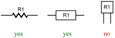
It means that you do not layout the schematic to show how you ended up actually laying out your physical circuit. It means that we use schematic symbols, not little pictures of batteries, capacitors, inductors, resistors, solid-state devices, transformers, and vacuum tubes. It also means that the symbol size does not reflect the electronic part size or value; for example, a KT88 tube is much bigger than an EL84, but use the same sized pentode symbol. It means that the symbols must be the same as everyone else uses. Of course, in Europe, you will draw a rectangle for a resistor, whereas here in the States we use the saw-tooth symbol. This means that although you only use bulk-foil resistors in your electronic project, you cannot use squares for resistors.
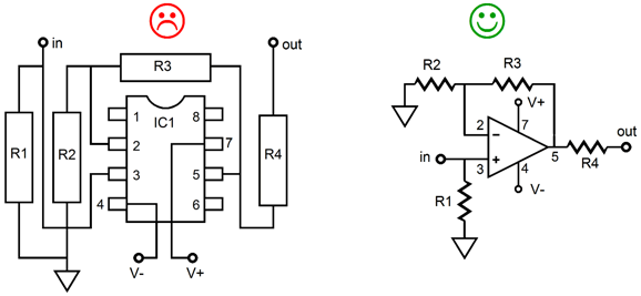
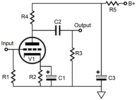
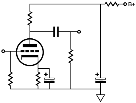
It also means that you should stick to accepted display of generic circuits, just as all stop signs must abide by the same shape. Here is an example: what do you think of this radically new topology shown below?
Obviously, so great a departure from common circuit practice should be rewarded with a new patent, no? If stuffed into a glamorous enclosure, fitted out with a fancy remote control, using a rare, odd NOS tube, such as the 2C43 transmitter tube, such circuit would be a bargain at $12,000. Perhaps you are still reeling from the striking novelty of the design, so much so that you are not convinced that this new circuit would, in fact, work. Rest assured it does. Now let's redraw the circuit in accordance with established custom.
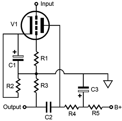
Most importantly, this means that the schematic should show the circuit's topology, not its actual physical layout. For example, new PCB advances now allow resistors to be imbedded within the board's layers, so soon you might see PCBs that seemingly hold no resistors. But the resistors are still part of the circuit and must be shown in the schematic. Laying out a good schematic is not the same procedure as laying out a good PCB. A second rule worth following is that the schematic's orientation should prove informative. For example, just as we read from left to right (sorry Israel), schematics should flow from left to right, with the input at the left and the output at the right. Take any common circuit and horizontally flip its schematic layout and behold how strange it looks. Yet, every technical aspect is correct. For example, what is the name of the following circuit?
I must admit that I have broken this rule when I draw power supplies, as I often placed the power transformer at the right and the power supply's output at the left. (I have gotten many angry e-mails over this failing of mine. At the time, I thought such complaints were ridiculously picayune; no longer, as I now realize that I had placed needless roadblocks to understanding.) How did I pick up this bad habit? I am sure it began when I would draw an entire amplifier in one long horizontal schematic, with the input at the left, the output in the middle, and the power supply at the right.
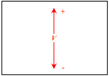
In addition, a schematic's orientation should place an implicit voltage gradient, with positive voltages at the top and negative voltages at the bottom. This is not an absolute rule—few rules are—but one worth conforming to, as the expectation is that the B+ appears at the top and negative voltage appear below ground.
I vividly remember my frustration at reading schematics of early transistor designs. In the first days of transistors, useable NPN type transistors were rare, so most transistor circuits exclusively used PNP types; but the schematics placed the negative power supply at the top of ground.
These upside-down schematics made the transistor circuits seem more alien than they actually were. The third rule is that schematic should display an even proportion or symbol density throughout. In other words, part symbols should not tightly cluster in one corner and then sparsely populate the rest of the schematic.
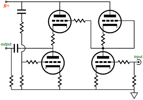
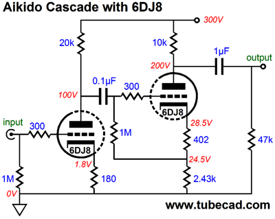
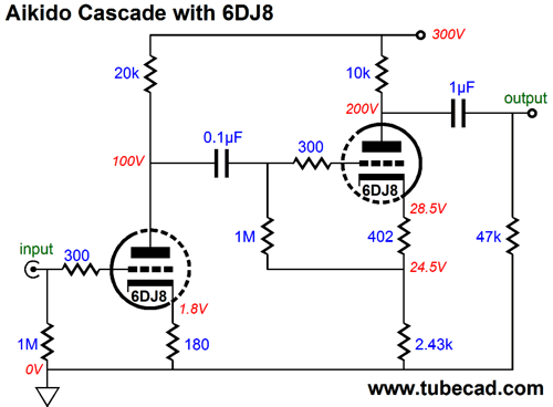
A few weeks ago, I received an e-mail from a very bright reader, who was kind enough to include my own schematic of the Aikido Cascade with a 6DJ8 tubes as shown above. As I looked at the drawing, I was embarrassed. Had I really drawn that schematic? It was too tight, too claustrophobic. The circuit was simple, yet the tight schematic seemed to imply a false complexity. Here is what I should have drawn.
Maybe a tad bit too roomy, but certainly an improvement. (One problem—or blessing—I face is that I have only 580 pixel width to fit my schematics in this blog. With today's bigger monitors, I must rethink that limitation.) Do not forget that the aim here is not for the scale, but an even proportion, an even distribution of symbols. Indeed, it was a great development when maps of subway or train routes were redrawn, not to scale, but to an even proportion, making them easier to understand. For example, an industrious fellow actually redrew the map of the Washington Metropolitan Area Transit Authority (WMATA) subway system, a geographically accurate version of the Metro map. Here is a review of his effort:
A fourth rule is that parts should bear a label or a value or both.
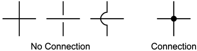
I often receive schematics that hold neither and I am then asked: "What should the value of the resistor be?" Which resistor? And what are the values of all the other resistors and what is the B+ voltage? Who knows? I certainly don't. The fifth rule is that the schematic must make clear which wires overlap and which connect. Usually, a dot is used to mark a connection. As long as the dot is bold enough, this works well. But small dots are often lost in photocopying or computer image resampling. I use 180-degree arcs to denote a wire crossing over another wire and not connecting, but the convention is either to use no dot or to show two little gaps.
The sixth rule is not essential, but makes the biggest difference in perceived schematic competence: consistent alignment. We prefer looking at a schematic that seems to obey an invisible, but consistent grid. Prefer? Who says we prefer anything? What makes a woman or a man's face attractive? Clear skin helps, but the non sine qua (something absolutely indispensable) of attractiveness is symmetry. Want to make your face shot instantly more attractive? It's easy: just throw away half of your face, either the left half or the right half, then use Photoshop to fold the remaining half over as a mirror image, thereby making your face perfectly symmetrical. I applied this trick to the picture of an already beautiful face, and here is the result. The stuff that dreams and advertising campaigns are made of.
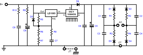
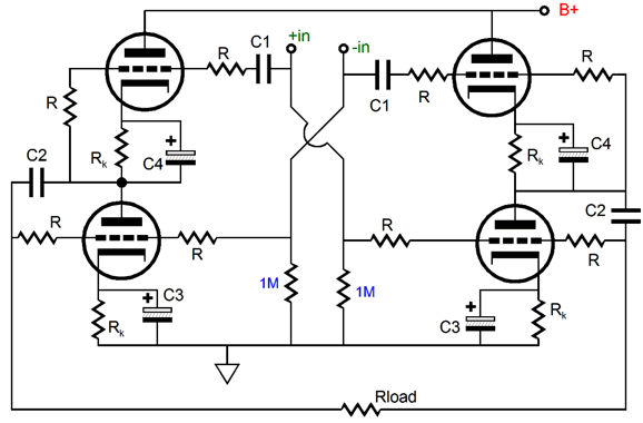
Symmetry pleases. Infants much prefer to look at images of perfectly symmetrical faces, so our preference is inborn. Female butterflies and birds judge potential suitors by how symmetrical the patterns on their wings appear. Why? Symmetry vouchsafes genetic integrity, which furthers the likelihood of your offspring surviving in this harsh world. "Symmetry," as Blaise Pascal told us, "is what we see at a glance." And it was Pascal's fellow Frenchman, Henri Poincare, who put it so beautifully: "It is the harmony of the diverse parts, their symmetry, their happy balance; in a word it is all that introduces order, all that gives unity, that permits us to see clearly and to comprehend at once both the ensemble and the details." Here is an example of missing schematic symmetry: a Broskie cathode follower setup as a balanced-input, balanced-output headphone driver stage. (A very good idea, by the way. I would, however, lose the electrolytic capacitors and maybe try diodes in place of the Rk resistors.)
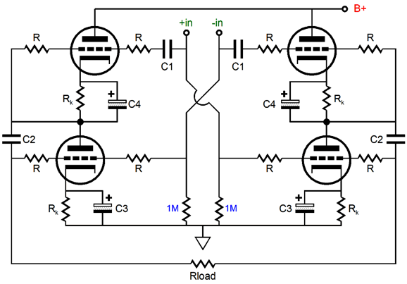
Everything is correctly connected, so the schematic is technically perfect. Still, it is an eyesore. (I get seasick from staring at it.) Here is the aligned version.
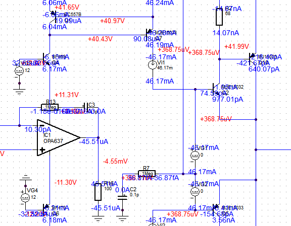
Which looks more professional? Which is easier to understand? Note that forcing alignment took only an extra minute or so. The seventh rule is take advantage of color. The year is 2014, not 1984. Color printers are cheap and readily available; and all computer displays are in gorgeous color these days. Even a black-and-white laser printer can reveal color, as most can render gray. (In fact, even if the printer only prints in absolute black and white, there is an implicit color in the density of black objects upon the page.) I like to use the color red for voltages, blue for part values, black for part designators, and green for things like inputs and outputs. As a quick aside, please do not go too crazy with fonts (typefaces for those in the know). Just because your computer comes with 500 different fonts does not mean that you must use them all. What about rules eight, nine and ten? Who says that there must always be ten rules, other than God that is? If you must have an eighth, ninth, and tenth rule let them be clarity, clarity, clarity. D'abord la clarté,” Anatole France wrote,“puis encore la clarté, et enfin la clarté”—clarity first, last, and always.
Breaking the Rules She pointed out that the greatest feature of computer-rendered architectural drawings was that they were consistent, which was also their greatest failing, being consistently flat in an artistic, emotional sense. She then pulled out a hand-drawn architectural drawing and told me what she read in the varying lines and changing drawing styles: that the architect was knowingly creating blight, which his hand-drawn lines revealed. He had been paid to create generic apartments that would be as ugly as any designed by the Soviet Housing Authority. Square and featureless buildings that oppress the soul and gave arsonists a good name. Yet, there was, hidden within his drawing, hope. He had drawn the windows with an obvious loving care, which she took to mean that while he acknowledged the brutal ugliness of his effort, he claimed that this structure could be, although probably wouldn't be, redeemed, if the windows were made sufficiently attractive, as they would counter the hulking bald dreadfulness of the design. She pointed out how, in the alternative computer-rendered architectural drawing, that frail hope would be lost. Well, in drawing schematics, we must on occasion break a rule. Here is an example: the first rule was that a schematic must be drawn as an abstraction, not as a map of the actual physical circuit layout. But often we want to impart the importance of actual part placement, for example, grid-stopper resistors must actually be soldered as close the grid as possible, if they are going to do their job, just as critical bypass capacitors must be placed right next to the part they bypass. This is vital information and I am willing to break the rule in order to convey the information. Note, however, that my breaking a rule only stands out because I didn't break all the rules all the time. Those who always yell are soon ignored. The good poet breaks meter (or our expectations) only when he wishes to get our extra attention.
User Guides for GlassWare Software
Next Time
For those of you who still have old computers running Windows XP (32-bit) or any other Windows 32-bit OS, I have setup the download availability of my old old standards: Tube CAD, SE Amp CAD, and Audio Gadgets. The downloads are at the GlassWare-Yahoo store and the price is only $9.95 for each program. http://glass-ware.stores.yahoo.net/adsoffromgla.html So many have asked that I had to do it. WARNING: THESE THREE PROGRAMS WILL NOT RUN UNDER VISTA 64-Bit or WINDOWS 7 & 8 or any other 64-bit OS. I do plan on remaking all of these programs into 64-bit versions, but it will be a huge ordeal, as programming requires vast chunks of noise-free time, something very rare with children running about. Ideally, I would love to come out with versions that run on iPads and Android-OS tablets.
//JRB |
I know that some readers wish to avoid Patreon, so here is a PayPal button instead. Thanks. John Broskie
Kit User Guide PDFs
E-mail from GlassWare Customers
Aikido PCBs for as little as $24 http://glass-ware.stores.yahoo.net/
Support the Tube CAD Journal & get an extremely powerful push-pull tube-amplifier simulator for TCJ Push-Pull Calculator
TCJ PPC Version 2 Improvements Rebuilt simulation engine *User definable
Download or CD ROM For more information, please visit our Web site : To purchase, please visit our Yahoo Store: |
|||


| www.tubecad.com Copyright © 1999-2014 GlassWare All Rights Reserved |