| John Broskie's Guide to Tube Circuit Analysis & Design |
08 October 2014 Pre-RMAF Ramblings
Pre-RMAF Ramblings Nonetheless, in two days, I will drive down to Denver, Colorado, through a mangled freeway of endless repairs, always changing speed limits, and guaranteed stop-and-go, halting progress. (This I know, as I made the exact same trip last weekend to the exact same location, but for non-audio reasons.) At the show, I will wear my audio-press name tag, which confers a smidgen more attention from the exhibitors. But as my name tag will only state that I am the editor of the Tube CAD Journal, not a contributor to Stereophile or The Absolute Sound, I will not garner the apple-polishing, bootlicking, fawning, kowtowing, slavering, toadying displays of frenzied self-abasement—which is fine by me. Indeed, I know one audio-press personality, who wears his name tag backwards in its sleeve. On the other hand, this might not be the noble, reticent act that I imagine it to be, as all the press tags bear the same color, so by presenting the exhibitors its backside, he also presents them with an ambiguous proposition: Is he just some nobody blogger or a regular contributor to Stereophile or The Absolute Sound? Best not to take any chances they may conclude, so they crank up the sycophancy.
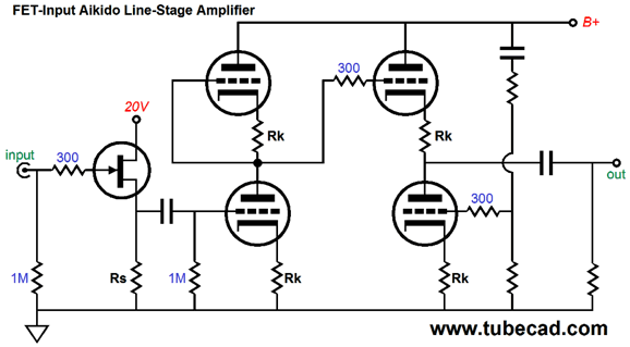
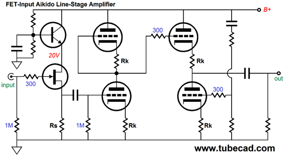
FETs and Aikido One problem we face is supplying the FET with its own low-voltage power-supply rail. If you own a PS-15, there's no problem, as it offers two low-voltage, regulated power supplies, along with one high-voltage power supply. On the other hand, we could steal the low voltage from the high-voltage B+ connection.
A simple capacitance-multiplier circuit can be used, as shown above. The high-voltage transistor, say a TIP50, must dissipate the lion share of heat, as it sees the lion share of voltage. But now that we have introduced the transistor to the Garden of Eden, why not go all the way?
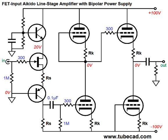
Brace yourself, as there is much to cover here. First, note the Bastode arrangement of the N-channel FET and the PNP transistor. As far as the FET is concerned, it is locked in a 20V vice; it can vary its current conduction and source voltage, but not its drain voltage. This varying current flow then travels through the PNP transistor down through the second Rs resistor, which terminates into the negative power-supply rail. Because the two Rs resistors match each other's value, no gain is realized; indeed, there must be some slight loss in gain. The Aikido then accepts the input signal and does its magic, but a bit differently than with a mono-polar power supply. For example, note the absence of the usual Aikido two-resistor voltage divider that provides the bottom output triode with is sampling of the power-supply noise. Where did it go? It wasn't needed, as the natural power-supply-noise null occurs at the output, as the bipolar power-supply rails hold equal, but opposite phase ripple, which when summed equal zero. If we need more gain, we can make the bottom Rs resistor much larger in value than the top Rs resistor, for we have about 100 volts to play with. Why would we need more gain? Say you want to use this as the first stage in a phono preamp or you plan on following this circuit with a solid-state output stage, making a fine hybrid power amplifier. Next Time
Since I am still getting e-mail asking how to buy these GlassWare software programs:
For those of you who still have old computers running Windows XP (32-bit) or any other Windows 32-bit OS, I have setup the download availability of my old old standards: Tube CAD, SE Amp CAD, and Audio Gadgets. The downloads are at the GlassWare-Yahoo store and the price is only $9.95 for each program. http://glass-ware.stores.yahoo.net/adsoffromgla.html So many have asked that I had to do it. WARNING: THESE THREE PROGRAMS WILL NOT RUN UNDER VISTA 64-Bit or WINDOWS 7 & 8 or any other 64-bit OS. One day, I do plan on remaking all of these programs into 64-bit versions, but it will be a huge ordeal, as programming requires vast chunks of noise-free time, something very rare with children running about. Ideally, I would love to come out with versions that run on iPads and Android-OS tablets.
//JRB |
I know that some readers wish to avoid Patreon, so here is a PayPal button instead. Thanks. John Broskie
Kit User Guide PDFs
And
High-quality, double-sided, extra thick, 2-oz traces, plated-through holes, dual sets of resistor pads and pads for two coupling capacitors. Stereo and mono, octal and 9-pin printed circuit boards available.
Designed by John Broskie & Made in USA Aikido PCBs for as little as $24 http://glass-ware.stores.yahoo.net/
The Tube CAD Journal's first companion program, TCJ Filter Design lets you design a filter or crossover (passive, OpAmp or tube) without having to check out thick textbooks from the library and without having to breakout the scientific calculator. This program's goal is to provide a quick and easy display not only of the frequency response, but also of the resistor and capacitor values for a passive and active filters and crossovers. TCJ Filter Design is easy to use, but not lightweight, holding over 60 different filter topologies and up to four filter alignments: While the program's main concern is active filters, solid-state and tube, it also does passive filters. In fact, it can be used to calculate passive crossovers for use with speakers by entering 8 ohms as the terminating resistance. Click on the image below to see the full screen capture. Tube crossovers are a major part of this program; both buffered and un-buffered tube based filters along with mono-polar and bipolar power supply topologies are covered. Available on a CD-ROM and a downloadable version (4 Megabytes). |
||
| www.tubecad.com Copyright © 1999-2014 GlassWare All Rights Reserved |
