| John Broskie's Guide to Tube Circuit Analysis & Design |
07 March 2015
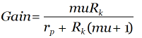
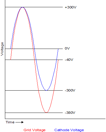
Cathode-Follower Power Amplifiers The problem is that it is not easy to build a cathode-follower output stage. Why not? The cathode follower does not deliver any voltage gain; in fact, it loses gain. This means that we must present the cathode follower with a huge input signal to get full power from it. The issue is not just high gain, but big voltage swings, peak-to-peak voltage swings that exceed the B+ voltage. In a nutshell, you now know why so very few cathode-follower-based power amplifiers were ever made and sold.
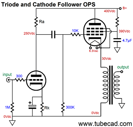
Let's use a schematic from my last post as starting point.
Here we see a input stage driving a cathode-follower output stage. The input stage would have to deliver plus and minus voltage swings of 300V to get full output from the cathode follower. But as the input stage's plate sits at 250V, it can only swing positively up by 150 volts before it hits the B+ voltage; and it can only swing down about the same 150 volts before its grid goes positive relative to its cathode. In other words, we only get one fourth of the potential power out of the cathode-follower output stage. One workaround is to use a bipolar power supply, which allows the driver stage to swing huge output voltages.
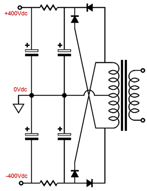
In the above schematic, the 6SN7 triode has a 600-volt window to operate within, allowing fairly large, say +/-250V, output swings. Making a bipolar, high-voltage power supply is not difficult, as center-tapped, high-voltage power transformers are common. In other words, if you can make a 400V monopolar power supply with a center-tapped transformer, you can also make a +/-400V bipolar power supply with the transformer.
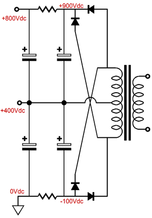
(The top two rectifiers could be replaced by a tube rectifier.) On the other hand, we can move the ground to the bottom, thereby creating a monopolar power supply with two B+ voltages.
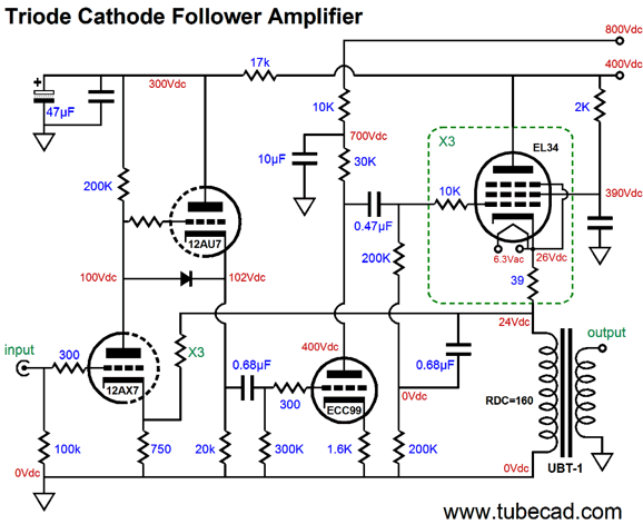
Okay, that's interesting, but what good does it in building a cathode-follower output stage? We can run both the input stage and the output stage with the 400V power-supply rail and run the driver stage with the 800V power-supply rail, as we see below.
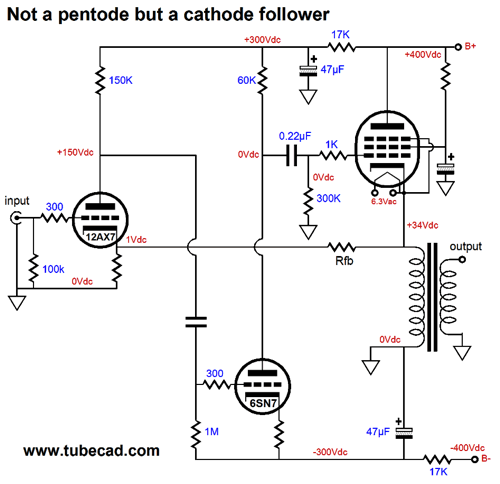
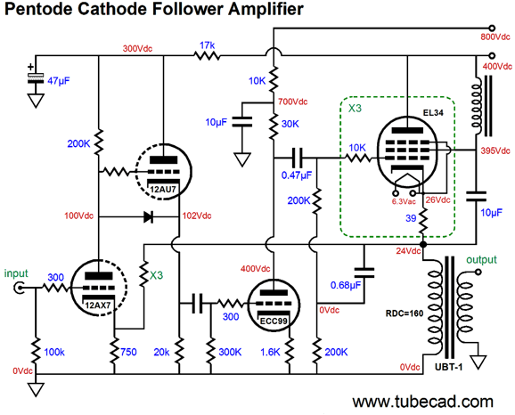
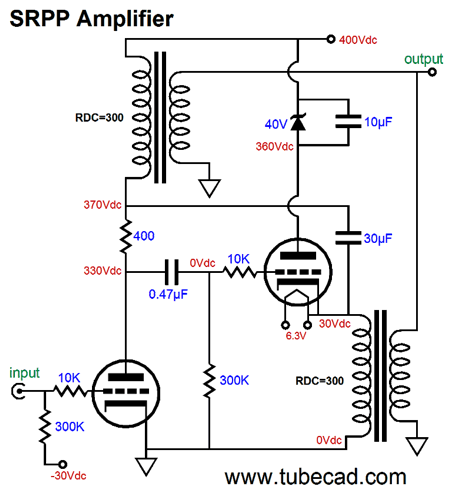
Note how the ECC99 driver triode sees 400V at its plate and works under a B+ voltage of 700V. This extra high B+ allows the ECC99 to drive the three EL34 output tubes to full output. The 12DW7 input tube holds two triodes, one a 12AX7 type and the other a 12AU7 type. We use the 12AX7 triode as the input tube and the 12AU7 as a cathode follower. Why? The ECC99-based driver stage will develop a good amount of Miller-effect capacitance, which the 12AX7's meager 1mA of idle current cannot cope with, but which the 5mA of idle current from the 12AU7 can. A feedback loop returns the signal at the output transformer primary to the 12AX7 cathode. Not a lot of negative feedback can be applied, say only 6dB worth. In fact, I would not use the feedback loop, as the cathode-follower output stage already produces a clean output. One key point is that the EL34 output tube is being used as a triode, not a pentode. Indeed, we are getting our cake and eating it too. Because the EL34 grid number-2 sees a filtered DC voltage, the EL34 behaves as if the plate also saw a filtered B+ voltage. If we want to make a true pentode cathode-follower output stage, we must attach the capacitor not to ground, but to the primary.
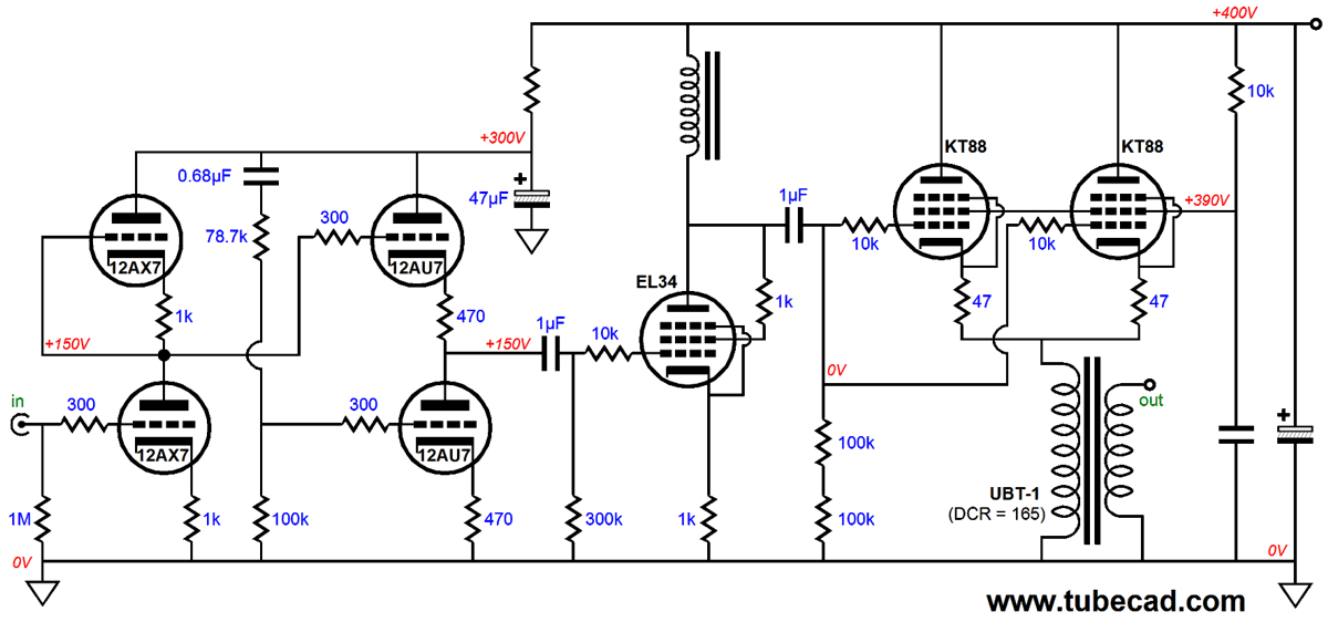
The choke replaces the resistor at grid 2, as we do not want to place a parallel load to the primary. With the inductor in place, the 10µF capacitor can swing up and down with the output signal, thereby maintaining a fixed cathode-to-grid-2 voltage, which is what pentode operation is all about. Another solution to the problem of getting big voltage swings from a limited B+ voltage is to use a choke/inductor load.
The EL34-based river stage is inductor loaded, which means that its plate can swing far above the B+ voltage. The two triode-connected KT88 (or KT100 or KT120) output tubes deliver about 15W of power. The Aikido input stage uses a 12AX7 input tube and a 12AU7 output tube. The EL34 could be replaced by another tube, such as the 12B4 or 6J5 or ECC99. A negative feedback loop could be added and many other small changes could be implemented. But the key point to this design is the elimination of the 800V power-supply B+ rail. Why? I hate 800V power-supplies.
I hate working on amplifiers with power supplies over 6ooVdc. I hate having the hair on my arm being electrostatically tugged by high-voltage. I hate fearing a lethal shock. I have friends who have heroically built tube power amplifier with 2,500V power supplies. I am impressed and relieved that I didn't have to be the one who first flipped the power switch. Extreme high-voltage stinks. This is not to say that 400V will not kill you; it can, as can 40V. But 400V is one quarter as nasty as 800Vdc. The only problem with the inductor, assuming it offers sufficient inductance and it can handle the idle current, is obtaining an audio-grade inductor. Audio-grade? An inductor suitable for use as an inductive load must be as good a transformer suitable for use as an audio output transformer. This is rare, as most chokes are meant to work at 100Hz or 120Hz, not 20kHz. In other words, care must be exercised in its construction and its core must be made from audio-grade iron. A rare bird indeed.
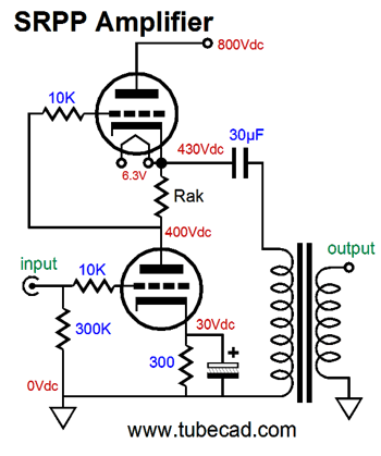
SRPP Power Amplifiers "I write the Tube CAD Journal and I created the GlassWare computer programs," I answered. "No, that's not it. What else have you done?" he replied. "Aikido, Platinum Brain Award, Janus regulator, Broskie cathode follower, Unbalancer, Broskie I-to-V converter… " I said. "No, that is not it. I remember now. You are the guy that doesn't know how a SRPP circuit works," he proclaimed. No doubt, my friends imagine that in reply I would quote Oliver Cromwell by saying, "I beseech you, in the bowels of Christ, think it possible you may be mistaken." But I didn't; instead, I said something along the lines of although I do know how many circuits work, such as current-measuring circuits, digital-to-analog converter circuits, and voltage-controlled oscillator circuits work, I stumble on the SRPP's two triodes and two resistors, for the topology is just too complex. Well, in spite of my famously limited comprehension of the SRPP, let's look into some possible SRPP power output stages, having been inspired by the last amplifier design, the one that used an inductor load. But first, let's start with a simple SRPP power amplifier.
Note the 800V B+ voltage, which is needed to allow big output voltage swings into the output transformer primary. I have already mentioned my fear and hatred of 800V power supplies, so let's now look at a bipolar power supply that offers +/-400V power-supply rails.
This is effectively the same amplifier as the one shown before, as the same amount of power output would obtain, with the same percentage of distortion and the same output impedance. The big difference is the input transformer, which could offer voltage gain; but which most importantly offers far greater PSRR, as the -400V power-supply rail's ripple will not get injected into the output signal. At the SRPP's output, the positive and negative power-supply rail voltage pretty much cancel—if and only if the bottom triode's grid and cathode see the same amount of ripple. Another way to get a good PSRR is to use an input stage with a staggeringly poor PSRR, paradoxically enough.
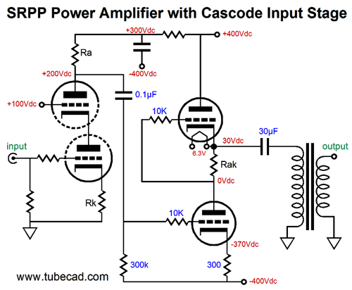
A cascode input stage, particularly one with an unbypassed cathode resistor, exhibits a truly poor PSRR figure, close to nothing, which is just what we need, as the RC filter that feeds the input stage from the B+ voltage terminates—not into ground—but into the negative power-supply rail. In other words, the bottom output tube will see the same amount of power-supply noise at its cathode as its grid sees, as that noise will be superimposed on the cascode's output signal. Now that we have the general idea, we can move on to a more fleshed-out implementation of the design.
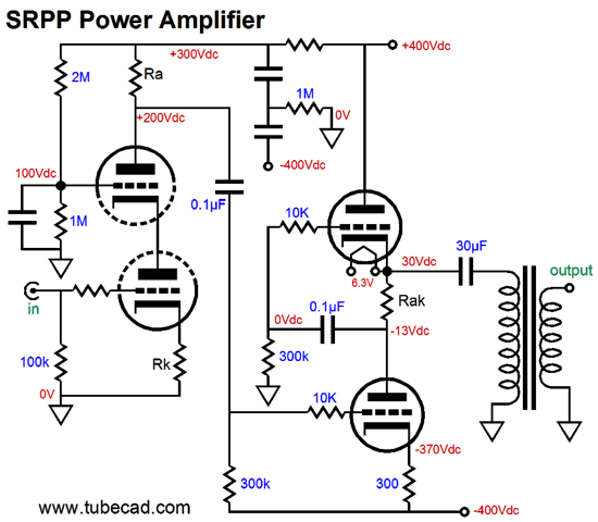
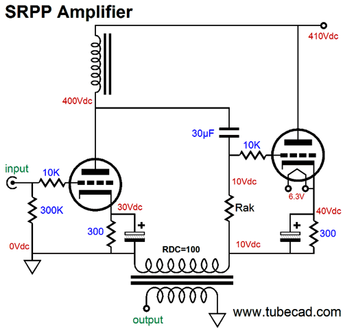
The single RC filter capacitor has been replaced by two capacitors. Why? Although you can buy 800V film capacitors, it is much easier to find 400V and 600V film capacitors. Understand that two 20µF capacitors in series equal one 10µF capacitor, albeit with a voltage rating twice as high. The 1M resistor is there only to ensure a somewhat fair voltage distribution between the capacitors. (The top capacitor will see 300V, while the bottom capacitor will see 400V. If you desire a true sharing of voltage, then each 20µF capacitor should be shunted with a 1M resistor.) Okay, let's get clever. Remember in the James Bond movie, From Russia with Love, where Bond carries a rifle in his briefcase.* The clever trick was to use a riffle that collapsed, allowing to fit into the small briefcase. Well, if we use an extra inductor, we can get away with only 400V of B+ voltage. Of course, we can never cheat physics; so, although we have halved the B+ voltage, we have doubled the current draw.
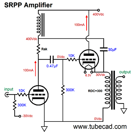
Both triodes idle at 100mA, so the peak symmetrical output current swing into the load equals 200mA. (An SRPP stage must be run in strict class-A operation, for if the bottom triode ever cutoff completely, the top triode loses its controlling master.) The current-sense resistor Rak develops the needed anti-phase signal for the right triode. Its resistance value must conform to the following formula: Rak = (2Rload + rp)/mu where rp stands for plate resistance and mu stands for the triode's amplification factor. The 30µF capacitor AC couples left triode's varying current conduction with the output load impedance. The output transformer's own DCR serves as a cathode-bias resistor for the right output tube. The left output triode gets required grid-bias voltage from a negative power-supply rail. Pause and reflect on what we have done here. It is as if we fit a six-foot tall man in a three-foot tall coffin. The price we paid was a doubling of the current flow and the need for an inductor and 30µF capacitor. A good deal, in my opinion. We can alter the arrangement, if we wish, as shown below.
Note how both tubes see the same cathode-to-plate voltage at idle. We can even use two output transformers, eliminating the needed for an inductor.
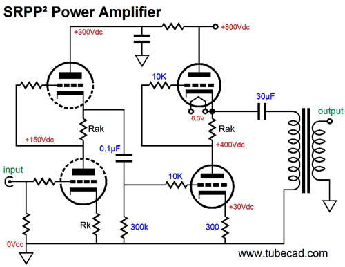
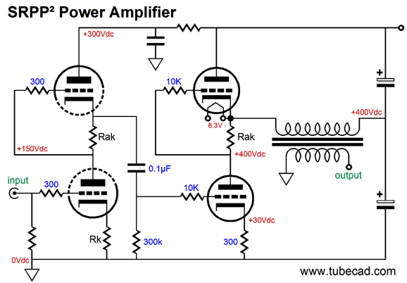
I have described SRPP² power amplifiers before, where two SRPP stages cascade.
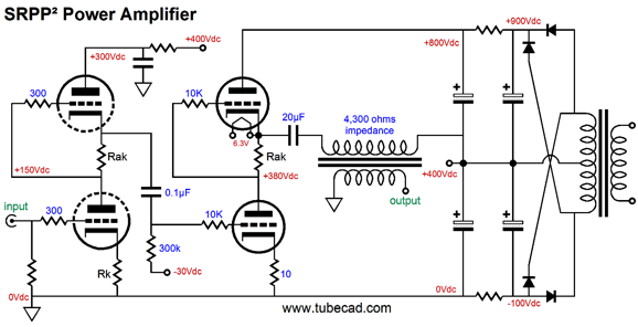
The above is a gratuitous use of the SRPP in the input stage, as the input's output signal could just as well have been taken from the bottom triode's plate as the top triode's cathode. In other words, I have sinned; for this SRPP neither pushes nor pulls, as the 300k load is far too high to force balanced push-pull operation form the two input triodes. Nonetheless, 99% of tube fanciers will be delighted by the design, as it just seems so right. Thus, I relent. I bow to public opinion, if only to curtail the flow of incoming e-mail. Robert Peel famously said, "Public opinion is a compound of folly, weakness, prejudice, wrong feeling, right feeling, obstinacy, and newspaper paragraphs," failing to add to the list the internet. If Winston Churchill were living today, I for one would be much happier; and no doubt, he would amend his famous saying, "There is no such thing as public opinion. There is only published opinion," with "that is posted on the internet." On the internet, the SRPP is like the most awesome circuit ever, dude. So, I sin, but I sin knowingly. We have two other problems with the above circuit: the 800V power supply and poor PSRR. We can overcome the last problem by not terminating the output transformer to ground.
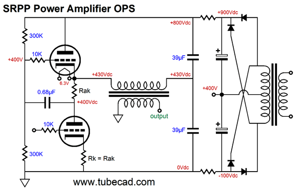
If the electrolytic capacitors are not left floating, but attach to the center tap, then a coupling capacitor will be needed, as we desired to avoid a DC offset across the primary. A workaround would be to use two film capacitors instead.
The two 39µF capacitors equal the single 20µF coupling capacitor they replaced, but the two film capacitors are much more likely to be matched in value and charge up equally than two electrolytic capacitors would. The two 300k resistors and the 0.68µF coupling capacitor were added to ensure that the two output tubes center in the 800V B+ voltage.
Next Time
*James Bond Having said that, if a AR-7's 22 long-riffle bullets had been custom-made by Q, so that they held gold or depleted uranium slugs and much higher-power smokeless powder charges, the AR-7 would be much more dangerous. (The 22 bullet was created for indoor use over 100 years ago, so a truly scary 22 bullet cannot be commercially made, as too many old, weak guns exist, which might burst with too powerful a charge.) Remember, twice the velocity, four times the impact, as KE = MV². Thus, if you have a heavier slug that travels at twice the velocity, watch out. I am fairly sure that they screwed up in giving Bond the AR-7; he should have had the AR-5, which was a bolt action, collapsible rifle that used the 22 hornet bullet, one of my favorites, as it is a real center-fire cartridge and is fantastically accurate.
User Guides for GlassWare Software
For those of you who still have old computers running Windows XP (32-bit) or any other Windows 32-bit OS, I have setup the download availability of my old old standards: Tube CAD, SE Amp CAD, and Audio Gadgets. The downloads are at the GlassWare-Yahoo store and the price is only $9.95 for each program. http://glass-ware.stores.yahoo.net/adsoffromgla.html So many have asked that I had to do it. WARNING: THESE THREE PROGRAMS WILL NOT RUN UNDER VISTA 64-Bit or WINDOWS 7 & 8 or any other 64-bit OS. I do plan on remaking all of these programs into 64-bit versions, but it will be a huge ordeal, as programming requires vast chunks of noise-free time, something very rare with children running about. Ideally, I would love to come out with versions that run on iPads and Android-OS tablets. //JRB |
Kit User Guide PDFs
E-mail from GlassWare Customers
High-quality, double-sided, extra thick, 2-oz traces, plated-through holes, dual sets of resistor pads and pads for two coupling capacitors. Stereo and mono, octal and 9-pin printed circuit boards available.  Aikido PCBs for as little as $24 http://glass-ware.stores.yahoo.net/ Support the Tube CAD Journal & get an extremely powerful push-pull tube-amplifier simulator for TCJ Push-Pull Calculator
TCJ PPC Version 2 Improvements Rebuilt simulation engine *User definable
Download or CD ROM For more information, please visit our Web site : To purchase, please visit our Yahoo Store: |
|||


| www.tubecad.com Copyright © 1999-2015 GlassWare All Rights Reserved |