| John Broskie's Guide to Tube Circuit Analysis & Design |
29 June 2015
New Three-Position Tilt Control
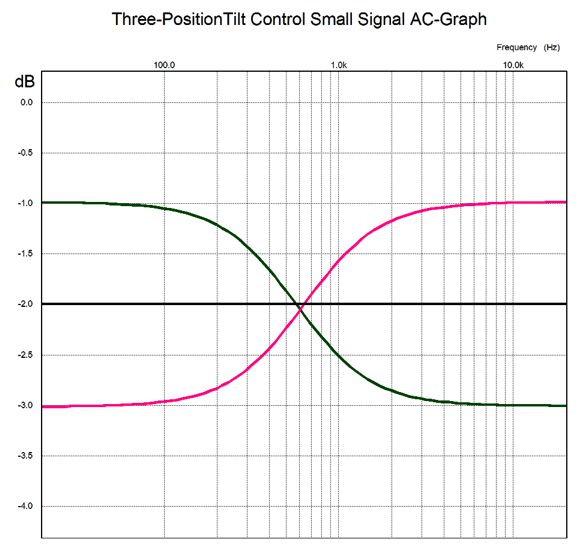
We need to be able to return the recording to flat, which is the Tilt-2 Control's job. The Tilt-2 Control's center position results in a flat frequency response, but is down -2dB. As the control twists clockwise, the highs go up by +1dB and the lows go down by -1dB. Conversely, as the control twists counterclockwise, the lows rise by +1dB and the highs drop by -1dB.
The Tilt-2 Control is a purely passive design, which entails a -2dB insertion loss and whose center frequency is 600Hz. Since most line-stage amplifiers offer too much gain, the loss of 2dB is actually welcome. The 600Hz frequency was chosen as being roughly the geometric center frequency. What is that? A geometric-mean frequency equally divides the octaves between a lower cutoff frequency and an upper cutoff frequency. In other words, it is the frequency that divides the frequency spectrum into equal portions of octaves. For example given a frequency range of 100Hz to 10kHz, the geometric mean frequency would be 1kHz, as 1,000Hz divided by 100Hz equals the same ratio as 10,000Hz divided by 1,000Hz, namely 10. We find the geometric mean frequency by multiplying the two bounding frequencies and then taking the square root of the product. For example, the square root of 20Hz x 20kHz is 632Hz. The Tilt-2 must come before the volume control potentiometer, as it takes in account the volume control's resistance in its functioning. In other words, a different potentiometer resistance requires a calculation of the parts values for the TIlt-2 Control. This is an improvement over the previous Tilt Control, as the former required a high-impedance termination, which no volume control could provide. In contrast, the Tilt-2 works with the volume control, as the volume control's impedance is part of the Tilt-2's circuit.
(By the way, back when I told some friends that I was designing my first frequency tilt control, I often heard the same advice: "Be sure to use a huge tilt; you know, something like plus and minus 12dB." I asked why such an extreme tilt and the answer was always the same same: "You have to hit them on the head, good and hard, as most audiophiles cannot hear that well." The most entertaining explication came from a friend with decades of work in the audio industry, who put it this way: "Look, the whole reason some guy is an audiophile is because he cannot hear that well. Ever notice that those who hear well, musicians, singers, conductors always own modest, cheap stereos instead of high-end gear. Why? Because they can hear, so they do not need expensive gear, just as the guy with 20-20 eyesight doesn't need eyeglasses or a real ladies-man does not need Playboy magazine or... The biggest mistake that you can make in audio is to get subtle, so give them a mega tilt, one that some nearly-deaf guy could hear." Against this universal advice, I went for subtle. I found with the previous Tilt Control that I seldom went beyond the 2dB tilt. No doubt there will be recordings that will make me itch for more tilting, but at least I got half way there.)
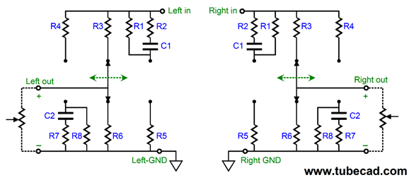
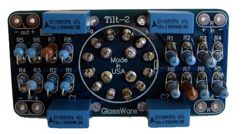
The Tilt-2 is a simple affair: a small PCB (1.4in by 2.8in), a 4-pol, shorting, three-position rotary switch, two capacitors and eight resistors. The assumption is that the signal source presents a low output impedance, which most modern electronic equipment does, but which some old pieces of tube audio gear do not, and that the volume control it cascades into presents a fixed resistance. Since the Tilt Control is passive, it does not require a power supply, mercifully. The GlassWare Tilt-2 Control kit is available now at the GlassWare-Yahoo store. It includes the PCB, rotary switch, and the four polypropylene capacitors and sixteen 1% metal-film resistors. It is available for three different volume control resistances: 20k, 50k, and 100k.
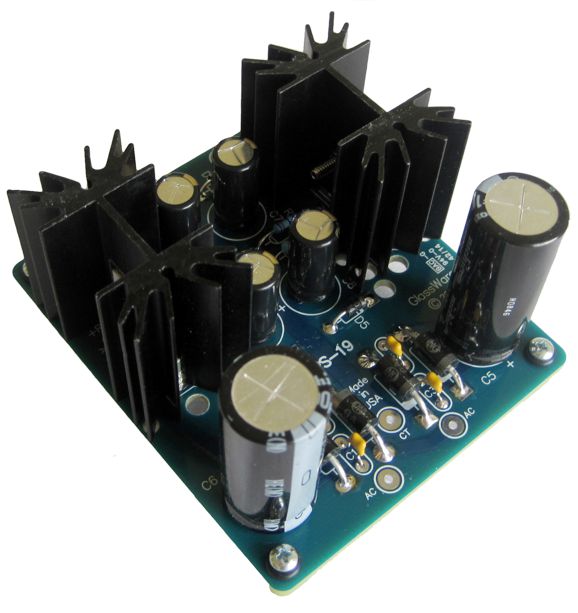
PS-19: A New Low-Voltage Bipolar Power Supply How do these two thermal resistances translate into actual performance? If the 3.7C/W heatsink were attached to a TO-220-encased resistor that dissipated 10W of heat, the heatsink would increase in temperature by 37C, as in 37 degrees celsius (centigrade). Now 37C is not that hot, as it is your core body temperature. But the 37C must be added to what ever temperature the heatsink was at prior to the resistor's heat generation. Usually, we assume 25C, 77 degrees in Fahrenheit, as the average room temperature. Inside a tube-filled chassis, this assumption might fall short of reality by 15C or more. On a hot summer's day, inside your tube power amplifier chassis, the ambient temperature might be closer to 50C (122 degrees in Fahrenheit). Ouch! As 50C added to 37C yields 87C, which produces a burning hot heatsink and, most probably, a toasted voltage regulator. My own self-imposed limit to heatsink temperature is 60C, as that is about as hot as I can bear to touch without gloves. So, if we work backwards, and if we assume 35C to be the internal enclosure temperature, and if we want to limit the 3.7C/W heatsink to no more than 60C, then the heat generating device, be it a voltage regulator or transistor or MOSFET or power resistor, cannot produce more than (60C - 35C) / 3.7C/W or 6.75W. If we use the taller heatsink, however, with is lower 2.6C/W thermal resistance, we can allow dissipation up to 9.6W. Of course, if the tall heatsink does not fit in the enclosure, its lower thermal resistance will not do us any good. Most OpAmp-based circuits draw relatively little current, say a total of 50mA, which against a voltage regulator's voltage drop of 4Vdc equals only 0.2W of heat. But if the OpAmp circuit is a headphone amplifier or a complex OpAmp-based circuit, then the larger heatsinks become a much bigger asset.
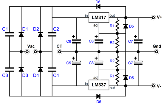
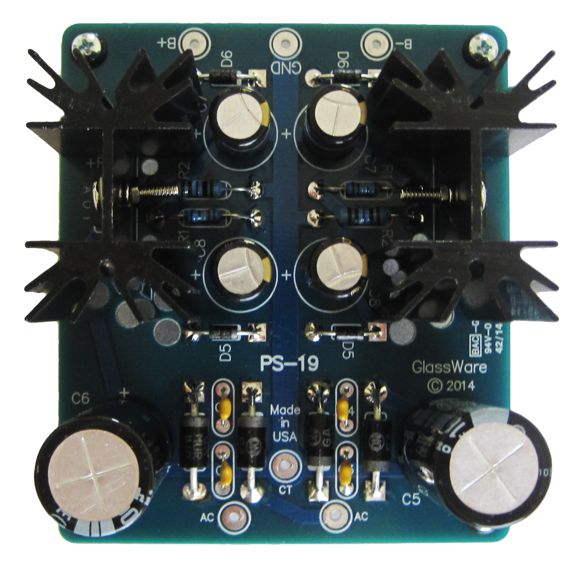
The PS-19's schematic is simple and straightforward. A full-wave bridge rectifier circuit converts the secondary's center-tapped AC voltage to bipolar DC voltages. Thereafter, the positive and negative adjustable regulators put out the desired rail voltages. The actual star of this show is the rectifier, a MUR410G, which is an exemplary 4A/100V rectifier. From its data-sheet:
A comparable rectifier is the 1N5401, which is a 3A/100V device with a recovery time so slow that none of the four data-sheets I could find specified its value, other than to state that it was a standard-recovery rectifier, which implies a recovery time of >500ns. The 1N5401's chief advantage is that is readily available and costs one fourth as much as the MUR410G. Co-staring in the PS-19 are capacitors C7 & C8, which are Panasonic FM series types, a low-ESR capacitor adored by many audiophiles—well, at least those in the know. The new PS-19 can deliver a bipolar voltages between +/-5V to +/-24V by selecting different values for resistors R2.
The PS-12 bipolar regulator kit is available, in several voltages, at the GlassWare-Yahoo store.
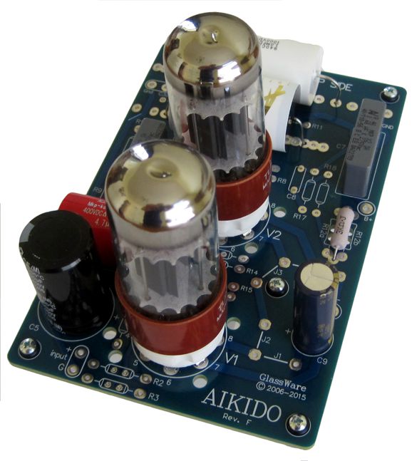
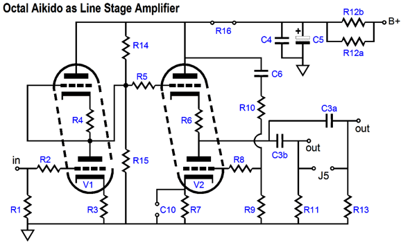
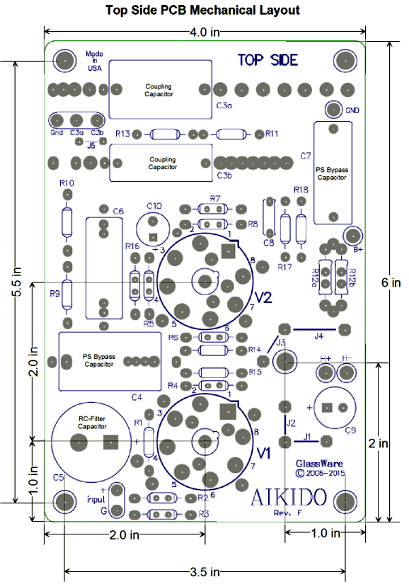
It's Back: Aikido Octal Mono PCB
The Aikido mono PCB now holds an RC filter for the B+ connection. This in itself will make building a single-ended amplifier or line-stage amplifier much easier. It also now holds a two-resistor voltage divider for setting the heater reference voltage to one fourth of the filtered B+ voltage. In addition, there is more room for the two output coupling capacitors.
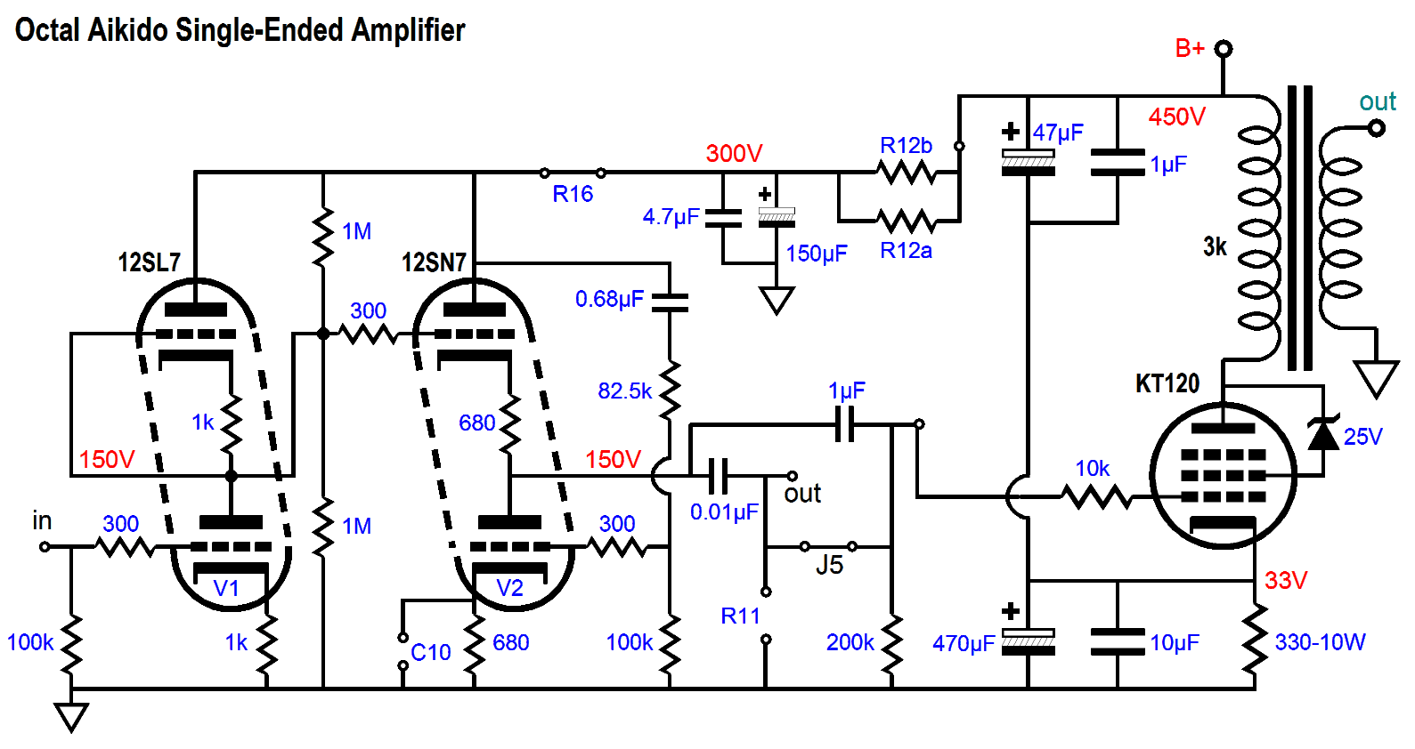
Resistors R12a & R12B and capacitors C4 & C5 define the RC filter for the B+ voltage. R16 is used when a headphone amplifier is needed or when driving a 600-ohm load. Speaking of making a single-ended power amplifier, here is one possibility:
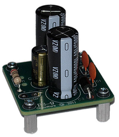
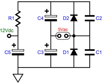
Aikido in the front, Aikido in the back. The 12SL7 provides enough gain to get close to the desired 1Vpk of input signal needed to drive the amplifier to full output, which would be about 15W, as the KT120 output tube's idle current squared against the 3k primary impedance divided by two implies an output of 15W. Why were 12SL7 and 12SN7 tubes used rather than 6SL7 and 6SN7 tubes? My assumption is that an unused 5Vac would be connected to a PS-9 voltage doubler, which would then deliver 12Vdc to the amplifier's frontend.
Well, couldn't 6SL7 and 6SN7 heater elements be placed in series and still used with the PS-9? No. These two tubes differ in heater current, whereas the 12SL7 and 12SN7 share the same heater voltage, so their differing current draws does not matter. On the other hand, a 6SL7 draws 300mA of heater current, as does a 12SN7, so those two could be placed in series and used with an 18Vdc power supply (a PS-9 fed by a hot 6.3Vac winding, for example*). I see that I didn't specify the values for resistors R12a & R12B. A quick guess would be let one be 47k and the other be 51k (1W to 3W devices). The output stage consist of the lone KT120 and a 3k output transformer. The idle current is set to about 100mA by the 330-ohm cathode resistor. The resulting dissipation is close to 45W (we can expect some voltage drop across the primary, due to its DCR). The collection of four capacitors both bypass the cathode resistor and inject a small portion of power-supply noise into the cathode, so an Aikido-like null in power-supply noise obtains in the secondary and at the speaker.
Of course, the Aikido Octal Mono PCBs can be used to build a line-stage amplifier. For this application, nothing beats the 6SN7, 12SN7, and 12SX7. I would avoid the 6AS7, 6BL7, 6BX7, and 6H30Pi. Why? The 6SN7 was designed with audio applications in mind, so great effort was put into ensuring that both triodes matched each other within the envelope. This is not true with the 6BX7, which often holds grossly mismatched triodes. Perhaps one day, someone in Russia or the Czech Republic will design a new octal twin triode tube, say one constructed along the lines of the 6DJ8 in terms of it using a grid frame and like the 5963 and 5965 in terms of the special treatment of its sleeping-disease-free cathode, but offering a mu of only 12 or 16. Such a tube could prove thrilling in audio applications. (Another tube that I would like to see the Russian revive or remake is the 8417, a fantastically good tube and one of the last true advancements in tube design, as is revealed by its high number. So while a KT120 is fine, let's see something like a 8417R, with "R" standing for Russian.) If a beefier output tube is required, say for a headphone amplifier application, then the 6BL7 and 6H30Pi are the best choices. When using the mono PCBs, the best approach to building a headphone amplifier is to use either two mono headphone jacks or a four-pin connector to attach the headphones. When building a dual mono line stage amplifier, do go the whole way. By that I mean do give each mono Aikido PCB its own power supply and power transformer. They can be housed in the same enclosure and the case can be grounded via two 1k resistors, one attaching to each mono power-supply ground. If you are not driving mono-block power amplifiers or if you are passing the output signal off to an electronic crossover, do not bother with dual mono setups. To get the most from dual mono line stage amplifiers the power amplifiers should also be dual-mono amplifiers that do not directly ground the signal ground to the house ground. Yes, it gets complicated fast. The Aikido Octal Mono PCB and kit are available at the GlassWare-Yahoo store. And are now available in singles.
And Now for Our Special Feature
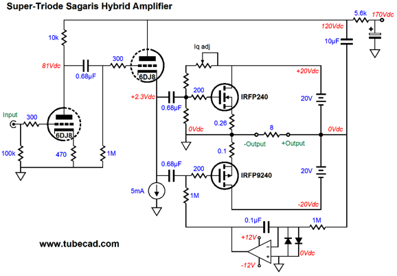
The N- and P-channel MOSFETs have their sources grounded and their drains attach to a floating power supply, i.e. a power supply that isn't grounded. The result is that an input signal delivered to their gates will prompt amplification and phase inversion at the output, which is taken at the power supply's midpoint. The dissimilar source resistor values is intentional. The N-channel MOSFET exhibits more transconductance than the P-channel MOSFET, so we must give the N-channel more of a handicap, so that its effective transconductance equals that of the P-channel MOSFET. (The first MOSFET power amplifier that I built was back in the 1970s, while a college student. It held one N-channel MOSFET and two P-channel MOSFETs, which wasn't ideal, as one N-channel to to 1.7 P-channel MOSFETs would have been closer to ideal but it was still better than just two MOSFETs.) The 10µF capacitor locks the triode plate to the amplifier's output (in AC terms), so the triode establishes its control over the pair of MOSFETs. As this circuit stands, the distortion is low and very single-ended like at 1W of output; but at full output, about 16W, the distortion climbs fast. One workaround is to use an additional triode.
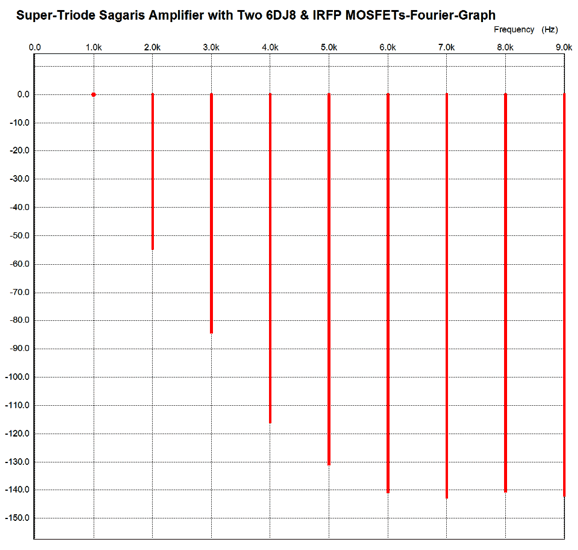
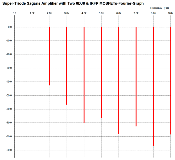
This isn't the only way to add an extra triode, as we could have used a negative-feedback loop from the output to the input triodes' cathode. (Note that this version does not invert the output signal's phase, whereas the first version did.) I wanted, however, to stick to plate feedback, rather than the conventional cathode feedback. In my SPICE simulations of the above circuit, I doubled up on the MOSFETs, so four per channel were used. I also ran them hard, with 475mA of idle current per device, making this amplifier just a tad less than class-A. If we limit the output power to 14W, however, it is a strict class-A, push-pull amplifier. Was that magic? No. Every class-AB push-pull amplifier is a class-A amplifier—up to a certain wattage that is. Often, the class-A limit is exceeded at only a few milliwatts, but up until that threshold output wattage is exceeded, the amplifier runs in class-A. In other words, our 14W class-A transforms into a class-AB amplifier once we try to get more than 14W from it. Here is the SPICE-generated Fourier graph for this amplifier at 1W into 8 ohms at 1kHz.
And here is the Fourier graph for this amplifier at 16W into 8 ohms at 1kHz.
Not great, but probably quite pleasant to the ear, as strong single-ended flavor predominates.
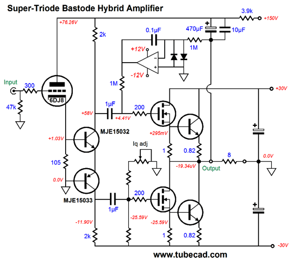
Super-Triode Bastode Hybrid Amplifier The following design aims to undo those three problems.
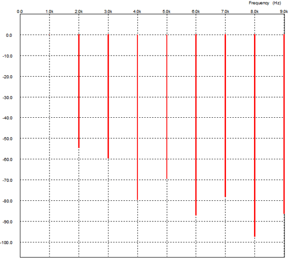
Let's work backwards. The power supply is firmly grounded, so no floating. Only two N-channel power MOSFETs are used. The power transistors only tag along and do not conduct at idle, but only turn on after the MOSFETs leave the class-A window operation. These "afterburner" transistors are used to establish a constant-transconductance output stage, which avoids the gm-doubling distortions. The bastode transistors, MJE15032 & MJE15033, are used to add extra gain and phase inversion. Once again, an OpAmp works inside a DC servo to keep the output voltage centered at zero at idle. The potentiometer sets the idle current to a relatively low 295mA. The triode's cathode is not loaded by a constant-current source, but a simple cathode resistor. The 6DJ8 provides the output stage's impetus—its impelling force, its drive, its input signal—and its negative feedback mechanism; namely, its plate resistance and amplification factor. What happens at startup, when the triode is cold and not conducting? Nothing much, as the internal coupling capacitors save the day and your speakers. Okay, how well does this amplifier perform? Here is the Fourier graph for 1W output into 8-ohm load at 1kHz.
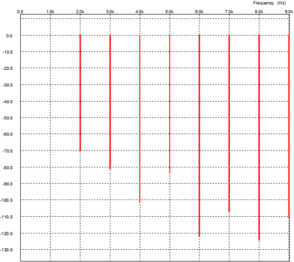
Not too shabby. Perhaps, bit rougher than I would like. Nonetheless, it still presents a fairly single-ended harmonic structure and the THD is below 0.1%. Now, let's look at what happens at full output, which is 36W.
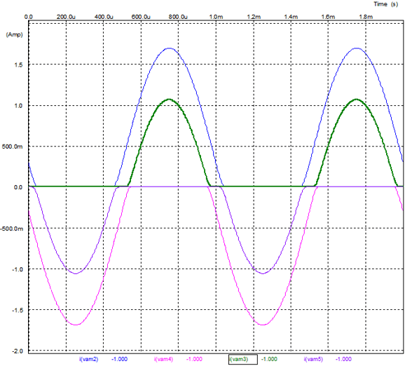
Still not too shabby. How well does the timing of the after-burner transistors go? Here is the conduction graph.
I will stop here. Not because we have arrived at perfection, but due to it getting late and my fingers giving out. No doubt there will be more along these lines next time.
Next Time
*PS-9 Fed by a Hot 6.3Vac Winding
User Guides for GlassWare Software
For those of you who still have old computers running Windows XP (32-bit) or any other Windows 32-bit OS, I have setup the download availability of my old old standards: Tube CAD, SE Amp CAD, and Audio Gadgets. The downloads are at the GlassWare-Yahoo store and the price is only $9.95 for each program. http://glass-ware.stores.yahoo.net/adsoffromgla.html So many have asked that I had to do it. WARNING: THESE THREE PROGRAMS WILL NOT RUN UNDER VISTA 64-Bit or WINDOWS 7 & 8 or any other 64-bit OS. I do plan on remaking all of these programs into 64-bit versions, but it will be a huge ordeal, as programming requires vast chunks of noise-free time, something very rare with children running about. Ideally, I would love to come out with versions that run on iPads and Android-OS tablets. //JRB |
Kit User Guide PDFs
E-mail from GlassWare Customers
High-quality, double-sided, extra thick, 2-oz traces, plated-through holes, dual sets of resistor pads and pads for two coupling capacitors. Stereo and mono, octal and 9-pin printed circuit boards available.  Aikido PCBs for as little as $24 http://glass-ware.stores.yahoo.net/ Support the Tube CAD Journal & get an extremely powerful push-pull tube-amplifier simulator for TCJ Push-Pull Calculator
TCJ PPC Version 2 Improvements Rebuilt simulation engine *User definable
Download or CD ROM For more information, please visit our Web site : To purchase, please visit our Yahoo Store: |
|||


| www.tubecad.com Copyright © 1999-2015 GlassWare All Rights Reserved |