| John Broskie's Guide to Tube Circuit Analysis & Design |
16 January 2016
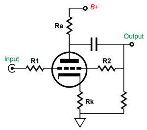
Anode-Plate Follower "One that achieves unexpected recognition or success." Close, but quite not there yet, as "sleeper" here means something that should be recognized and that should be successful, but as too few know of its true potential, it languishes, needlessly neglected, largely unknown. Books, movies, LPs, bottles of wine—all can be examples of sleepers. And ignoring the the anode/plate follower circuit is a big mistake, as it can prove extremely useful in tube-audio design. The anode/plate follower circuit appeared here before, starting back in the year 1999, then in blog 105, and last time in blog 315. Definitely worth rereading. The anode/plate follower circuit is based on the grounded-cathode amplifier and its closest solid-state analogy is the inverting OpAmp circuit.
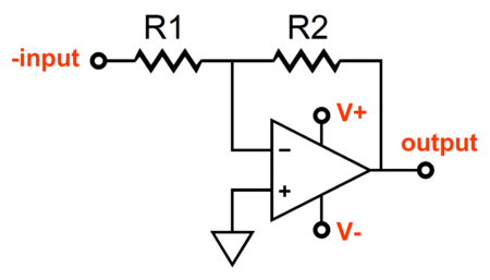
This is a ubiquitous OpAmp circuit and with good cause. Its input signal gets inverted the output; the input impedance equals the value of R1; and resistors R1 & R2 set the gain, where Gain = R2/R1. If R1 is bigger in value than R2, the inverting amplifier will deliver a gain below-1, which can prove useful. In many ways, the inverting configuration is the preferred way to run an OpAmp, as the phase inversion as a good feature, as positive feedback is less likely than it is in a non-inverting circuit. There is an old saying in electronics, "Whenever possible: invert." In addition, the OpAmp's input stage is happier, as both of the OpAmp inputs are locked at ground level, giving the input stage's constant-current source and cascoding circuitry plenty of voltage headroom within which to work. The result is often lower distortion.
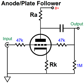
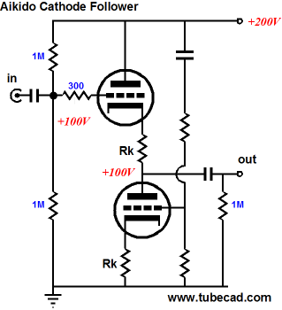
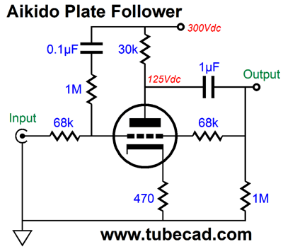
The tube-based anode/plate follower circuit roughly follows the same gain formula as the inverting OpAmp circuit: Gain = R2/R1. Due to the far lower open-loop gain of the grounded-cathode amplifier, however, the above formula is only roughly right, as the final gain will invariably fall a tad short of the resistor ratio. For example, the resistor ratio in the following plate follower implies a gain of -1 (odB), but we can expect a small insertion loss. One workaround is to add a cathode follower to the mix. This is usually an easy thing to do, as many audio-type triodes come two to the tube envelope, such as the 6DJ8, 6SN7, and 12AU7...
The addition of the cathode follower unburdens the input grounded-cathode amplifier stage, as it frees it from the job of driving the external load impedance. Okay, now that we are all familiar with plate follower circuit, we can move on to new frontiers.
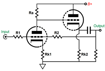
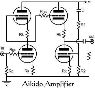
The Aikido Plate Follower Thus, the need for brute strength is replaced by subtlety and sneakiness. Well, in my electronic designs, I have sought to replace brute force (and complexity and expense) with subtle, and sneaky techniques that sidestep problems such as power-supply noise; hence, the "Aikido" title in so many of my designs. Thus, there is no one Aikido circuit, but rather a family of Aikido circuits. For many, the following is the one, true Aikido amplifier. Well, it certainly is an Aikido-inspired circuit.
A better name would have been the symmetrically-loaded grounded-cathode amplifier cascading into an Aikido cathode follower circuit.
While this alternate name is more accurate, it is also a mouthful. What follows is an Aikido plate follower circuit. Like the Aikido circuit above it, this circuit largely ignores the power-supply noise, as the small portion of power-supply noise injected at the grid creates an anti-phase amplification of the sampling and creates a power-supply noise null at the circuit's output.
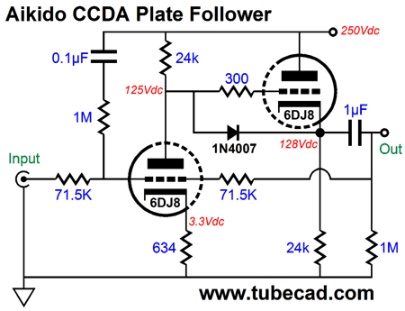
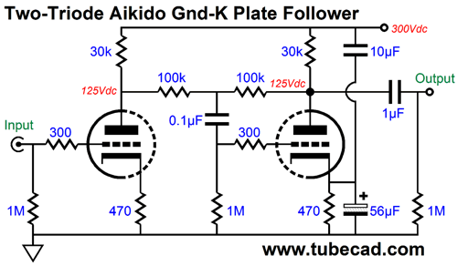
I failed to designate the triode used in this example, but it sure looks like I had a 6DJ8 in mind, as the voltages and part values suit a 6DJ8/6922/E88CC. This Aikido plate follower will present a gain close to -1 and offer an exemplary PSRR figure. Its output impedance, on the other hand, it not so hot. The following variation makes use of a cathode follower to achieve at least three goals: lower output impedance, a constant-current draw, and lower distortion.
Now a 6DJ8-based cathode follower usually offers an output impedance of about 100 ohms; this Aikido plate follower's output impedance will prove far lower, as the negative feedback loop will lower the impedance to below 10 ohms. This circuit would make an excellent core to a tube-based mixer. For line-stage use, o ne potential problem, however, might be its relatively low input impedance (roughly 75k), which would shunt a volume control potentiometer output, throwing the attenuation curve off. This input impedance may also drag down the signal source. One workaround is my alternative variation on the circuit.
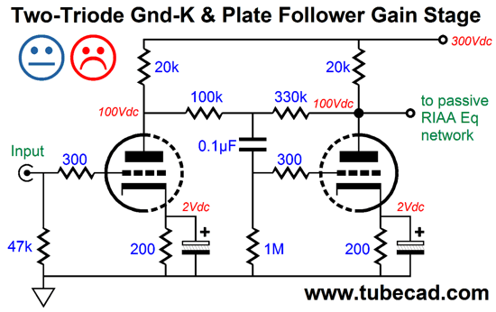
Here the input impedance equals the 1M grid resistor and the Aikido magic obtains from the two cathode-resistor bypass capacitors, 56µF & 10µF, which inject enough power-supply noise into the plate follower's cathode to create a power-supply-noise null at the output. Sadly, the ratio between capacitors must be found afresh with each change in parts or triodes used. I wish that I had come up with this circuit 30 years ago, as I used the following circuit in a phono stage amplifier that placed passive RIAA equalization network between two +30dB gain stages.
My goal was to get more gain than the input stage could deliver and a lower output impedance from a single 6DJ8 tube. Unfortunately, the PSRR stinks, as it comes in at only about -6dB.
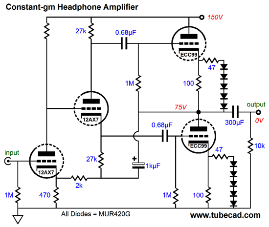
Complaints About Constant-gm Output Stages
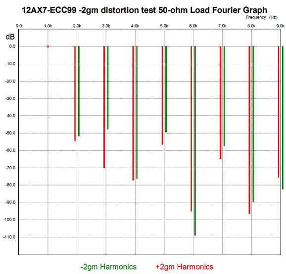
The above is a simple tube-based headphone amplifier that runs its push-pull output stage in class-AB. The added two 47-ohm resistors and 10 rectifiers serve to make a closer approximation to a constant-gm output stage. How well do they work? The answer is shown in the following Fourier graph generated by SPICE simulations of the amplifier without -2gm features (in green plots) and with -2gm features (in read plots).
What do wee see? We see that with the exception of the 6th and 9th harmonics, the -2gm version offers lower distortion. In my view, the key harmonics are the 3rd, 5th, and 7th. The over 20dB reduction in 3rd harmonic distortion must prove especially ear pleasing. Alas, I have run out time now, as I could show similar graphs for -2gm-enhanced Circlotron and OTL power amplifiers.
Next Time
User Guides for GlassWare Software Since I am still getting e-mail asking how to buy these GlassWare software programs:
For those of you who still have old computers running Windows XP (32-bit) or any other Windows 32-bit OS, I have setup the download availability of my old old standards: Tube CAD, SE Amp CAD, and Audio Gadgets. The downloads are at the GlassWare-Yahoo store and the price is only $9.95 for each program. http://glass-ware.stores.yahoo.net/adsoffromgla.html So many have asked that I had to do it. WARNING: THESE THREE PROGRAMS WILL NOT RUN UNDER VISTA 64-Bit or WINDOWS 7 & 8 or any other 64-bit OS. One day, I do plan on remaking all of these programs into 64-bit versions, but it will be a huge ordeal, as programming requires vast chunks of noise-free time, something very rare with children running about. Ideally, I would love to come out with versions that run on iPads and Android-OS tablets.
//JRB |
Kit User Guide PDFs
And
High-quality, double-sided, extra thick, 2-oz traces, plated-through holes, dual sets of resistor pads and pads for two coupling capacitors. Stereo and mono, octal and 9-pin printed circuit boards available.
Designed by John Broskie & Made in USA Aikido PCBs for as little as $24 http://glass-ware.stores.yahoo.net/
The Tube CAD Journal's first companion program, TCJ Filter Design lets you design a filter or crossover (passive, OpAmp or tube) without having to check out thick textbooks from the library and without having to breakout the scientific calculator. This program's goal is to provide a quick and easy display not only of the frequency response, but also of the resistor and capacitor values for a passive and active filters and crossovers. TCJ Filter Design is easy to use, but not lightweight, holding over 60 different filter topologies and up to four filter alignments: While the program's main concern is active filters, solid-state and tube, it also does passive filters. In fact, it can be used to calculate passive crossovers for use with speakers by entering 8 ohms as the terminating resistance. Click on the image below to see the full screen capture.
Tube crossovers are a major part of this program; both buffered and un-buffered tube based filters along with mono-polar and bipolar power supply topologies are covered. Available on a CD-ROM and a downloadable version (4 Megabytes). |
||


| www.tubecad.com Copyright © 1999-2016 GlassWare All Rights Reserved |