| John Broskie's Guide to Tube Circuit Analysis & Design |
27 February 2016
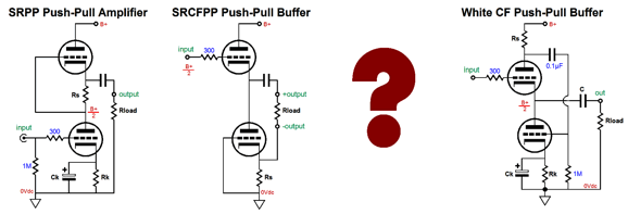
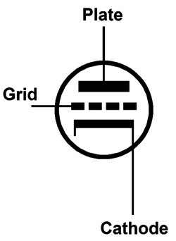
The Missing "Lazy" Link I thought I had pretty much exhausted the topic. I was wrong. Through a recent e-mail exchange with a bright reader, Colin, I realized that another circuit topology could be added to the list. It differs from previously mentioned topologies in that while it accepts a single unbalanced input signal, this signal must be fed into two input ports, not one. In addition, it can be run outside the confines of strict class-A operation, as class-AB operation is possible. Furthermore, it is not load dependent. (Strictly speaking, therefore, this means that this new circuit does not truly belong to the trinity of reflexive circuits: SRCFPP, SRPP, and White cathode follower, as there is no "R," no Reflexive, no current-sense resistor.) It also differs in that the circuit is so new that it does not have a name. But first, let’s make a quick review of how we can prompt a change in current flow from a triode. We can increase or decrease the plate voltage or the grid voltage or the cathode voltage. Each change in voltage will result in a change in the triode’s current flow. Thus, we can say that each triode’s three elements (grid, cathode, and plate) exhibit a transconductance, a gm. The plate’s gm is equal to 1/rp, where rp stands for the triode’s plate resistance. For example, a 1V increase in plate voltage will force the triode’s conduction to increase by 1V/rp, just as would a resistor in the same situation. The grid’s gm, which is what the tube manual lists) is equal to its amplification factor (mu) divided by its plate resistance, or mu/rp. And the cathode’s gm is equal to (mu + 1) / rp.
Normally, we pretend that the cathode’s gm is the same as that of the grid. This lazy shortcut is not a big deal when the triode’s mu is high, say over 30. With a low-mu triode, like the 6AS7, however, this shortcut assumption is drastically off. For example, the 6AS7’s mu is 2 and its rp is 280 ohms. Thus, the grid’s gm equals 2/280 or 1/140 (7.1mA/V), while its cathode’s gm equals 3/280 (10.7 mA/V). In other words, the 6AS7 cathode is 1.5 times more effective than the grid in controlling the flow of current through the 6AS7 triode. With a 12AX7, on the other hand, the cathode is only 101/100 or 1.01 times more effective than its grid.
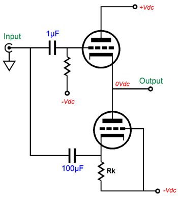
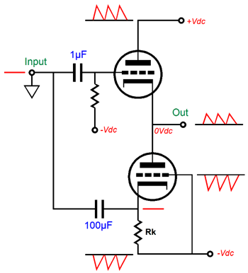
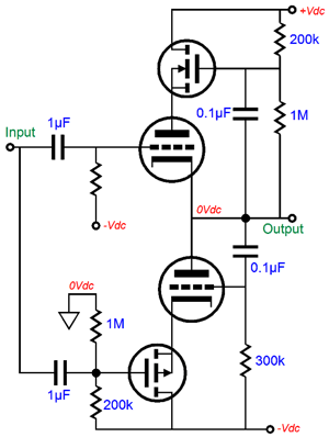
Why does the cathode exhibit greater transconductance? Think about it, when we alter the cathode voltage we also alter the cathode-to-plate voltage. If we increase the cathode voltage by 1V, we not only effectively make the grid 1V more negative than the cathode, but we also make the cathode-to-plate voltage drop by 1V. In other words, the cathode’s gm is equal to the grid’s gm and plate gm combined. This disparity in gm only holds true for the triode. With a pentode, transistor, MOSFET, and FET, a change in plate or collector, and drain voltage makes little—if any—difference in the device’s current conduction. We must also review the current-phase relations due to the changes in triode grid, cathode, and plate voltages. Both the grid and plate work in phase with the current flow. In other words, an increase in grid or plate voltage results in an increase in current conduction. In contrast, an increase in cathode voltage will result in a decrease in current flow. This anti-phase relation between cathode and grid can be exploited in push-pull output stage, as it could allow for the use of an unbalanced input signal, while retaining true push-pull operation. The schematic shown below displays how both the top and bottom triodes could be driven in a push-pull fashion in spite of no phase splitter and no balanced input signals.
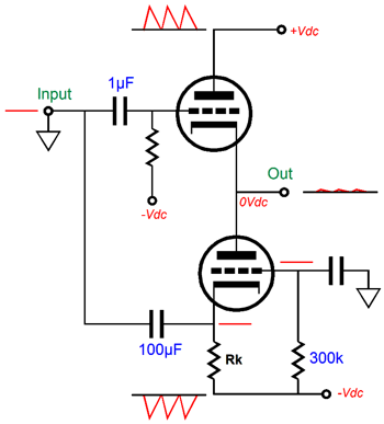
As this circuit stands, it does not work that well; indeed, its performance is embarrassingly poor. For example, given the same input signal, the bottom triode is grossly overdriven, as the bottom triode’s cathode exhibits a greater gm than the top triode’s grid. Second, since the output stage's output follows the top triode’s grid, the top triode’s grid must see a much larger input signal than the bottom triode’s cathode. Third, the top triode’s grid offers a staggeringly high input impedance, while the bottom triode’s cathode presents a brutally low input impedance. Fourth, the output impedance presented by the top triode is much lower than presented by the bottom triode’s plate. Fifth, this topology’s PSRR is poor, as the bottom triode’s grid sees all the power-supply noise riding on the negative power-supply rail, but its cathode is shielded from this noise, making this noise an unintended input signal that gets amplified. Okay, I will admit that this topology does not look too promising, as we have five big problems to fix. Let’s tackle the last problem, its poor PSRR, first. As long as only the bottom triode's grid or cathode sees the negative power-supply noise, that noise gets amplified.
The easy solution is to retain the DC coupling of the bottom triode’s grid to the negative power-supply rail, but AC couple it to ground. Now, both cathode and grid are grounded referenced.
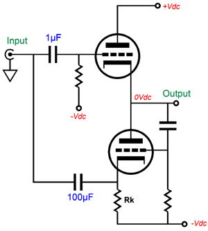
Much better, but not perfect, as the top triode's plate still see all the power-supply noise riding on the positive power-supply rail. Thus, some of this noise will leak out of the output. Fixing the disparity between output impedances of the top and bottom triodes requires that both output triodes react equally to an externally applied voltage to the output. In other words, if we force the output 1V more positive, then the top triode’s conduction should decrease by the exact same amount as the to bottom triode’s increases. One step in this direction is to AC couple the bottom triode’s grid to the output stage’s output, not to ground.
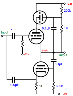
If the output is forced +1V, then the bottom triode’s grid will also be forced 1V more positive. Thus, both top and bottom will react in anti-phase to the +1V change in output voltage. AC coupling the bottom triode’s grid to the output granted us a bonus, as this configuration works to equalize the drive voltage requirements between top and bottom triodes. For example, say that the input signal swings up 10V and the output swings up only 7V. This means that the top triode’s cathode-to-grid voltage decreases by 3V, the same amount as the bottom triode’s cathode-to-grid voltage increased. In other words, the bottom triode’s cathode saw the 10V increase in voltage, while its grid saw a 7V increase relayed from the output, so effectively both top and bottom triodes see the same drive signal amplitude, which differ in current-phase results, resulting in push-pull operation. Unfortunately, as the cathode’s gm is greater than the grid’s, the top triode will over react, decreasing its conduction more than the bottom triode will increase its conduction. One workaround is to relay the change in output voltage to the top triode’s plate, so that its cathode’s gm falls to mu/rp. How can we do that? The following is one possible solution.
An added advantage to this arrangement is that it greatly improves the output stage’s PSRR, as the N-channel MOSFET shields the top triode’s plate from the positive power-supply rail noise. Think of it as free power-supply filtering with a capacitor-multiplier circuit. Note how the top triode functions under a fixed cathode-to-plate voltage at all times. As the output swings up and down, so too does the cathode-to-plate voltage. Making the input impedances for the top and bottom triodes equal can be had by making the top triode’s input impedance equally low as the bottom triode’s cathode or by making the bottom triode’s cathode input impedance equally high as the top triode’s grid. Ideally, the latter approach will be realized, as a low input impedance means a huge pair of coupling capacitors. The following schematic shows one possible solution.
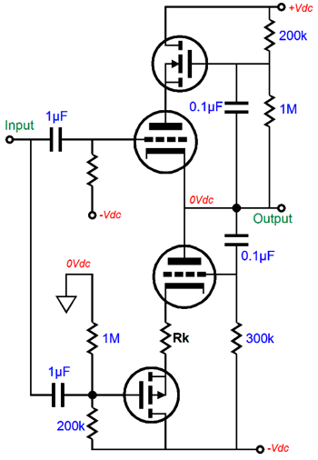
The P-channel MOSFET presents a very high input impedance, while its source presents a very-low output impedance, usually less than 1 ohm. The only remaining problem is that the bottom output triode is still overdriven, as its cathode exhibits 1.5 times more gm than the top triode’s grid. The solution is to weaken the bottom triode’s gm until it matches the top triode’s; and the easiest means to this end is to add a cathode resistor to the bottom triode.
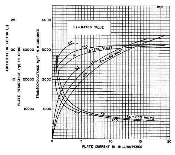
How big in value must this resistor be? The following formula establishes the correct value. Rk = rp/mu - rp/(mu +1)* Well, at least that is the theory. The thing is that triode’s gm and rp vary over its range of operation. Its amplification factor (mu) is the most constant of the three. But it, too, varies. For example, a far more linear triode than the 6AS7 is the 6SN7. Here is a graph of the 6SN7's rp, gm, and mu.
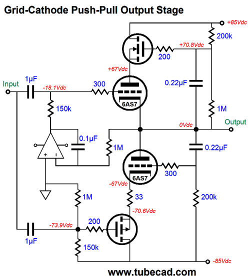
Note that its mu is fairly constant above 8mA. Its gm and rp, however, are not. With the 6AS7, its mu is, according to the tube manual, 2; its rp, 280 ohms. Plugging these numbers into the formula yields 46.7 ohms. So, it looks like we can use a 47-ohm resistor. In SPICE simulations, however, the optimal value was closer to 33 ohms. And no doubt reality would prefer another value. (SPICE triode models usually assume a perfectly constant mu, which reality fails to deliver.) I ran the 6AS7 SPICE model within a tube-tester SPICE circuit and it resulted in a mu of 2.07 and an rp of 197 ohms at 67V and 100mA. (My own True-Curves math model of the 6AS7 resulted in a mu of 2.14 and an rp of 256 ohms.) Using the SPICE models result in the formula gave 33 ohms as the solution for Rk. We now arrive at the following schematic that shows the complete, workable transformation.
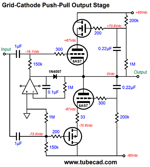
Where to start? The DC servo is as good a place as any. The OpAmp is configured as an integrator that monitors the DC offset present at the output and applies a correcting DC voltage to the top triode’s grid until the DC offset is eliminated. Frequencies above 1.6Hz are ignored. One problem with the DC servo is that it only works as long as both triodes are present and conducting. What happens if one triode heats up faster than its partner? Not good. One solution is to add a diode to the circuit.
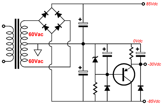
Note how the OpAmp’s output voltage is normally many negative volts relative to the output at idle. If the top triode is slow to conduct, then the OpAmp’s output will slam up positively, making the diode forward biased, which connects the OpAmp’s output to the output stage’s output. The OpAmp must be robust enough to deliver enough current to pull up agains the bottom triode's plate. On the other hand, if the bottom triode is slow to conduct, then the top triode will pull up excessively. But all is not lost as long as the DC servo can swing sufficiently negative to cut off the top triode’s conduction. This brings up the issue of powering the OpAmp. Most OpAmps are run off +/-12Vdc or +/-15Vdc. This will not work for us here, as the 6AS7 must see a grid-bias voltage more negative than -15Vdc. Fortunately, we can find OpAmps that survive a 44Vdc power-supply differential. Thus, we can use a +12Vdc and -30Vdc power-supply rails. This would allow us to power two 6AS7 tube heaters in series with the +12Vdc rail. (Amazingly enough, many, far too many tube fanciers do not believe that this is possible. They believe that if a tube's heater is rated for 6.3V, then it can only be hooked up to a 6.3V power supply. Imagine the horror they would feel if they saw any of the hundreds of old schematics for a tube-based TVs or radios that place all the tube heaters in series.) The high-voltage power-supply rails can be made from rectifying a 120Vac center-tapped secondary. Here is an example power-supply schematic.
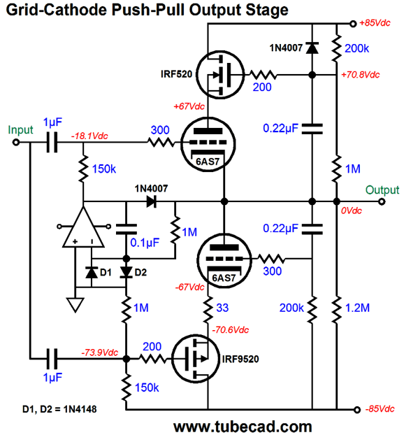
Note how the -30Vdc power-supply rail is derived from the -85Vdc power-supply rail. Now, let's return to the complete output stage, but with all the needed extras.
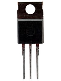
Diodes, D1 & D2, are there to protect the OpAmp's inverting input from over voltages. The 1.2M resistor cancels the upward pull from the 200k and 1M resistors in series, keeping the output ground centered, even with the 6AS7 missing from its socket. The IRF520 and IRF9520 MOSFETs are TO-220 devices with 60W and 100V ratings. In addition, they cost less than $1 each. More importantly, they present a fairly low input capacitance.
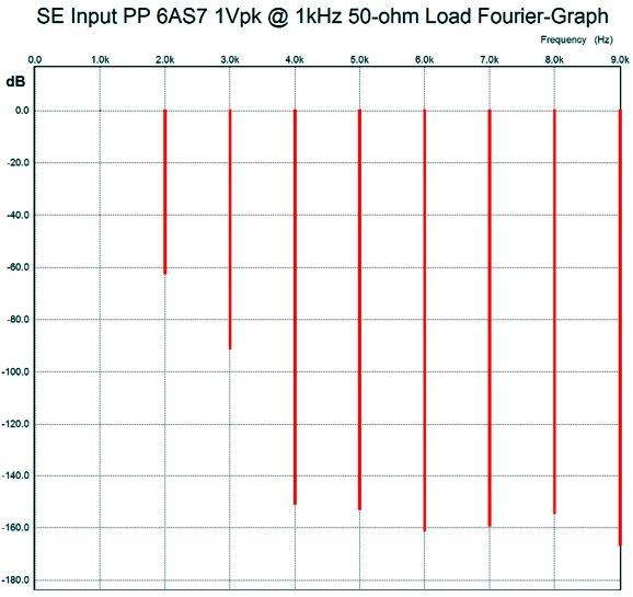
What has been missing from this post is an explanation of what this new circuit could be used for. Well, a power amplifier is only required when we must delivered power into a load impedance. One possible load is headphones, as the new planar headphones present both low impedance and low efficiency. The 6AS7 running in this circuit with +/-85Vdc power-supply rails, will pass over 200mA of current. This amount of current against a 50-ohm load will develop a peak voltage swing of 10V, which equals 1W of output power, or as a headphone-amplifier company would prefer to advertise it, 1,000mW. Note that in this design example, class-A operation is achieved with a 50-ohm load and 1W of output. If a 16-ohm load were used instead, we could only get 1W of class-AB power, not class-A power, and we would see positive grid voltages. How well does the Grid-Cathode Push-Pull output stage work? Well, into a 50-ohm load and at 1kHz with 1Vpk of output, the following SPICE generated Fourier graph results.
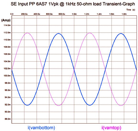
Sweet. Very Sweet. Very single-ended in quality. How good is the balance between top and bottom triodes in terms of current conduction?
If a 32-ohm cathode resistor could be bought, the balance would be dang close to perfect.
The Missing Step
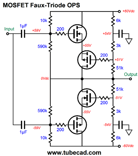
But an hour or two later, I felt a nagging reminder in the form of the following topology, which I had come up with decades ago in an attempt to create a faux triode out of solid-state devices.
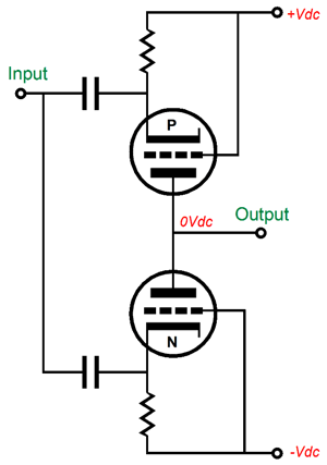
Effectively, this output stage consists of two solid-state faux triodes, each exhibiting both an amplification factor and a plate resistance. But unlike real vacuum-based triodes, one of the faux triodes is a P-version, which could never exist in a vacuum triode, as electrons must flow from negative to positive potentials. (Fifty to eighty years ago many tried to make P-version of the triode; in vain.) If such a P-version of the triode existed, we could make the following circuit, which is functionally the same as the MOSFET version shown above.
Note how the cathodes, not the grids, are driven by the input signal. Neither P nor N triode functions as cathode follower, but grounded-cathode amplifiers; so voltage gain results, as long as the load impedance is high enough. Returning to the MOSFET version shown above, the voltage divider string of resistors, 3k and 51k, seem to imply a mu of (51 + 3) / 3 or 18, but in SPICE simulations, the above output stage only achieved a voltage gain of 8. Yes, this output stage provides amplification. At the same time if offers “plate” resistance, as an increase in power-supply rail voltages will result in greater current flow. Now, getting voltage gain from an output stage is a big feature, as it means that the input and driver stage do not have to swing big output voltages, which in turn means that we can easily provide regulated power-supply rails to these stages.
I couldn’t find my SPICE file for the complete solid-state faux-triode power amplifier. But imagine if an OpAmp running off of regulated +/-12V power-supply rails were used to drive this output stage. Returning to the Grid-Cathode output stage, as I looked over the schematic of this MOSFET-based faux-triode output stage, I saw how I could replace two MOSFETs with actual triodes. Then I realized that would not be enough, so I sought to fix the remaining problems. The mind works in mysterious ways—well, at least mine does.
*Formula
Well, the formula I showed previously, Rk = rp/mu - rp/(mu +1), was derived from the following formula: (mu + 1) / [rp + (mu + 1)Rk] = mu/rp The idea behind the formula is simple: we need to know what value of Rk would result in a cathode gm diminished to same value as the grid gm. The left side of the equal sign is the bottom triode with a cathode resistor, an unbypassed cathode resistor. The right side of the equal sign is the top triode with no cathode resistor (or with a bypassed cathode resistor). We then solve for Rk and get: Rk = rp/mu - rp/(mu +1)
Next Time
User Guides for GlassWare Software Since I am still getting e-mail asking how to buy these GlassWare software programs:
For those of you who still have old computers running Windows XP (32-bit) or any other Windows 32-bit OS, I have setup the download availability of my old old standards: Tube CAD, SE Amp CAD, and Audio Gadgets. The downloads are at the GlassWare-Yahoo store and the price is only $9.95 for each program. http://glass-ware.stores.yahoo.net/adsoffromgla.html So many have asked that I had to do it. WARNING: THESE THREE PROGRAMS WILL NOT RUN UNDER VISTA 64-Bit or WINDOWS 7 & 8 or any other 64-bit OS. One day, I do plan on remaking all of these programs into 64-bit versions, but it will be a huge ordeal, as programming requires vast chunks of noise-free time, something very rare with children running about. Ideally, I would love to come out with versions that run on iPads and Android-OS tablets.
//JRB |
Kit User Guide PDFs
And
High-quality, double-sided, extra thick, 2-oz traces, plated-through holes, dual sets of resistor pads and pads for two coupling capacitors. Stereo and mono, octal and 9-pin printed circuit boards available.
Designed by John Broskie & Made in USA Aikido PCBs for as little as $24 http://glass-ware.stores.yahoo.net/
The Tube CAD Journal's first companion program, TCJ Filter Design lets you design a filter or crossover (passive, OpAmp or tube) without having to check out thick textbooks from the library and without having to breakout the scientific calculator. This program's goal is to provide a quick and easy display not only of the frequency response, but also of the resistor and capacitor values for a passive and active filters and crossovers. TCJ Filter Design is easy to use, but not lightweight, holding over 60 different filter topologies and up to four filter alignments: While the program's main concern is active filters, solid-state and tube, it also does passive filters. In fact, it can be used to calculate passive crossovers for use with speakers by entering 8 ohms as the terminating resistance. Click on the image below to see the full screen capture. Tube crossovers are a major part of this program; both buffered and un-buffered tube based filters along with mono-polar and bipolar power supply topologies are covered. Available on a CD-ROM and a downloadable version (4 Megabytes). |
||
| www.tubecad.com Copyright © 1999-2016 GlassWare All Rights Reserved |
