| John Broskie's Guide to Tube Circuit Analysis & Design |
31 May 2016
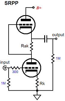
Variations on the Theme of the White Cathode Follower Should all conventional cathode followers be replaced by White cathode followers? No. often we do not need to deliver real power into a load or require a lower output impedance. At these times, the added expense and complexity is not justified. The White cathode follower belongs to the family of push-pull, class-A circuits that includes the SRPP and SRCFPP, as all three circuits use a current-sense resistor to create the needed anti-phase signal for push-pull operation.
In other words, since these three circuits see an unbalanced input signal, the second triode's grid requires its own input signal, a signal which is an inverted copy of the signal that the input triode sees.
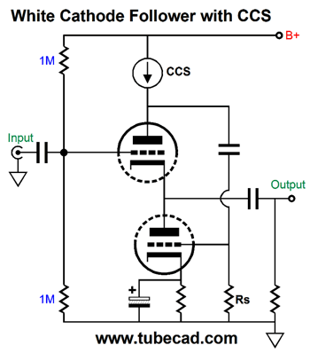
The voltage drop across a resistor depends on the amount of current flowing through the resistor. If the external load impedance presents a high resistance, then the AC current flowing through the current-sense resistor will be small; if the resistance is low, on the other hand, the AC current flow will be big. Ideally, we want both triodes to work equally into the load; which means that for any given load impedance, there is an optimal value for the current-sense resistor. This means that the White cathode follower and SRPP and SRCFPP are not universal push-pull amplifiers, as they are all load dependent. The formula for the optimal White cathode follower sense resistor value is Rs = (rp + 2Rload) / mu where rp is the triode's plate resistance and mu is the triode's amplification factor. Mind you, this is the formula for the maximum power delivery. If power is not as important as is a low output impedance, we can use a larger Rs resistor. In fact, if we desire the lowest possible output impedance, then we would replace the current-sense resistor with a constant-current source.
The resulting output impedance is equal to the plate resistance divided by the mu². For example, with a 6DJ8, we can get an output impedance of only 3 ohms. Of course, nothing comes for free, and the price we pay is that we lose the push-pull operation, as the top triode must conduct the same amount of current as the constant-current source pours forth. In other words, the maximum peak current swing into the load will equal the idle current. Another variation would be to use a signal transformer with a 1:1 winding ratio, as shown below.
Transformers are current-sensitive, passive devices. Ideally, the transformer's primary will displace no DC voltage. (Of course, real transformers are made up from real wire wire, all of which offer some resistance.) Note how the value for resistor Rs remains the same as before. With a 1:1 coupling transformer, the Rs resistor is effectively, in AC term, in series with the top triode's plate and the B+ connection. Two problems arise, however, with using a coupling transformer. The first is that the transformer's primary must sustain a steady DC current flow at idle; the second is that the high-quality coupling transformers are both rare and expensive. Is there any other way to relay the AC signal developed across the current-sense resistor? Indeed there is.
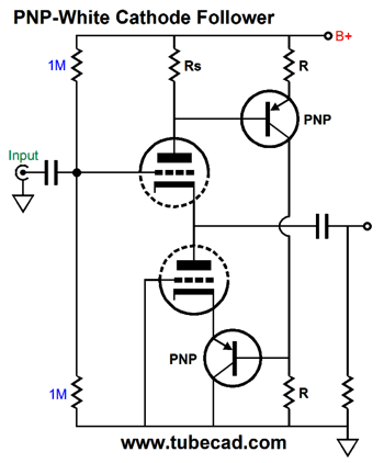
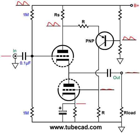
PNP-White Cathode Follower
Yes, we have relayed the signal down, but the phase got inverted in the process, returning to the same phase as the input signal—which is exactly what the bottom triode's grid does not need, as it needs to see an anti-phase signal. The cathode, on the other hand, works in the opposite current phase of the grid. By adding an additional PNP transistor and grounding the grid allows us to achieve push-pull operation from the two triodes.
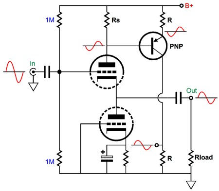
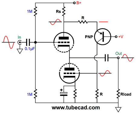
If the voltage drop across resistor Rs increase, so, too, will the voltage drop across both resistors labeled "R." Of course, many will find this circuit holds two transistors too many, preferring no transistors. Sure, to each his own. Some fear capacitors, however, more than they fear transistors; thus, they would find the above topology particularly fine, as it also eliminates the cathode-resistor and its bypass capacitor, which is invariably an electrolytic type. Is there any way to use fewer transistors, i. e. just one transistor? Indeed there is. The following circuit use only one PNP transistor to relay the AC signal developed across the current-sense resistor to the bottom triode's grid, with the signal phase retained.
As the voltage drop across resistor Rs increases, the voltage drop across the top R resistor decreases, causing the voltage drop across the bottom R resistor to decrease as well and by the same amount. What would be the optimal value for resistor Rs in this topology? Well, note that resistor Rs is effectively in parallel with the top R resistor. (We should also note that the PNP transistor imposes a slight loss of gain.) In other words, the formula is a good starting point, but expect some tweaking of values to be needed. In addition, we must acknowledge that the bottom R resistor sees a DC offset due to the steady current flow through it at idle. This means that the bottom triode's cathode resistor must be larger in value than what you might otherwise expect. Assuming that we can fiddle with the values enough to get an optimal balance between top and bottom triodes, so the external load impedance sees the greatest, cleanest power delivery, how good would the resulting PSRR be? With a conventional cathode follower, the PSRR is quite good, as the amount of power-supply noise that leaks from the output is usually equal to or less than 1/mu. (Somewhat paradoxically, replacing the cathode follower's cathode resistor with a constant-current source increases, not decreases, the amount of power-supply noise at its output.) With a White cathode follower, the PSRR is usually worse, as the current-sense resistor terminates into the B+ connection, so this resistor not only develops an anti-phase signal, it provides a ready connection to the power-supply noise, which then gets relayed to the bottom triode's grid by the internal coupling capacitor.
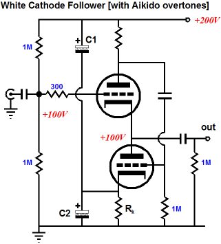
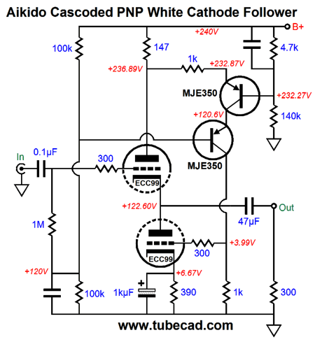
I have presented my own Aikido workaround to the poor PSRR in blog post 104, as shown below.
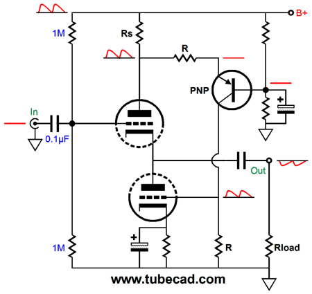
This workaround might work well with the PNP White cathode follower, but I wanted to see how bad it was without the Aikido fix. I set up a SPICE simulation of the following circuit, with all the part values chosen to establish optimal push-pull operation into a 300-ohm load.
The first thing that I noticed was that the power-supply noise was inverted at the output. Bingo! as we Americans are wont to exclaim. The inversion of the power-supply noise implies that with some clever alterations we could achieve a power-supply-noise null at the output. My first thought was: What would happen if I removed the capacitor that attaches to the PNP transistor's base? The answer was that the PSRR improved substantially; indeed, it exceeded what the conventional cathode follower would deliver with the same triode.
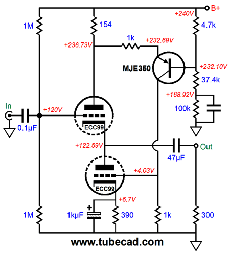
Of course, I didn't stop there; instead, I tweaked values until I achieved an even deeper power-supply-noise null at the output. Here is what worked best in SPICE simulations.
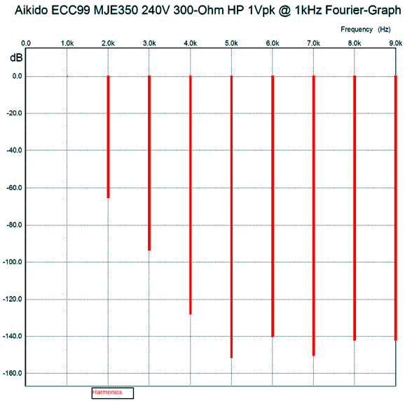
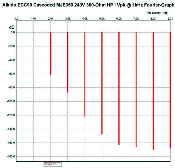
(In order to make for less clutter, I left out of the schematic the absolutely essential grid-stopper resistors. Use them in reality.) The PSRR was better than -60dB and the distortion was low (about 0.1%), as revealed by the following Fourier graph of the harmonics.
The output impedance came in at a tad less than 50 ohms. Not bad. One worry might be that the PNP transistor will accidentally see too much voltage, say at start up when the tube is cold and not conducting, so the B+ voltage is not yet dragged down by the high idle current.
The highest-voltage readily available PNP transistor that I know of is the MJE5852G, which comes in a TO-220 package. It is an 8A, 400V, 80W transistor that cost about $3 each. Alternatively, we could cascode two PNP transistors.
Note the change in part values and the capacitor shunting the 4.7k resistor at the B+ connection. The PSRR worsened a tad, coming in at -47dB, rather than the previous -60dB. Still, not bad at all. Most interestingly, the SPICE simulations revealed both higher and lower harmonics.
The second and third harmonics are higher than before, but all the others are lower. I am sure that my ears would prefer this harmonic structure, as it looks quite single-ended in flavor. Cool.
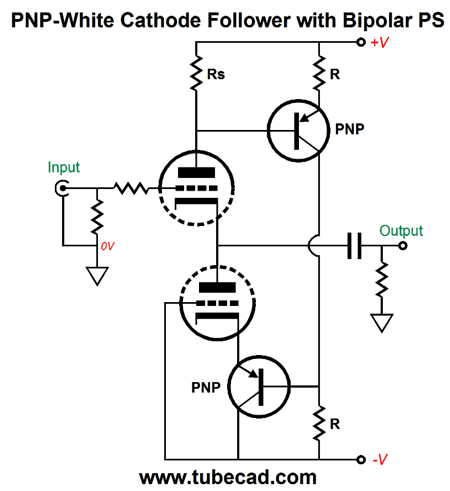
PNP-White Cathode Follower with Bipolar Power Supply Let's examine the version that uses a PNP transistor in place of the cathode resistor. The circuit below does require an input capacitor, but still needs a coupling capacitor at its output. One advantage to this arrangement is that since the top triode's cathode is only a few volts above ground level, we can get away with using a non-polarized electrolytic capacitor. The great benefit to using a non-polarized electrolytic capacitor, particularly those from Panasonic, offer much lower distortion compared to a polarized electrolytic capacitor. See post number 232.
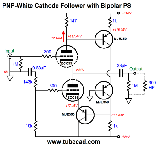
But, John, wouldn't a film capacitor be even better? Perhaps, but I doubt that you can readily find a 330µF film capacitor, whereas a non-polarized electrolytic capacitor in that value is easy to find, which is something you need to do if your plan on driving 32-ohm headphones. In addition, we can always bypass the non-polarized electrolytic capacitor with a smaller-valued film capacitor, say a 30µF and a 0.33µF. The above schematic reveals the the basic flavor. Fleshing the design out brings us to the following design.
Note how the the two PNP transistors are cascoded and how the bottom triode's grid is no longer terminated into the negative power-supply rail. Instead, the bottom triode gets the Aikido treatment, wherein a sampling of the power-supply noise is presented to the the bottom triode's grid, resulting in a null in power-supply noise at the output. (Actually, the grid sees slightly less of the power-supply noise than the cathode does, so effectively, the bottom triode's grid sees a positive sampling of power-supply noise.) In SPICE simulations, the results were comparable to those achieved before.
Next Time
User Guides for GlassWare Software Since I am still getting e-mail asking how to buy these GlassWare software programs:
For those of you who still have old computers running Windows XP (32-bit) or any other Windows 32-bit OS, I have setup the download availability of my old old standards: Tube CAD, SE Amp CAD, and Audio Gadgets. The downloads are at the GlassWare-Yahoo store and the price is only $9.95 for each program. http://glass-ware.stores.yahoo.net/adsoffromgla.html So many have asked that I had to do it. WARNING: THESE THREE PROGRAMS WILL NOT RUN UNDER VISTA 64-Bit or WINDOWS 7 & 8 or any other 64-bit OS. One day, I do plan on remaking all of these programs into 64-bit versions, but it will be a huge ordeal, as programming requires vast chunks of noise-free time, something very rare with children running about. Ideally, I would love to come out with versions that run on iPads and Android-OS tablets.
//JRB |
Kit User Guide PDFs
And
High-quality, double-sided, extra thick, 2-oz traces, plated-through holes, dual sets of resistor pads and pads for two coupling capacitors. Stereo and mono, octal and 9-pin printed circuit boards available.
Designed by John Broskie & Made in USA Aikido PCBs for as little as $24 http://glass-ware.stores.yahoo.net/
The Tube CAD Journal's first companion program, TCJ Filter Design lets you design a filter or crossover (passive, OpAmp or tube) without having to check out thick textbooks from the library and without having to breakout the scientific calculator. This program's goal is to provide a quick and easy display not only of the frequency response, but also of the resistor and capacitor values for a passive and active filters and crossovers. TCJ Filter Design is easy to use, but not lightweight, holding over 60 different filter topologies and up to four filter alignments: While the program's main concern is active filters, solid-state and tube, it also does passive filters. In fact, it can be used to calculate passive crossovers for use with speakers by entering 8 ohms as the terminating resistance. Click on the image below to see the full screen capture.
Tube crossovers are a major part of this program; both buffered and un-buffered tube based filters along with mono-polar and bipolar power supply topologies are covered. Available on a CD-ROM and a downloadable version (4 Megabytes). |
||


| www.tubecad.com Copyright © 1999-2016 GlassWare All Rights Reserved |