| John Broskie's Guide to Tube Circuit Analysis & Design |
06 July 2016
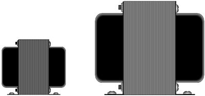
Fine Tuning Constant Power Second, excessive plate dissipation is not the only limit we strive to avoid, as a single-ended output transformer’s maximum DC idle current must be respected and never exceeded. Unlike a push-pull output transformer, which cannot tolerate a continuous DC current flow through its primary, a single-ended output transformer's iron core holds an air-gap, which allows the core to withstand a sustained magnetizing DC current flow through the primary. If this limit is exceeded for a prolong period, the core will saturate, resulting in gross distortion. It is best to play it conservative here, as I have seen a few single-ended output transformers whose specifications were more based on wishful thinking than actual measurement.
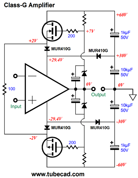
For example, I have seen a single-ended output transformer advertised as being able to deliver 25W, yet the transformer’s specifications state a maximum idle current of 100mA and primary impedance of 3k. Doing the math, reveals that the transformer’s maker could not do the math, as (0.1A² x 3,000) / 2 = 15W, not 25W; or go the other way, 0.1A against 3k equals 300Vpk, which squared equals 90,000, which divided by twice the primary impedance (i.e. 6k) equals 15W. Why the discrepancy? Two possibilities come to mind that avoid the charge of bald duplicity (i.e. lying): the maker, who had hitherto been making only push-pull output transformers and who only recently jumped on the single-ended bandwagon, thought this single-ended transformer looked as big as a 25W push-pull transformer. Another possibility is that the transformer maker is not using average or RMS current and voltage measurements, so he is specifying 25 peak watts, which means that it can only put out 12.5 average watts. Well, at least he was not using instantaneous peak watts, which might be as high as 50W. For those not as old as I, back in the 1960s, when transistor amplifiers just appeared, you would see a cheesy, 10W, solid-state amplifier advertised as putting out 40 instantaneous-peak-watts. Magic? No, the thinking was that by using a wimpy power supply, whose rail voltage was higher than required for 10W of output, but whose sustained current delivery could only produce 10W of output for prolonged periods, you could get huge instantaneous peak watts, say for half a second or so. Was this practice dishonest? Yes. Nonetheless, I will swim against the stream here and say that it might have some merit. It all depends on the kind of music you listen to. Some music is intrinsically dynamic, which means that it exhibits big contrasts between quiet passages and occasional loud bursts of sound. Even within passages, on a scope it looks more like speech than a broken function generator's output. With the exception of organ music, most classical music falls in the wide dynamics category, as does most acoustic music. Most modern popular-music recordings, however, are both musically thick and heavily electronically compressed, which is problematic, as the music seldom, if ever, goes quiet, MUCH LIKE A TEXT WRITTEN IN ALL CAPS WITH EACH SENTENCE ENDING IN MANY!!!!! Grindingly consistent, relentlessly thumping, ceaselessly buzz-sawing away at our ears and, by extension, the spongy wet gray matter in between our ears, the unrelentingly uniformity of high SPL means that this loud sonic wallpaper precludes the possible advantage of huge instantaneous peak watts. Okay, I admit it, that was a slander, a baseless slander, as plenty of music is being performed and recorded today that does not fall into the category of sonic sludge. Sadly, little of this interesting music makes the Top 10 list. Recently, I made a sonic survey of the Grammy nominated music of 2013, 2014, and 2015. Mostly grim. The exceptions were just that: exceptions. At a party last month, a young man in his early twenties asked me what Jazz was! My answer was that it was a fusion of African and European music, that it was an amazing wedding of improvisation to cohesion, the fantastic bonding of freedom with responsibility, that it was—even more so than blues, blue grass, country, rap, and rock 'n roll—the archetypal American music, and that it was America's greatest artistic gift to the world. His next question was: What happened to Jazz? My answer was that it died, having starved to death, as Jazz consumes popular music, digesting it, and creating new musical expressions out of the old music, but popular top-10 music holds too little meat, consisting mostly of bone, gristle, and fat, so Jazz can no longer transform the preposterous into the profound, the silly into the sublime, as the heavily-processed, tuneless and melody-free hits of today cannot sustain Jazz. He then asked, What music works best for Jazz to eat or transform? My answer was that the Great American Songbook worked supremely well, but any music whose melody can be whistled or hummed is suitable, for example, most of the Beatle's catalog of songs. Returning to circuitry, with suitable music, however, a nominally 36W amplifier that could produce brief peak bursts of 200W would be quite desirable. How could we design such a beast? Class-G, wherein two sets of power-supply rails are used, say +/-30Vdc and +/-60Vdc, with robust lower-voltage rails and flimsy high-voltage rails.
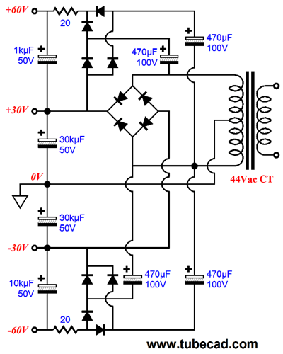
The star of the above show is the 100-ohm resistor. How so? It prevents switching induced oscillations. (I would experiment with shunting it with an RC network.) The output devices would idle under the 58.8Vdc differential, but when called upon, the higher rail voltages would kick in, allowing brief bursts of huge watts before the higher rail voltages sagged and collapsed, which would be a feature, not a bug, as we do not want to burn up the output devices under prolonged high-wattage output.
The idea behind this power supply is that +/-60V rails would prove weak under prolonged demand. Perhaps, in spite of my efforts, that above circuit may still be too robust and smaller-valued capacitors would be needed.
Returning to constant-power circuits, if a single-ended output transformer is rated for no more than 100mA, what should we set the idle current to? In general, my rule is to fall short by at least 10%, thus 90mA would be safe. With a constant-power output stage, something like 85% would prove safer. Here is why: constant-power works by varying the idle current in response to a change in B+ voltage; if the voltage climbs, the idle current is cut back, which moves us away from the transformer’s DC current limit; if the voltage falls, the idle is raised to maintain a constant plate dissipation, which moves us closer to the current limit; indeed, it may bring past the limit.
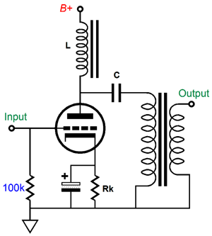
What about parallel-feed output stages? In the parallel-feed arrangement, the output transformer is capacitor coupled, so it sees no DC current flow. The inductor that goes between the plate and B+ connection does see a sustained DC current flow, and it, too, can saturate with too much idle current. (If you are indeed clever, you can build in a current limit, so even if the B+ falls excessively, the idle current would reach a stop value. I will try to include an example circuit.)
In a solid-state-based, single-ended output stage, we seldom encounter an output device current limit, as most power MOSFETs and transistors are rated for gobs of current. No, the limits we usually encounter are the solid-state device’s junction and heatsink temperature. If the junction temperature gets too hot, the device gives up the ghost, sometimes in a dramatic fashion, with the die exploding off the device. If nothing else, should the heatsink temperature go above 60C, you could end up with burnt fingers. Of course, a lot depends on how much wall-voltage variation we can expect to encounter. In general, the power company worries much more about delivering too much voltage to your house than it is about providing too little, as too little seldom results in damage to electric devices, such as computers, toasters, TVs, and vacuum cleaners. I remember a friend living on the fifth floor of an old Victorian apartment building in San Francisco whose wall voltage came in at a meager 105Vac, due to the losses in the thin wiring used. At the same time, I lived 50 miles south of him and wall voltage ran a rock-steady 123Vac; the target voltage was 117Vac. My wall voltage ran 5% hot, while his ran 11% low. A reasonable expectation might be +/-10% variation about the target voltage. (By the way, wall voltage in the USA has steadily risen with time, as it started out at about 110Vac.) Interestingly enough, in Brazil, they run multiple wall voltages, depending on where you live; in fact, some big hotels run a different wall voltage from the rest of the city. (I used to know this Brazilian expat, who constantly went on and on about how Brazil was the greatest country on Earth. His arguments would have been a wee bit more convincing, if he had not fled the people's paradise below the equator to come live in what he believed to be the worst country in the world.)
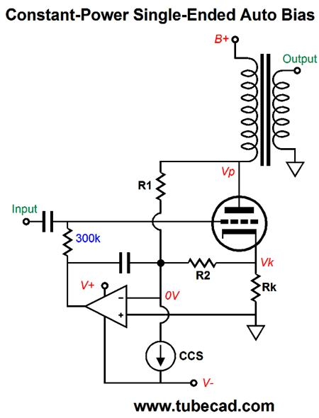
Constant-Power Negative-Grid Bias Just as before, the required steps are to both measure the current flow through the output tube and the plate voltage, and then compare these two against a voltage reference and make compensating adjustments to the grid voltage. If the plate voltage goes up, then the idle current must go down. If the plate voltage falls, the idle current must rise. The following schematic show the basic idea.
Resistors, R1 & R2, function as voltage-to-current converters. The bigger the voltage drop across a resistor, the greater the current flow through the resistor. Because the two resistors meet at the OpAmp’s inverting input and the constant-current source, which strives to maintain a fixed current flow, an increase in current flow through one resistor must be cancelled by a decrease in flow through the other resistor, so a constant amount of current can flow into the constant-current source; atthe same time, the OpAmp’s inverting input remains stuck at 0V. This cancellation can only obtain if the current flowing through both resistors is the same. In other words, the change in plate voltage over R1 must equal the change in cathode voltage over R2. For example, if resistor R1 sees 10% more voltage across its leads, then resistor R2 must see 10% less voltage across its leads. Thus, working out the resistor values is easy, as Vp/R1 = Vk/R2, so the ratio of Vp/Vk is the same ratio as R1/R2.
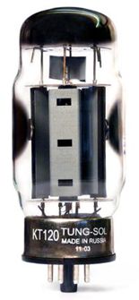
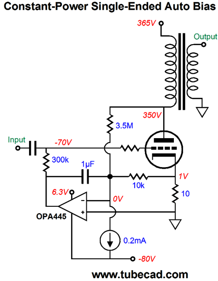
In this example, R1 is 3.5M, while R2 is 10k. Since they do not make 1%, 3.5M resistors, we can use 2M and 1.5M resistors in series. The OpAmp needs a positive power-supply rail voltage slightly higher than ground potential, say 5Vdc or 6.3Vdc, which can double as a heater power supply. (300B heater/cathode voltage is 5V, while a KT88 or KT120 heater element’s voltage is 6.3V.) The 1µF capacitor may seem high in value, but it isn’t, considering the relatively low-valued 10k resistor.
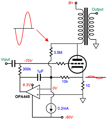
Note that the plate and cathode move in anti-phase. As the plate swings down, due to the triode conducting more current, the cathode voltage climbs, as an increased current flow through the cathode resistor creates a larger voltage drop. Do these two movements cancel at the OpAmp’s inverting input in the constant-power circuit? No. They would come close with a solid-state output device, such as a high-voltage MOSFET, but with triodes not a chance, as the plate can never swing down anywhere close to ground potential, due to positive-grid limitation and its high plate resistance. The cathode resistor, on the other hand, can see its voltage drop double and then disappear altogether. In contrast, the 3.5M resistor can never see its voltage drop double and then fall to zero. Still, there is some degree of AC signal cancellation, which helps the 1µF capacitor erase the AC signals. The OpAmp is special high-voltage design, the OPA445, which sells for a bit over $12 each. Okay, what happens if TI ceases production of this OpAmp next year or you think that $12 is a ridiculous amount to pay for an OpAmp that is not directly in the signal path? Well, we could use a lower-voltage device.
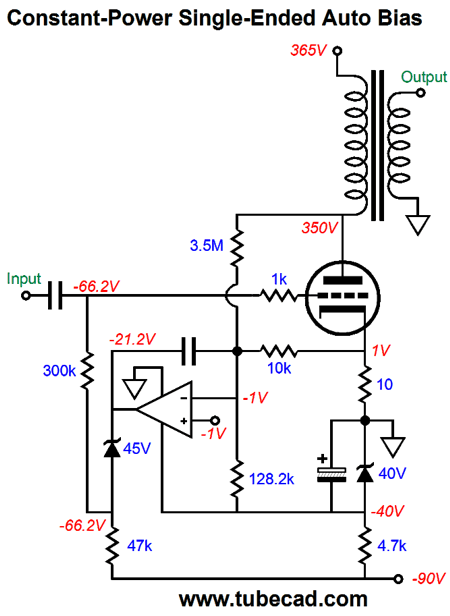
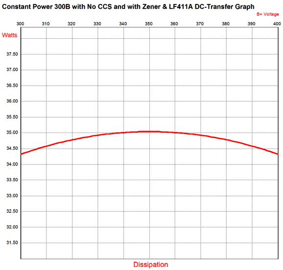
Note that the OpAmp's positive power-supply pin is now grounded. Also note that its non-inverting input is no longer grounded, but attaches to a -1V reference voltage instead. And, finally, note that no constant-current source [CCS] is used. In its place we find a 128.2k resistor. Do not worry about no one making a 128.2k resistor; instead, think about why it is there. First, the resistor sees a voltage drop of 39V, which implies a current flow of 39V/128.2k or 3mA. Since the OpAmp's inverting input presents a very low input impedance, the 128.2k resistor sees a constant 39V, so it must draw a constant 3mA of current and it must be functionally equivalent to a 3mA CCS. Magic, cheap magic at that. The 40V zener establishes the OpAmp's power-supply voltage and the 45V zener relays the OpAmp's output voltage down to where it is needed. If you were wondering why the 10k resistor was used in place of a 20K resistor, I am proud of you. What is going on here is that although 2V develops across the 10k resistor, we must use the 10k value, as we want it respond in the exact same fashion as it had in the previous example, with the 1V voltage drop. This way, a 10% reduction in the plate voltage will be cancelled by a 10% increase in the voltage across the cathode resistor. A 20k resistor could not alter in current draw sufficiently. So, how well does the above circuit work? Here is the SPICE simulations graph of a plate voltage shift of 100V.
Well, I guess the title gives away which output tube and OpAmp were used. The results are excellent, as the +/-50V shift in plate voltage results in only a 2% shift in plate dissipation. To be honest, I do not much like the 45V zener. One workaround would be to to add a PNP transistor.
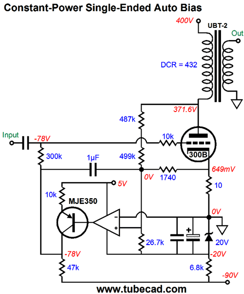
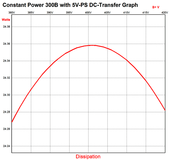
This design example uses a UBT-2 output transformer from One Electron. It's primary presents an impedance of 4,800 ohms and it offers 16, 8, 4 ohms taps on its secondary. Its primary holds a DCR of 432 ohms. From the One Electron website, we see a design listing of 400V and 65mA for the single 300B output tube. The OpAmp's positive power-supply pin connects to a 5Vdc power-supply rail, while its negative pin attaches to the bottom of the 20V zener, so the OpAMp sees a power-supply differential voltage of 25V. THe MJE350 is a high-voltage (300V) PNP transistor. because this transistor inverts the phase at its collector, the OpAmps inputs must be flipped, so the inverting input becomes the non-inverting one; the non-inverting input, the inverting input. How well does this circuit work in SPICE? Here is the graph.
It misses the target of 350V, due the limitations imposed by limited values of 1% resistor. Dang fine.
Constant-power Unity-Gain Power Buffer 2
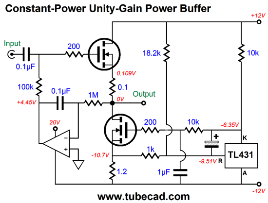
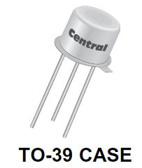
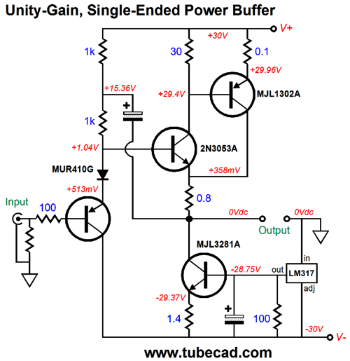
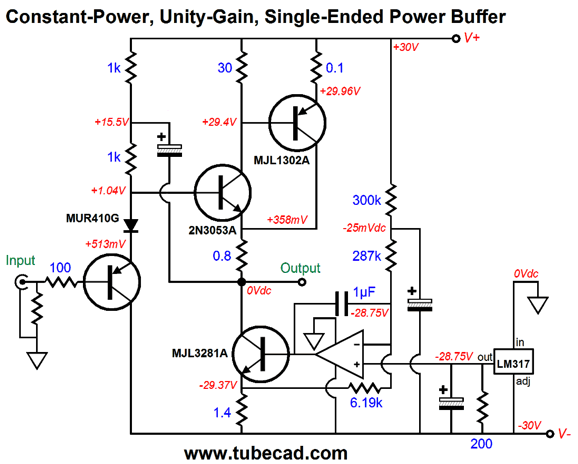
Well, this circuit prompted me to go hunting through my SPICE files for other class-A power-buffer designs that could be updated to constant-power. The following design was inspired by a reader revealing to me that the 2N3053 was an excellent NPN transistor. I bought a few and I was well pleased with the results (besides, I love the TO-39 case, as it looks great with one of those black circular heatsinks).
My idea was to design a unity-gain, single-ended power buffer that could drive the new planar headphones. The idea is to use the 2N3053 as the brains that controls the brawn of the MJL1302A PNP transistor, as the compund arragement ceates a negative feedback loop that lowers the both the distortion and output impedance (Zo).
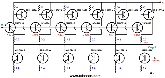
In the original schematic, the power-supply rails were a low +/-12V, not +/-30V shown now. The idle current is 445mA, which would be plenty for any headphones, but far too meager for any speaker. True enough. But what if we use five of these stages in parallel? This would bump the idle current up to a rich 2.2A, which could deliver 16Vpk into 8-ohm loads, resulting in 16W of output power. No doubt that a few readers are wondering why the +/-30V power-supply rails were used when lower +/-20V rails would suffice? My thinking was that such a unity-gain, single-ended power buffer would make an excellent impedance-multiplier circuit (IMC), whose output would be 24Vpk, not 16Vpk, resulting in 36W of output, the missing 1A being delivered by the tube amplifier driving the IMC.
Perhaps it would best to go and re-read post number 283 first, as it explains the design concept well.
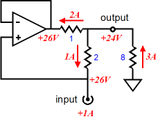
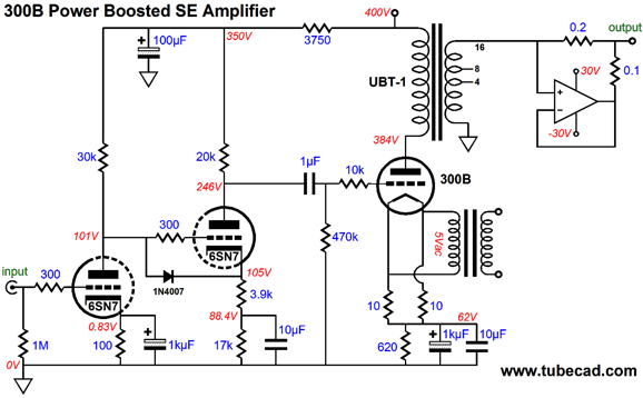
The UBT-1 singe-ended output transformer offers a truly low winding ratio between primary and secondary; the primary to the entire secondary ratio is 10:1, so the impedance ratio is 100:1, while the voltage ratio is 10:1 and the current ratio is 1:10. This means if the 300B's idle current is 100mA, the output current will be 1A.
Since we are enjoying all the wonderful, ear-pleasing single-ended glory of the 300B amplifier, why spoil it by using a class-AB IMC? Indeed, why not be consistent and use a single-ended IMC? Interestingly enough, phasing between the tube amplifier and the IMC will be important, as both exhibit a 2nd harmonic distortion characteristic, so if the two cascade in phase, the 2nd harmonic will ripen even further; cascade in anti-phase, lessen, possibly even cancel. Adding the constant-power function is easy enough, as we need only add an OpAmp and a few resistors and capacitors.
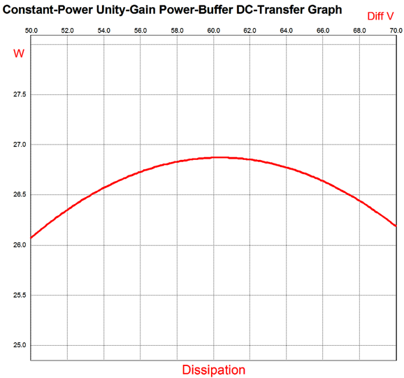
The LM317 is used a cheap but good voltage reference that puts out 1.25V. The 300k and 287K ressitors and the unmarked capacitor, shield the OpAmp's inverting input from the B+ ripple. The OpAmp should be a rail-to-rail design, such as the AD823, whose input voltage can descend below its negative power-supply voltage. How well does the constant-power feature work?
The X-axis shows the the total differential power supply voltage. The next step would be to use five output-stage cluster in parallel.
The MJL1302A and MJL3281A are complementary power transistors in the TO-264-3 (TO-3BPL) package. They cost about $3.50 each from Digikey. Each transistor will dissipate about 13W, so the complete output stage will dissipate 130W. Think big heatsink.
As for the input, we can use the same DC servo circuit shown before.
With this DC servo in place, we can forgo the use of the MUR410G rectifier, as the servo will adjust the voltage automatically. After putting it all together, the 300B-based single-ended amplifier would see an external load impedance of 24 ohms, which the UBT-1 transformer would reflect to the 300B's plate as a 2400-ohm load. My quick mental-math calculations reveal that a 400V B+ voltage would suffice. (Do not try this at home.) The 300B would idle at 100mA and dissipate 38W, which is crazy hot. Two 300B output tubes in parallel could run with idle currents of 7omA each, resulting in only 27W of dissipation. In addition, the two 300Bs would yield less distortion and half the output impedance. Or, a single KT120, triode-connected, would work.
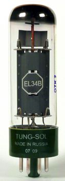
Actually two EL34 tubes would be my choice.
Why don't I show the entire schematic? Mostly because I have run out of time. Unless you have actually drawn big schematics, you cannot imagine how long it takes. (I used to know a highly-sought-after tech writer who charged $2,500 for truly large schematics and $1,000 single-page ones. I am sooo in the wrong business. But then, maybe not. Maybe, much like radiology being outsourced to India, huge schematic drawings might only cost $100 these days.) Besides, if you cannot assemble the entire circuit on paper, you shouldn't be thinking about building it in reality ;)
//JRB
User Guides for GlassWare Software Since I am still getting e-mail asking how to buy these GlassWare software programs:
For those of you who still have old computers running Windows XP (32-bit) or any other Windows 32-bit OS, I have setup the download availability of my old old standards: Tube CAD, SE Amp CAD, and Audio Gadgets. The downloads are at the GlassWare-Yahoo store and the price is only $9.95 for each program. http://glass-ware.stores.yahoo.net/adsoffromgla.html So many have asked that I had to do it. WARNING: THESE THREE PROGRAMS WILL NOT RUN UNDER VISTA 64-Bit or WINDOWS 7 & 8 or any other 64-bit OS. One day, I do plan on remaking all of these programs into 64-bit versions, but it will be a huge ordeal, as programming requires vast chunks of noise-free time, something very rare with children running about. Ideally, I would love to come out with versions that run on iPads and Android-OS tablets.
//JRB |
Kit User Guide PDFs
And
High-quality, double-sided, extra thick, 2-oz traces, plated-through holes, dual sets of resistor pads and pads for two coupling capacitors. Stereo and mono, octal and 9-pin printed circuit boards available.
Designed by John Broskie & Made in USA Aikido PCBs for as little as $24 http://glass-ware.stores.yahoo.net/
The Tube CAD Journal's first companion program, TCJ Filter Design lets you design a filter or crossover (passive, OpAmp or tube) without having to check out thick textbooks from the library and without having to breakout the scientific calculator. This program's goal is to provide a quick and easy display not only of the frequency response, but also of the resistor and capacitor values for a passive and active filters and crossovers. TCJ Filter Design is easy to use, but not lightweight, holding over 60 different filter topologies and up to four filter alignments: While the program's main concern is active filters, solid-state and tube, it also does passive filters. In fact, it can be used to calculate passive crossovers for use with speakers by entering 8 ohms as the terminating resistance. Click on the image below to see the full screen capture. Tube crossovers are a major part of this program; both buffered and un-buffered tube based filters along with mono-polar and bipolar power supply topologies are covered. Available on a CD-ROM and a downloadable version (4 Megabytes). |
||
| www.tubecad.com Copyright © 1999-2016 GlassWare All Rights Reserved |


.jpg)
 versus