| John Broskie's Guide to Tube Circuit Analysis & Design |
|
29 July 2016
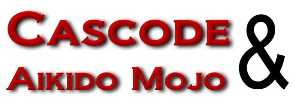
Cascode and Aikido Mojo
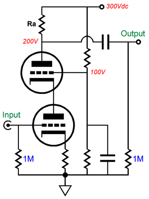
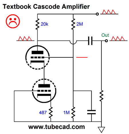
(I have been wanting to redo all the early schematics, but at my back I always hear Time's winged chariot hurrying near.) Here is a generic, textbook cascode example, which looks much like a grounded-cathode amplifier with an extra triode stuck in between the triode's plate and its plate resistor. This may not look as if it could make much of a difference, but it does.
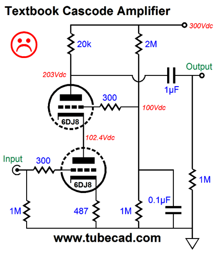
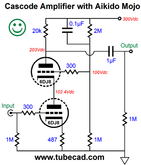
The bottom triode's transconductance is preserved, as the top triode acts like a cathode follower and prevents the bottom triode's plate from moving up and down in response to an input signal; thus no Miller-effect capacitance and no lessening of the bottom triode's transconductance. The top triode then relays the variations in current flow from the bottom triode up to the plate resistor, Ra. Here is a fleshed out cascode circuit, complete with part values and voltages.
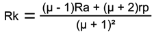
WTF, why the face? as Phil Dunphy would say. Poor PSRR. A very sad face indeed.
The two triodes and the cathode 487-ohm resistor work together to present an impedance of about 660k at the top triode's plate, which then defines a two-resistance voltage divider with the 20k plate resistor. The result is that 97% of the B+ ripple emerges at the cascode's output: a PSRR figure of -0.26dB, i.e. next to nothing. With this design example, a super simple Aikido mojo fix requires no extra parts, only a part shift.
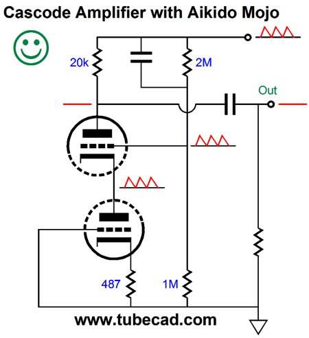
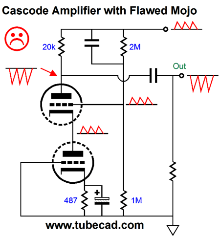
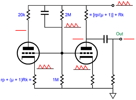
Did you spot the difference? Note where the 0.1µF capacitor is terminated; it isn't ground. By configuring the capacitor this way, all of the B+ noise is relayed to the top triode's grid. Isn't that bad? No. Indeed, no.
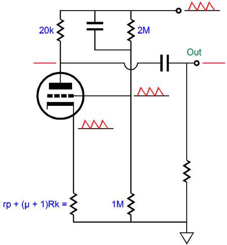
The bottom triode and its cathode resistor combine to present an impedance of about 20k, as the resistance equals rp + (mu + 1)Rk, the total of which is also the plate resistor value. The result is that the power-supply noise presented to the top triode's grid creates a variation in current flow that creates a power-supply-noise null at the output. In other words, as the B+ bounces up, the top triode's plate tugs down, countering the upward pull, creating a null at the output. Still not getting it? Then imagine the bottom triode and its cathode resistor replaced by a single resistance.
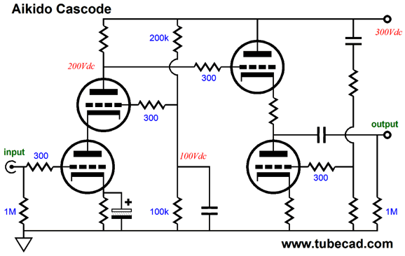
The top triode effectively functions as a grounded-cathode amplifier (or a split-load phase splitter, if you wish). It gain is set to 1, i.e. 0dB. Remember that a grounded-cathode amplifier inverts the phase it sees at its grid at its output. So, 100% of the power-supply noise is presented at the grid and it becomes inverted, but with the same amplitude at its plate; thus, +1 + -1 equals 0. As you might imagine, a formula would come in handy. Here is the formula for the top triode in the cascode circuit acting as grounded-cathode amplifier, its cathode resistor the bottom triode and its actual cathode resistor.
If we set the gain to 1 and solve for Rk, we get the following formula (if I haven't messed up):
This value should get you close. Just close, why not exactly? Unlike a bowling ball's diameter and mass, a triode's rp and mu are not fixed , as these two values vary across plate voltages and currents. In SPICE simulations, this design example using a 6DJ8 and 20k plate and 487 ohm cathode resistors, the PSRR came in below -60db, which is about a thousand times better than the textbook version of the cascode. Thus, even if you only get close, you could easily expect a hundredfold improvement in PSRR. John, John, why are so obsessed with PSRR, particularly when drive and slam and pacing are so much more important? I get this question all the time. The answer is simply that drive and slam and pacing—and any other audio attribute you highly value—are more readily heard and appreciated with a great PSRR. A few decades ago, I read an article in a popular electronic magazine outlining a solid-state circuit to reproduce that classic tube sound. The circuit purposely hummed and distorted away, as that is what most think tube sound is all about. Disgusting, absolutely disgusting. Returning to the cascode with the added Aikido mojo, the design example yielded a gain of about 30 in SPICE simulations. If you need more gain, the urge to bypass the cathode resistor with a large capacitor will be great, but bear in mind that adding this capacitor will throw off the Aikido mojo.
Note that the power-supply noise is greater at the output than at the B+ connection itself! Also note that the power-supply noise is inverted. The workaround is to either add a capacitor or to add both a potentiometer and another capacitor .
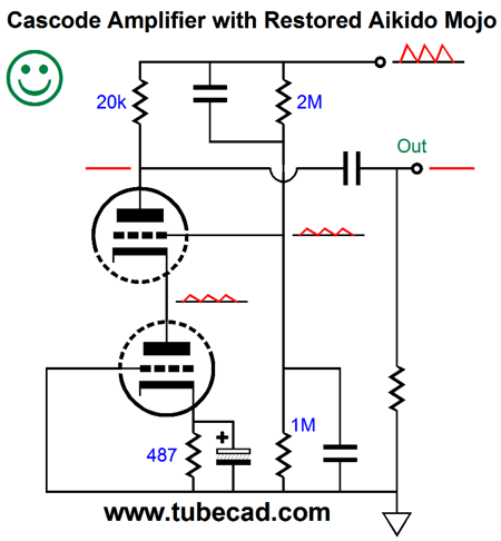
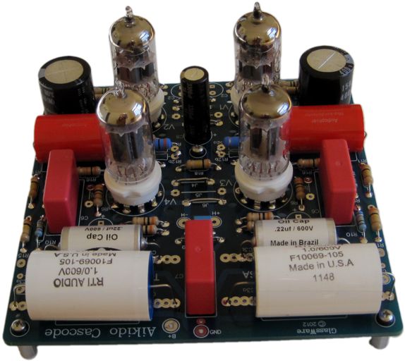
In SPICE simulations, the ratio between top to bottom capacitor was 1:4.05. The previous design example, complete with Aikido mojo but with no Rk bypass capacitor, yielded a distortion of below 0.1% with 1Vpk @ 1kHz . And its output impedance was about 19k. Yes, 19,000 ohms. Well, how do we lower the cascode's output impedance? We could use a much smaller plate resistor value, but then well will lose the high gain. One workaround is to add an Aikido cathode follower (ACF), as I did in my Aikido Cascode PCB.
A textbook cascode input circuit followed by an ACF that scrubs away the power-supply noise that the textbook cascode leaks forth.
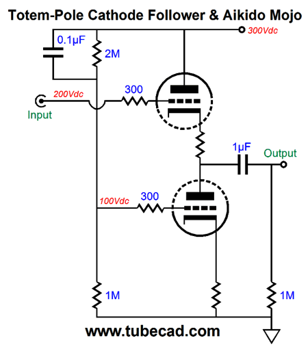
Cathode Follower and Aikido Mojo
The added cathode follower stage accomplishes two goals: it presents a low output impedance and it improves upon the cathode follower's intrinsically good PSRR; a textbook cathode follower, with constant-current loading, realizes a PSRR equal 20Log(1/[mu + 1]). The cathode follower, with Aikido mojo, greatly improves upon the already good PSRR.
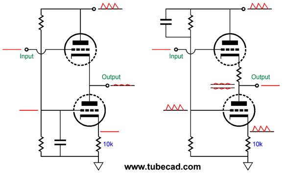
Since only a fraction of the power-supply noise leaks out of the cathode follower's cathode, we only need to realize a gain equal to that fraction, i.e. 1/(mu + 1), to null the noise. which using 240 and 10k cathode resistors allows us to achieve. Let us compare the conventional cathode follower that is loaded by a constant current source, as show on the left of the following schematic, to the Aikido mojo cathode follower on the right.
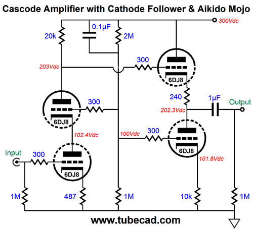
With the conventional cathode follower that is loaded by a constant current source an increase of 1V at the top triode's plate must result in 1/(mu + 1) increase in the top triode's cathode voltage. A triode's mu, i.e. its amplification factor is a measure of the grid effectiveness in controlling current flow through the triode relative to the plate. The cathode, on the other hand, is mu + 1 times more effective than the plate in producing a change in conduction. Thus, the circuit on the left must see its output rise by 1/(mu + 1) in order that the top triode maintain its fixed current flow, which is set by the constant-current source loading of the cathode follower's output. The Aikido mojo cathode follower on the right, in contrast, does not experience a fixed, steady, unvarying current flow, as the power-supply noise prompts a small varying current flow in response, as 100% of the AC portion of the power-supply noise is injected at the bottom triode's grid. Since this bottom triode functions as a cathode follower in its own right, the 10k cathode resistor will see almost 100% of the power-supply noise, say about mu/(mu + 1) worth of it. This varying current flow is in anti-phase to the power-supply noise, so as the B+ pulls upward, the bottom triode pulls down, resulting in a power-supply-noise null at the output. By the way, if the 10k resistor were replaced by one equal in value to the top triode's plate resistance, then the top cathode resistor would not be needed. So, why didn't I do just that? Far too much idle current would result. Using "too large" a bottom cathode resistor allowed me to back off on the idle current flow; adding the top cathode resistor allowed me to still achieve the noise null at the output in spite of the "too large" bottom cathode resistor value . Let's now join the mojo cascode to the mojo cathode follower.
In effect, what I have done is to cascade the very same Aikido mojo technique, as both the cascode and cathode-follower use the same PSRR enhancement approach.
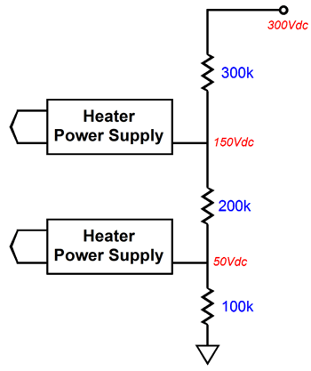
As for my fingerprints, what I like so much about this circuit, other than its simplicity and excellent performance, is that it is so me. Let a draftsman redraw the schematic and send it to Merlin Blencowe or Morgan Jones and I am sure that each would experience something of an "Ah, Dr.Lasker, I presume" moment, as both would proclaim, "Ah, no doubt, another Broskie circuit." Okay, before I strain my arm from excessive back patting, I should mention that this circuit presents one problem that many might otherwise not see: a single heater power supply cannot be used. The cascode stage holds two triodes; the bottom triode's cathode sees a few volts, while the triode's cathode sees 100V. The cathode-follower stage also holds two triodes. The top cathode sees 204V, while the bottom cathode sees 102V. Not good. A triode's maximum heater-to-cathode voltage must be observed.
The solution is to use two heater power supplies: the cascode stage would get one power supply voltage-referenced to +50Vdc, while the cathode-follower stage's would be referenced to +150Vdc.
Next Time
User Guides for GlassWare Software
For those of you who still have old computers running Windows XP (32-bit) or any other Windows 32-bit OS, I have setup the download availability of my old old standards: Tube CAD, SE Amp CAD, and Audio Gadgets. The downloads are at the GlassWare-Yahoo store and the price is only $9.95 for each program. http://glass-ware.stores.yahoo.net/adsoffromgla.html So many have asked that I had to do it. WARNING: THESE THREE PROGRAMS WILL NOT RUN UNDER VISTA 64-Bit or WINDOWS 7 & 8 or any other 64-bit OS. I do plan on remaking all of these programs into 64-bit versions, but it will be a huge ordeal, as programming requires vast chunks of noise-free time, something very rare with children running about. Ideally, I would love to come out with versions that run on iPads and Android-OS tablets.
//JRB
|
|
Kit User Guide PDFs
Only $12.95 TCJ My-Stock DB
Version 2 Improvements *User definable Download or CD ROM www.glass-ware.com |
||


| www.tubecad.com Copyright © 1999-2016 GlassWare All Rights Reserved |