| John Broskie's Guide to Tube Circuit Analysis & Design |
10 July 2017 Post Number 387
Downshift Time
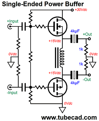
Actually, that last sentence is only half right, as he could readily understand how the two MOSFETs could pull away from each other, with the inductor in the middle being pulled apart like an accordion; but how the inductor could seemingly collapse upon itself, so the loudspeaker could experience big negative swings, made no sense to him. He is not alone in not being able to conceptualize how this magic trick is pulled off, as many tube-lovers cannot understand how a transformer-coupled, single-ended amplifier works, while apparently having no problem with understanding how a transformer-coupled push-pull amplifier works. Indeed, my guess is that they, in fact, do not understand either of the two types of transformer-coupled amplifiers, as both perform a similar magic trick.
Let's return to fundamentals. Inductors and capacitors are twins, fraternal twins with opposite features. Capacitor are voltage centric, while inductors are current centric. Where a capacitor opposes a change in voltage potential, an inductor opposes a change in current flow. A capacitor is happiest with a fixed voltage across its plates, while an inductor enjoys most a steady current flow through its leads. An ideal capacitor charged with 100V across its plates would remain charged for eternity, with zero current flow across its plates: a perfect battery, as it actually stores an electric charge, whereas batteries actually store the potential to chemically generate a voltage potential across their ends. An ideal inductor, with its leads tied together, like a snake biting its tail, would maintain a constant induced current flow eternally, a current flow without a voltage drop. If we wish to increase the voltage across a capacitor, we will need current to flow into the capacitor; if we wish to decrease the voltage across a charged capacitor, we have will to absorb current flow from the capacitor. If we wish to increase the current flow through an inductor, we will need to force a voltage differential across its leads; for example, by placing a voltage source, such as a battery across its leads. If we short a charged capacitor with a resistor, the resistor gets hot, as it experiences the resulting flow of current from the capacitor. If we place a resistor in series with a engaged inductor, the resistor also gets hot, as it experiences the resulting voltage potential created by the strained inductance releasing its stored current. If we short a charged capacitor’s plates together, a nearly-infinite current flows for an almost infinitely-small amount of time. Real capacitors are made from metal plates and wire, all of which comprise some resistance, which help protect us from exploding capacitors. Real inductors are made with iron cores and copper wire; if the inductor were perfect, then breaking its circuit would result in lightning-like sparks produced by the insanely high-voltage differential across the inductor’s leads.
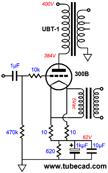
The output transformer in a single-ended amplifier resembles a constant-current source, as the primary’s inductance bucks a change in current flow. If the output tube conducts more current, the primary’s connection swings negatively. If the output tube conducts less current, however, the primary’s connection swings positively, beyond the B+ voltage, but not infinitely, as the reflected impedance from the loudspeaker’s attachment to the secondary effectively shunts the primary’s inductance, imposing a voltage-swing limit equal the idle current against the reflected impedance. In other words, the output tube’s plate might sit at 400Vdc at idle and undergo voltage swings up to 700V and down to 100V in spite of a B+ voltage of 400Vdc.
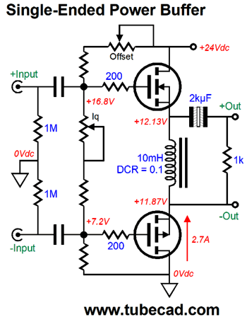
In the example of the MOSFET-based, single-ended, power buffer, the inductor allows the top output terminal to swing negatively, while the bottom output swings positively; and when the top output swings positively, the bottom output swings negatively. The loudspeaker then sees alternating polarities and reversing current flow directions. In contrast, real constant-current sources, the type we make out of electronic devices, such as MOSFETs and transistors, cannot perform this feat of magic, as they are not really constant-current sources, but current regulators that limit current, not create it out of thin air. (In SPICE, current sources create current in the absence of voltage, resulting in circuits that only work in SPICE simulations, not reality.) Because real constant-current sources cannot fold upon themselves as it were, a single-ended amplifier that uses constant-current source loading cannot exceed 25% efficiency, while the inductively loaded single-ended amplifier cannot exceed 50%. If you think that I will mention that resistively-loaded single-ended amplifiers and buffers cannot exceed 12.5%, you are wrong, as was I. Long-time reader, Paul, has pointed out to me that that 12.5% is far too high, with something closer to 8% being the actual theoretical maximum. At first, I was sure that he was wrong; as I had read the 12.5% figure so many times, I assumed it must be true. Well, after some furious scribbling and calculating, I realized that he was right. Here is my reply to him.
I was so tickled by my allusion to Auden’s poem* that I had to quote myself here, shamelessly. At the same time, after the sweet taste of self-congratulation came the bitter realization that soon any allusion to famous poems will be if not impossible, at least pointless, as no one will recognize them as allusions, as poetry nears its death. The undertaker is on call and a nice plot and tombstone have been purchased. Soon. Of course, the United States will always have the state-decreed poet laureate, just as other nations retain their pointless and emasculated royalty, more out of habit than devotion—let alone out of respect or fear. Of course, I am the first to admit that poetry could, and most certainly, will be resurrected, as it has recovered from near extinction many times before. Time always wins. One surefire, although paradoxical, way to revive poetry here in America would be to cease all government grants and subsidies; indeed, most effective of all, would be to make its creation illegal and a capital offense; and its reading and transmission a felony. If a man is willing to risk death for his poetry, then his reader will willing face jail time to read it. When the poet in the Soviet Union felt the oppressive scrutiny of some faceless official, if not his boot against his neck, he was nonetheless paid the compliment of being feared. Can you imagine any poet in America achieving the great tribute of being feared by the government? Okay returning to audio circuitry, let me embellish the MOSFET-based, single-ended, power buffer. First of all, how should we set the idle current and center the output MOSFET to ensure the largest symmetrical output voltage swings? The following design uses two potentiometers, one for each task. The top potentiometer sets the voltage centering; the bottom, the idle current. We rely on the inductor’s DC resistance to measure the current flow by reading the voltage drop across its leads.
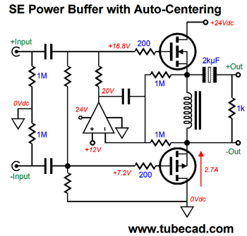
Alternatively, we could use an OpAmp to center the output stage.
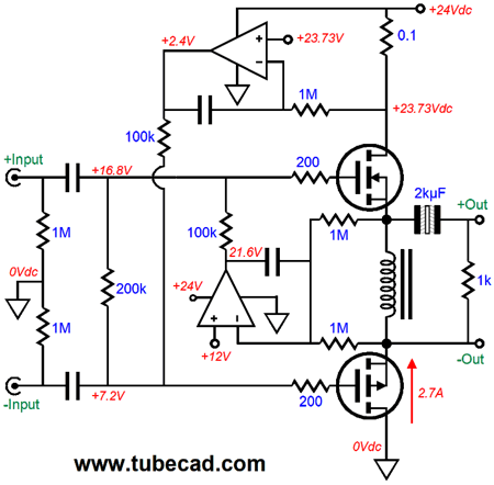
The two 1M resistors splits the voltage drop across the inductor, which the OpAmp then compares to its non-inverting input. If the voltage present at its inverting input is more positive than the voltage at its non-inverting input, the OpAmp’s output swings negative, forcing the MOSFET sources and inductor down in voltage. The OpAmp adjusts its output voltage until the middle of the inductor sits at 12Vdc. (If the inductor holds a center-tap, then only one 1M resistor is needed, as it can attach to the center-tap.) Most OpAmps are perfectly happy with a 24V differential across their power-supply pins. What most OpAmps may not be happy with is the following circuit, where the top OpAmp’s two input sit less than one 1V from the B+ voltage of 24V.
FET-based OpAmps usually work best in this application, although there are exceptions. (The OpAmp’s data sheet should reveal how close the inputs can work to the positive power-supply voltage.) This OpAmp strives to see the same voltage drop across the current-sense resistor as it sees at its non-inverting input, adjusting its output voltage to bring the two voltage inline with each other. Note that the top OpAmp tugs at the bottom of the 200k resistor between the input coupling capacitors, while the bottom OpAmp tugs at the top of the resistor. If the current-sense resistor were placed at the bottom, terminating at the ground, then the idle-setting OpAmp would have to attach to the bottom of the middle resistor, not its top; and the centering OpAmp would have to be reconfigured so that it could tug at the bottom of the middle resistor.
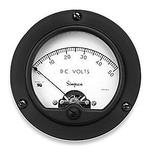
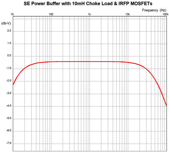
Another approach would be to retain the two potentiometers and add two analog meters. I dig old meters. I love the round shape and the spade-shaped needle point and the glass bessel. These old standards are still being made by companies such as Simpson and they do not come cheap, as they usually start at $100. The standard practice in making of electronic goods is that the actual cost of the parts and enclosure amount to 20% of the selling price. With computers, the percentage is much higher; with high-end audio, the ratio can be much lower. Well, the added $200 for meters would increase the price tag by $1,000, so they are usually left off the faceplate. Still, two 2.5” or 3” meters would impart a retro glamour to the faceplate as opposed to the clamor of blue LEDs. One meter would reveal how centered the output stage was, while the second would show the idle current. Since the class-A, single-ended output stage draws a constant average current, we do not fear rectification effects that a class-AB output stage would compel, all we need do is shunt the meter’s coil with a large-valued capacitor. If a stereo power buffer where made, a toggle or rotary switch could choose between channels for the meter readouts; and four knobs would allow independent channel adjustments. Since neither MOSFET ever completely turns off, and since they offer so low an output impedance, the inductance required is minimal. For example, in SPICE simulations, the 10mH inductor allowed bandwidth down to 10Hz.
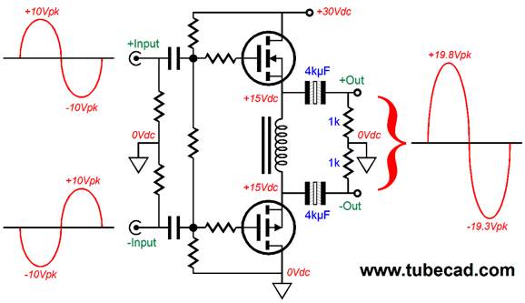
The actual two -3dB down frequencies were 7.5Hz and 85kHz. I had purposely truncated the high frequencies with 3k gate-stopper resistors, for just as I don't want the buffer to pass subsonic frequencies, I do not want it to pass ultrasonic frequencies. With the 24V switching power supply and two MOSFET, how much output power into 8-ohm loudspeaker can we reasonably expect? Normally, with a solid-state, push-pull amplifier and power supply voltage differential of only 24V, the most we could expect would be +/10V voltage swings, which into an 8-ohm load equals just 6.25W. In contrast, the use of an inductor doubles the output voltage swing to +/-20V voltage swings, which into an 8-ohm load equals a mighty 25W. (If we double the voltage again, we get 100W; double that again, 400W.)
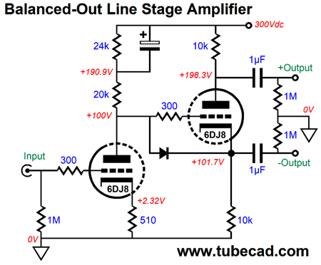
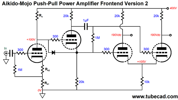
Tubes to the Rescue The following design consists of two stages, a grounded-cathode amplifier input stage and a split-load phase splitter output stage.
Note the twist: the electrolytic capacitor at the top does not terminate into ground, but the B+ connection. Am I getting senile? Perhaps I am, but the capacitor’s position is sound. The previous balanced amplifier design offers the key advantage of balanced designs: common-mode rejection ratio (CMRR). In other words, the amplifier accepts, acknowledges, recognizes, sees differential input signals, while largely ignoring those signals shared between the balanced inputs, i.e. the common-mode signals. Noise, both the common-mode power-supply noises internal to the signal source and those noises induced in the interconnects, tend to be shared equally between the balanced signals, so are subject to the differential amplifier’s high CMRR and fall out of the equation, leaving just clean signal to be amplified.
The split-load phase splitter, however, does not intrinsically offer an equal PSRR at its output. Indeed, just the damn opposite. For example, in the following design, the electrolytic capacitor and 24k resistor define an RC filter so the power-supply noise at the input triode’s plate is low, so, too, the split-load phase splitter’s inverting output.
Its non-inverting output, on the other hand, leaks almost 100% of the power-supply noise.
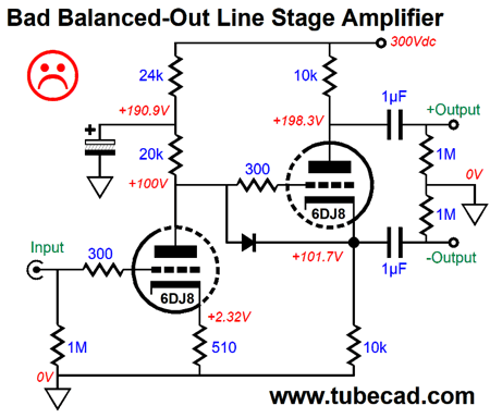
With a monopolar power supply, we will never get a great PSRR from both of the split-load phase splitter outputs, but we can—if we are dang clever—get an equally polluted PSRR from both, which means that next balanced stage can apply its high CMRR to vanquish the power-supply noise. Long ago, in post number 135, I showed how power-supply noise could be equalized after the split-load phase splitter.
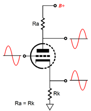
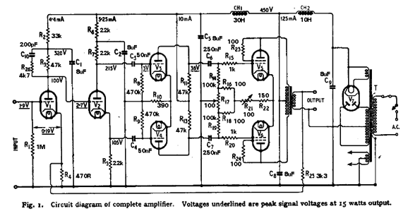
Read the post for an explanation on how this circuit works. In today’s circuit, we equalize the power-supply noise before the split-load phase splitter by ensuring that first stage’s PSRR is -6dB, a 50% rejection in other words. If half the power-supply noise emerges for the grounded-cathode amplifier, then the split-load phase splitter’s inverting output will pass along the same 50% of the power-supply noise. What about its non-inverting output? It, too, will pass along 50% of the power-supply noise and in phase with the other output. What happens is that by impressing half of the power-supply noise on the split-load phase splitter’s cathode resistor we thereby create an inverting current variation that travels through the triode up and through the plate resistor, which subtracts half of the power-supply noise present at the plate, resulting in the same amount of power-supply noise at both outputs. Let’s take one of my famous side trips. Everyone knows about the Williamson amplifier design, as it was deemed the best possible tube amplifier design by many back in the 1950s. (I understand that the great Williamson did not invent the topology, but just refined the details.)
The circuit layout consists of an input stage followed by a phase splitter followed by a differential amplifier followed by push-pull output tubes. In other words, grounded-cathode amplifier, split-load phase splitter, long-tail differential amplifier, two output tubes and output transformer. Well, if we follow certain ratios, we can vastly improve the amplifier’s PSRR.
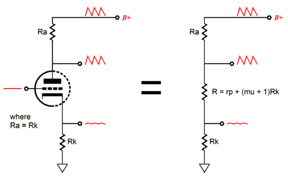
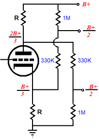
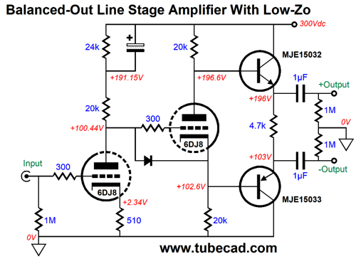
Note that the grounded-cathode amplifier input stage only gets about half of the available B+ voltage. This was done to ensure that the DC coupled split-load phase splitter sees a low enough grid voltage. (If the phase splitter’s input saw half of the B+ voltage, then the phase splitter could not work, as its triode would see a zero cathode-to-plate voltage.) If we forgo DC coupling between the stages, using a coupling capacitor instead, we could give the grounded-cathode amplifier the entire B+ voltage within to work. But we would not thereby buy ourselves any more gain from the first stage, as the stipulation that 50% of the power-supply noise must leak from its output also entails the stipulation that its gain equals half the triode’s amplification factor (its mu). The following formula sets the desired power-supply noise and gain ratios of one half. Mu/2 = (muRa) / (Ra + rp + [mu + 1]Rk) Solving for Rk, we get: Rk = (Ra –rp) / (mu + 1). Where rp is the triode’s plate resistance; mu, its amplification factor; Ra, the plate resistor; and Rk, the cathode resistor. Now, I should mention that there is a trick that allows us to get the desired ratio 0f 50% of the power-supply noise and mu/2 as gain and deliver a low enough plate to the grid of the split-load phase splitter: it’s to use an input coupling capacitor. Yes, I know that many eschew all coupling capacitors, viewing them as sonic disasters, which only $$$ will overcome. Sure, I get it. I dislike excessive coupling capacitors as much as any audiophile. The key word in that last sentence was “excessive.” When needed, a coupling capacitor can be a godsend. Stop and think about it, do you really want your transformer-coupled tube power amplifier to try to amplify 0.5Hz? I don’t. In fact, I do not want the amplifier to try to amplify any frequency below the output transformer’s natural limit. And I certainly do not want the input stage to amplify any DC offset riding on its input signal. The following design uses an input coupling capacitor and DC couples the grounded-cathode amplifier to the split-load phase splitter.
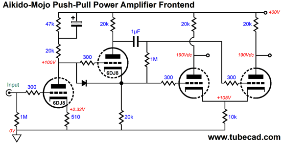
Two cathode resistors are used in series, with the top controlling the idle current flow through the triode. Both cathode resistors, however, influence the stage’s gain. Placing this circuit in the classic Williamson topology yields a superb PSRR. The long-tail differential amplifier sees 50% of the power-supply noise at each of its two inputs and at its shared cathode resistor, which results in a vastly improved PSRR, as the it creates a power-supply noise null at its two plates. Magic, Aikido-mojo magic. This trick only works if we observe a fixed ratio between the differential amplifier’s plate resistors and single cathode resistor: Rk = Ra/4 Okay, that is the end of the long detour. Returning to the tube line-stage amplifier with balanced outputs, the problem we face when driving MOSFETs is their high input capacitance. In order to charge and discharge a capacitance quickly requires current, as slew-rate times capacitance equals current: I = Slewrate x C. If we solve for slewrate, we get I/C. Slew rate can be found from formula: Slewrate = 2piFVpk / 1,000,000, where F equals the highest frequency you wish to reproduce and Vpk is the highest peak voltage swing. The 5mA that the split-load phase splitter draws may prove insufficient. One workaround is to add two beefy cathode followers after the phase splitter. Another workaround would be to add two high-voltage transistors instead, configured as emitter followers.
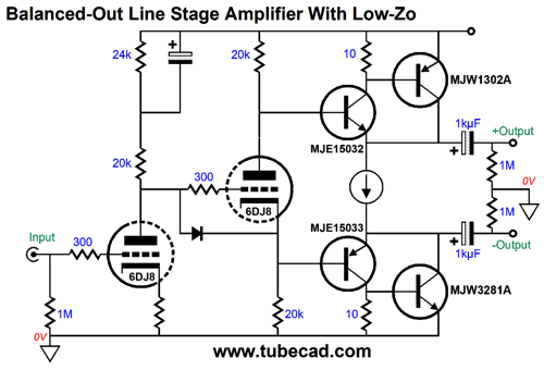
Note the similarity between these emitter followers and the single-ended, power buffer design. Yes, both operate in a single-ended fashion. This raises an interesting question, What if we replace the shared emitter resistor with a constant-current source? And what if we use this circuit to drive high-ohmage headphones instead of a power buffer? Think about it: the 300V B+ voltage and the strict class-A operation of the output stage precludes ever driving loudspeakers, unless you own some old 600-ohm speakers that were common in old HAM radio gear. But we could drive 32- to 300-ohm headphones to ear-bleeding levels with a moderately heavy idle current. Here is one possible implementation.
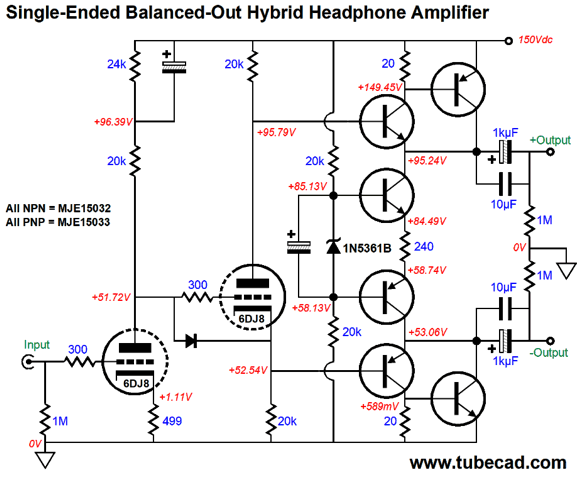
By themselves, transistor emitter followers do not offer super low distortion; but used in a compound configuration, they do. Making a two-headed constant-current source is easy enough, as it entails only four more transistors, one zener with an optional bypass capacitor, and one high-wattage 240-ohm resistor.
Note that the B+ voltage has been reduced to 150V from 300V, which allows a higher idle current through the output stage, so more power can be delivered into the headphones. Also note that the big beefy TO-247 transistors have been replaced by TO-220 devices. IN SPICE simulations, the THD came in at about 0.01% (mostly 2nd harmonic) at 1Vpk into 32 ohms at 1kHz. Not bad for a feedback-free design. The PSRR was insanely good, better than -60dB, and the Zo was below 2 ohms. I have a lot more to share on this topology, but I am already far past my self-imposed 3,000-word limit, so I will wait to the next post to continue this thread.
Next Time
//JRB
Patreon My second goal is to gather 1,000 patrons, which may seem a crazy goal, but then the world is a big place. I have 959 patrons to go. (I would be tickled to have as many patrons as I have made posts, 386.) If you enjoyed reading this post from me, then you might consider becoming one of my patrons at Patreon.com.
User Guides for GlassWare Software
For those of you who still have old computers running Windows XP (32-bit) or any other Windows 32-bit OS, I have setup the download availability of my old old standards: Tube CAD, SE Amp CAD, and Audio Gadgets. The downloads are at the GlassWare-Yahoo store and the price is only $9.95 for each program. http://glass-ware.stores.yahoo.net/adsoffromgla.html So many have asked that I had to do it. WARNING: THESE THREE PROGRAMS WILL NOT RUN UNDER VISTA 64-Bit or WINDOWS 7 & 8 or any other 64-bit OS. I do plan on remaking all of these programs into 64-bit versions, but it will be a huge ordeal, as programming requires vast chunks of noise-free time, something very rare with children running about. Ideally, I would love to come out with versions that run on iPads and Android-OS tablets. //JRB |
E-mail from GlassWare Customers
High-quality, double-sided, extra thick, 2-oz traces, plated-through holes, dual sets of resistor pads and pads for two coupling capacitors. Stereo and mono, octal and 9-pin printed circuit boards available.
http://glass-ware.stores.yahoo.net/ Support the Tube CAD Journal & get an extremely powerful push-pull tube-amplifier simulator for TCJ Push-Pull Calculator
TCJ PPC Version 2 Improvements Rebuilt simulation engine *User definable
Download or CD ROM For more information, please visit our Web site : To purchase, please visit our Yahoo Store: |
|||


| www.tubecad.com Copyright © 1999-2017 GlassWare All Rights Reserved |