| John Broskie's Guide to Tube Circuit Analysis & Design |
28 November 2016 Post 403
Special Thanks to the Special 61
If you have been reading my posts, you know that my lifetime goal is reaching post number one thousand. I have 597 more to go. My second goal is to gather 1,000 patrons. I have 939 patrons to go. If you enjoyed reading this post from me for the last 18 years, then you might consider becoming one of my patrons at Patreon.com. It would make a big difference to me. Thanks.
More on the Series Crossover I happen to like this arrangement a great deal, but I must acknowledge that most hate the idea of an external crossover. Pause and reflect, however. By placing the crossover externally, we now have ready access to it, which means that we can readily modify it; indeed, we could plug it into the wall and polarize the components inside. Or we could discard it, using two bi-amp amplifiers instead. Whether we bi-amp or just bi-wire, the makers of high-end speaker cables will be twice as happy.
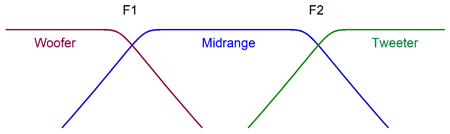
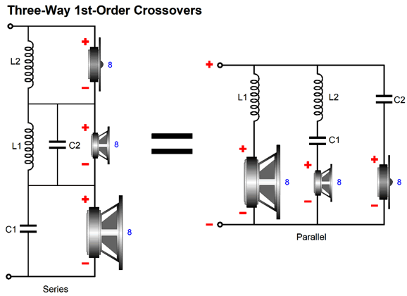
Three-Way Series Crossovers
Where C1 & C2 are in µF and L1 & L2 are in mH:
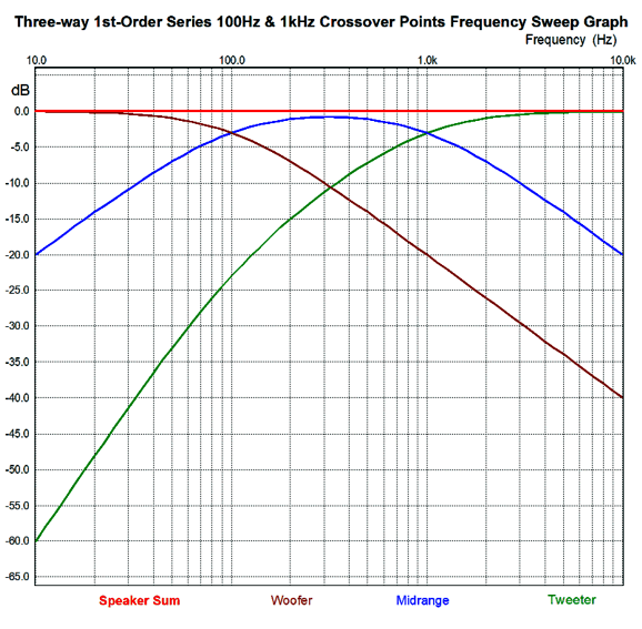
Note how the midrange is shunted by both a capacitor and an inductor. Here are the resulting frequency plots.
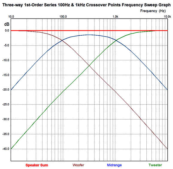
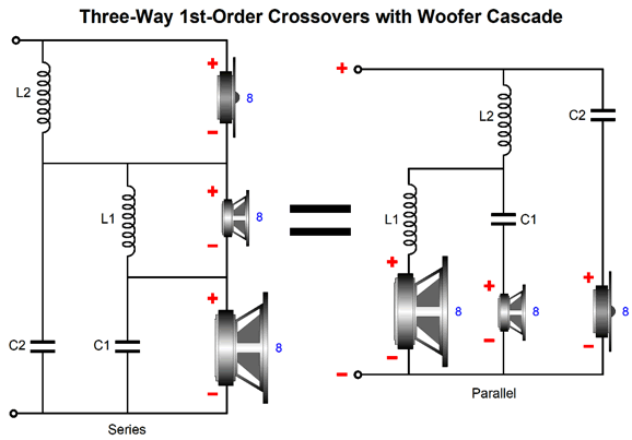
Notice how all three drivers, woofer, midrange, and tweeter, experience first-order slopes (i.e. -6dB per octave) throughout, much like the parallel three-way crossover. Also notice how the individual speaker drivers' sum is dead flat. It may look like the crossover points are shifted off their targets, but they are not. We can, however, alter the series crossover, so the crossovers cascade. Cascading retains the flat frequency response and phase integrity (with the first-order crossover), while delivering a staggeringly increasing attenuation slope for either the woofer or the tweeter. A freebie of sorts, as the same two capacitors and two inductors are used. Let's start with the cascade favoring the tweeter.
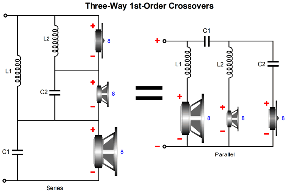
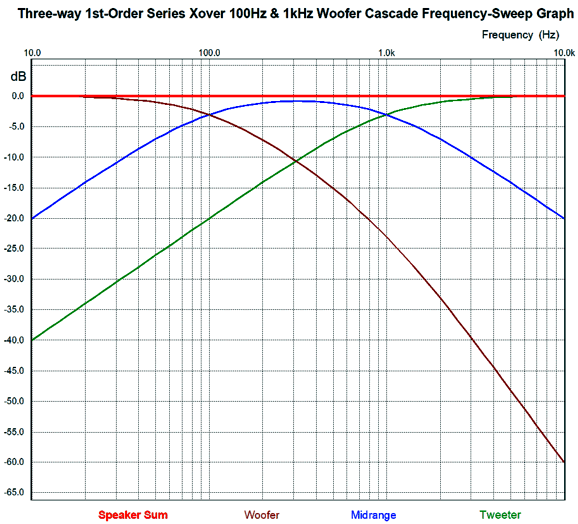
Here are the frequency plots for this version of the crossover.
Note how both the woofer and midrange crossover slopes begin and end at first-order (-6dB per octave), while the tweeter starts at a first-order slope then steepens to second-order (-12dB per octave) below 100Hz. This steepening slope will help protect the tweeter from the big low-frequency voltage swings and from amplifier hum or buzz from a broken ground connection. On the other hand, we could favor the woofer, by cascading in its direction.
The woofer now sees to crossover frequencies, 100Hz and 1kHz.
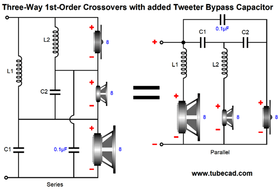
Note how the woofer is now -60dB down at 10kHz, rather than -40dB of the previous example. This increasing crossover slope will help get the woofer out of the critical midrange, where its heavy diaphragm will have the most trouble responding to quickly. Which cascade is better? My hunch is that the woofer cascade is better sounding, as the tweeter sees only one capacitor in its signal path and the woofer doesn't have to try to reproduce high frequencies. On the other hand, the tweeter cascade would prove safer, as it offers the delicate tweeter more protection. Here is a possible workaround, which could deliver better sound and safety.
The added 0.1µF bypass capacitor is small in value relative to the other capacitors, so it won't throw off the crossover frequencies. It can, however, improve the sound. The effectiveness of bypass capacitors is not linear; a 1µF bypass capacitor does not sound ten times better; indeed, it may sound worse. Quality is key here, and be sure to experiment. I have been amazed by the difference a ridiculously small-valued silver-mica capacitor can make. (I like to tack solder the bypass capacitors in place, as I usually end up trying several before finding one I like best.)
Four-Way Series Crossovers
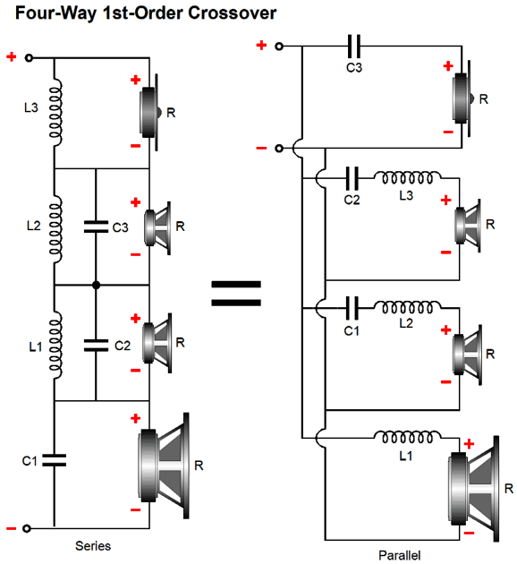
Where capacitors are in µF and the inductors are in mH:
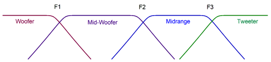
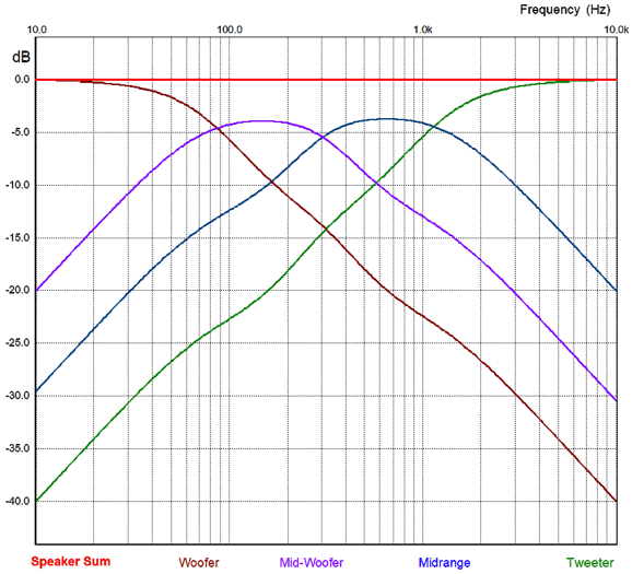
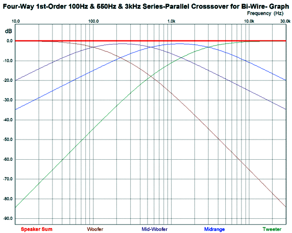
In both topologies, series and parallel, all the drivers experience the same first-order (-6dB) slopes throughout. The following graph shows 100Hz, 300Hz, and 1kHz crossover frequencies.
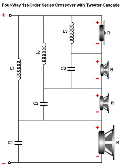
The plot-lines may look look wobbly, but they are mathematically sound. Note how the mid-woofer and midrange are down -4dB relative to the woofer and tweeter. This is the result of having all four drivers overlap so much in the middle of the frequency band. Just like the three-way crossovers, we can cascade in favor of either the tweeter or the woofer. "Favor" here means provide ever increasing attenuation slope past he crossover frequency. Here is a tweeter-favored cascade of the series crossover.
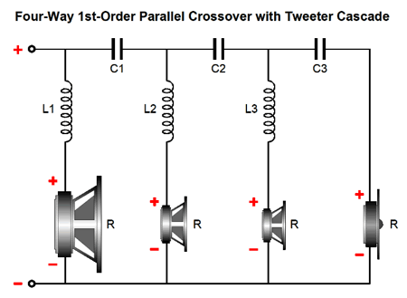
The woofer sees one inductor, while the tweeter sees three capacitors in series. We can achieve the same result in the parallel version.
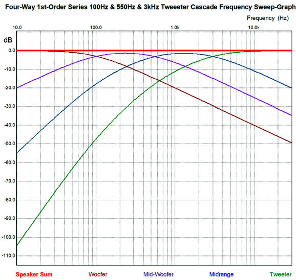
If anything, the parallel crossover better shows how the woofer only encounters one inductor to the tweeter's three capacitors. The following graph applies equally to the series and parallel cascade crossovers shown above.
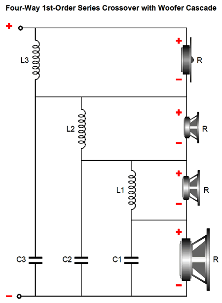
Note that the woofer, mid-woofer, and midrange all see first-order slopes the high end. The mid-woofer sees the same -6dB slope at its low-frequency cutoff. But the midrange and tweeter experience first-order slope at their low-frequency cutoffs that then steepen. If we wish to favor the woofer instead, the following cascade leans in its direction.
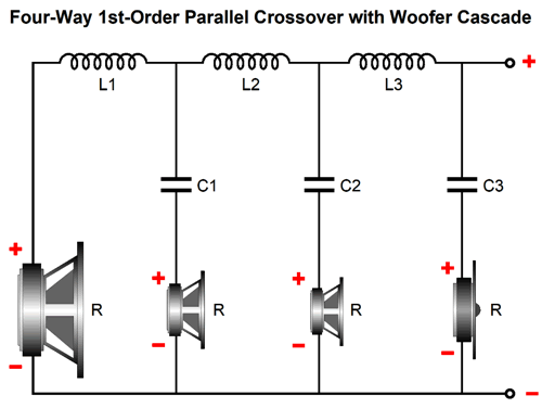
Three cascading inductors end at the woofer's positive terminal. Here is the equivalent parallel version.
Note that the input is at the right this time. I won't bother with the frequency plots, as it looks like the mirror image of the tweeter-favoring cascade.
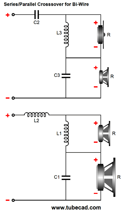
Series-Parallel Crossover for Bi-Wire
Assuming the crossover frequencies of 100Hz, 550Hz, and 3kHz from the previous example, the tweeter and midrange series crossover frequency is 3kHz, while the mid-woofer and woofer series crossover frequency is 100Hz. The parallel crossover frequency is 550Hz. Here are the frequency plots.
Note that both the woofer and tweeter initially experience first-order slopes, which then steepen to second-order. The mid-woofer and midrange, in contrast, see constant first-order slopes throughout. This might prove the best compromise, as we get the benefits of bi-wiring and safer operation of the tweeter, while the slow woofer gets out of the way of the critical midrange frequencies. Moreover, the mid-woofer and midrange will experience their own sharper, mechanical cutoffs due their own low and high-frequency limits. By the way, these three crossover frequencies, 100Hz, 550Hz, 3kHz were chosen to accord with geometric-mean ratios. What the heck does that mean? It means that if you want to divide 100 and 3,000 to their geometric middle, so each driver covers same number of octaves, you take the square-root of the product of 100Hz against 3kHz. The result is that 550/100 equals 3,000/550. Well, it does roughly, as 547.7226 is closer to correct; but being 0.5% off the mark is not bad, particularly as most crossover capacitors are truly-fine if they are 5% devices. On the other hand, 100Hz, 600Hz, and 3.6kHz works perfectly, as the square-root of 360,000 is 600. By the way, if the woofer extends down to 18Hz, then the woofer will cover an equal octave range, with the 100Hz, 550Hz, 3kHz crossover frequencies. For the tweeter to follow the ratio, its high-frequency cutoff would have to be 16.5kHz. In contrast, the 100Hz, 600Hz, 3.6kHz crossover frequencies imply a low-end cutoff frequency of 16.7Hz and a high-frequency cutoff of 21.6kHz. As far as I am concerned, the mid-woofer would be the most important driver in this loudspeaker, so that is where I would spend the most care and expense. The one big problem posed by first-order crossovers, i.e. the need for wide-bandwidth drivers, is mitigated in a four-way system. Well, wouldn't a five-way or six-way loudspeaker system be better still? It might be, but as I am sure every Saudi prince with five or six wives will tell you that the law of diminishing returns quickly catches up with you.
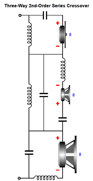
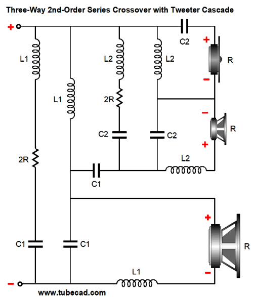
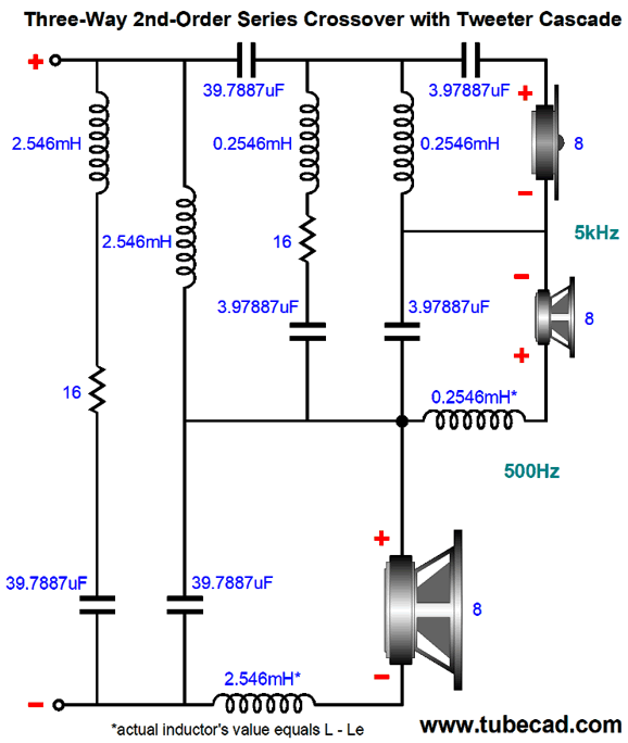
Three-Way 2nd-Order Series Crossover
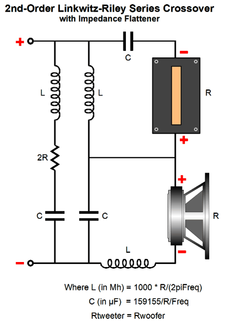
I assume that most would want the extra safety from a tweeter cascade, so here is a three-way, series, Linkwitz-Riley crossover.
Sine there are only two capacitor and two inductor values and one resistor value, I didn't bother giving each capacitor, inductor, resistor its own label. Where capacitors are in µF and the inductors are in mH:
The crossover might be complicated, but the math is easy. The result is a flat frequency response and flat impedance. Here is an example crossover with 500Hz and 5kHz crossover frequencies.
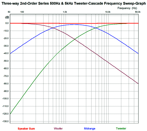
Of course, we would not use such precise values; instead, we would replace the 3.97887µF capacitor with a 4µF capacitor and the 0.2546mH inductor with a 0.25mH. Moreover, the woofer's and midrange's own internal inductance should be subtracted from the inductor in series with them. I only used these values to get a flatter result in SPICE simulations. Speaking of which, here is the frequency graph.
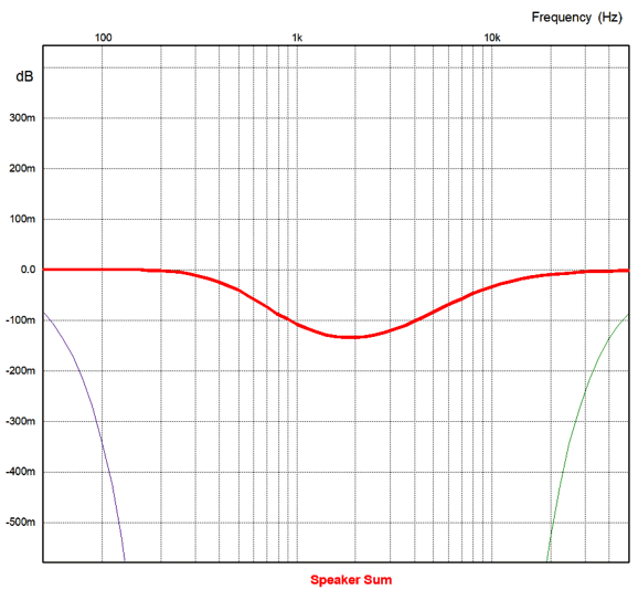
Note how the woofer and midrange both experience -12dB-per-octave rolloffs, but the starts at -12dB at 5kHz and then steepens to -24dB below 500Hz. There is a slight dip in the center, 0.13dB, which is revealed in the following closeup.
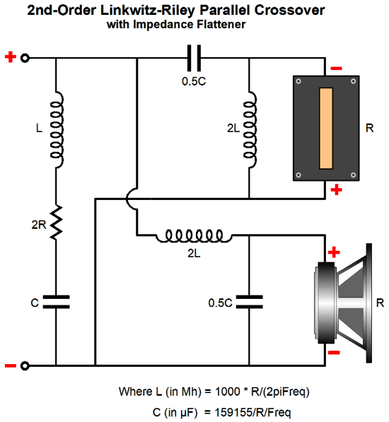
It is possible that with exact capacitor and inductor values, the dip would vanish. I won't bother showing the impedance plot, as it is flat line at 8ohms, with only 0.001 ohms deviation from 5Hz to 50kHz. What is far more important is how I got the impedance flat. Remember that in my last post I mentioned that the 2nd-order Linkwitz-Riley crossover gave rise to a doubling of the speaker impedance at the crossover frequency, which precludes its use with current-output amplifiers. I suspected that a fancy Zobel network would do the trick, but I didn't know what it would look like. Well, late one night, I was reading a review of Daniel Dennett book on consciousness, Consciousness Explained, when the impedance flattening circuit and ratios just plopped into my mind. I love the irony of reading about consciousness, while my unconsciousness mind was grinding away at math. By the way, apparently Mr. Dennett explanation is simple: consciousness doesn't really exist, in spite of what you might believe. This great news for many, as it means that there is no reason why computers, thermostats, and toasters cannot also be conscious, just in the exact same that you are not conscious. Of course its confusing, that is why it is deemed brilliant. On the other hand, if you actually did feel pain, joy, remorse, longing, lustful, then computers could not be invited to the party, as no amount of syntactic manipulation of symbols, symbols that only hold meaning because someone like you bestows meaning upon them, can never create semantics, i.e. meaning, the relationships between signs and symbols and what they represent. Alas, your hand calculator will never pine for your return, nor worry about irrational numbers, such as pi. Returning to crossovers, I quickly wrote the ratios down and went back to the review. The next morning I ran the circuit in SPICE and it looks good, as the impedance is flat.
The series version is just as easy.
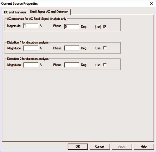
With the addition of this network, the speaker is current-out safe. And without these two networks tucked within, the previous example of the three-way Linkwitz-Riley-alignment crossover (with 500Hz and 5kHz crossover frequencies) will not work. The way I generate impedance plots in SPICE is to replace the voltage source with a current source:
I then set its AC properties to 1A and run a frequency sweep. The voltage that develops across the crossover and speakers is equal in ohms to the impedance an amplifier will see. While on the topic of SPICE simulations, I should mention that when doing frequency plot of a multi-driver crossover, be sure to add all the resulting AC voltages together before applying a dB evaluation. For example,
not
otherwise the results will be way off, as the negative dBs will subtract from the 0dB, which makes no sense as 0dB is 1,000 times greater than -60dB.
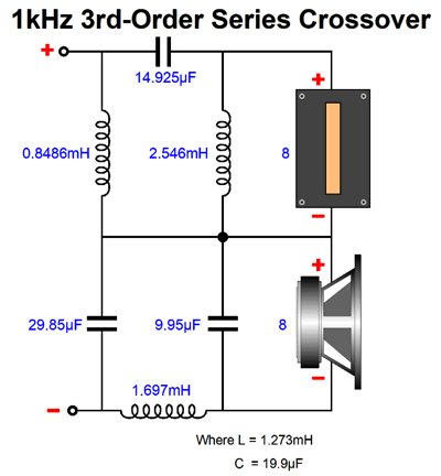
Third-Order Series Crossover
Here is a design example with a 1kHz crossover frequency.
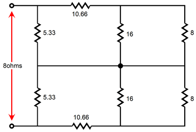
The embarrassing thing is that I had wrote his ratios down in my notebook and I instantly discounted them, as I didn't believe they would yield 1/6th of the impedance ratio to each driver at the crossover frequency, as that was what the 3rd-order parallel crossover did. At the crossover frequency with the parallel crossover, the woofer and tweeter crossovers present 16-ohms each of impedance, which in parallel results in an 8-0hm load.
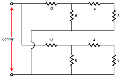
So, I knew the series 3rd-order crossover would have to present 4-ohms per half, so the two could add up to 8 ohms at the crossover frequency. I had drawn the following assemblages of impedances and dismissed it, as I thought it yielded 1/3 of the crossover signal, not the 1/6th I was looking for; all I could see was 10.66 ohms in series with 5.33 ohms or 1/3. As Homer Simpson would say D'oh!
Worse, when I transposed those impedance values into ratios in a SPICE simulation, I listed the bottom inductor as 0.75L instead of L/0.75. So, I screwed up twice. Getting old sucks.
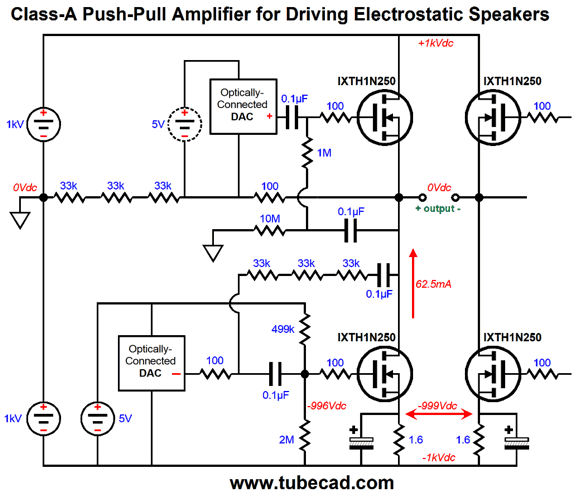
A Taste of What's Coming
By the way, I only drew the left half of the complete amplifier, but the right half just duplicates the left half. The MOSFETs do all the amplifying, which makes this a very ZEN-like design.
//JRB
User Guides for GlassWare Software Since I am still getting e-mail asking how to buy these GlassWare software programs:
For those of you who still have old computers running Windows XP (32-bit) or any other Windows 32-bit OS, I have setup the download availability of my old old standards: Tube CAD, SE Amp CAD, and Audio Gadgets. The downloads are at the GlassWare-Yahoo store and the price is only $9.95 for each program. http://glass-ware.stores.yahoo.net/adsoffromgla.html So many have asked that I had to do it. WARNING: THESE THREE PROGRAMS WILL NOT RUN UNDER VISTA 64-Bit or WINDOWS 7 & 8 or any other 64-bit OS. One day, I do plan on remaking all of these programs into 64-bit versions, but it will be a huge ordeal, as programming requires vast chunks of noise-free time, something very rare with children running about. Ideally, I would love to come out with versions that run on iPads and Android-OS tablets.
//JRB |
Kit User Guide PDFs
And
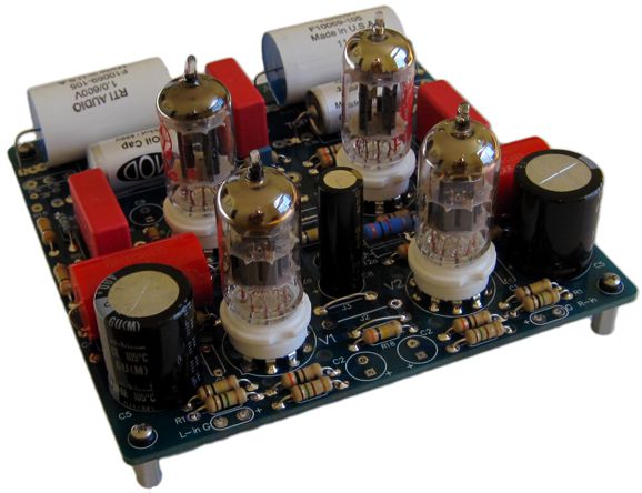
High-quality, double-sided, extra thick, 2-oz traces, plated-through holes, dual sets of resistor pads and pads for two coupling capacitors. Stereo and mono, octal and 9-pin printed circuit boards available.
Designed by John Broskie & Made in USA Aikido PCBs for as little as $24 http://glass-ware.stores.yahoo.net/
The Tube CAD Journal's first companion program, TCJ Filter Design lets you design a filter or crossover (passive, OpAmp or tube) without having to check out thick textbooks from the library and without having to breakout the scientific calculator. This program's goal is to provide a quick and easy display not only of the frequency response, but also of the resistor and capacitor values for a passive and active filters and crossovers. TCJ Filter Design is easy to use, but not lightweight, holding over 60 different filter topologies and up to four filter alignments: While the program's main concern is active filters, solid-state and tube, it also does passive filters. In fact, it can be used to calculate passive crossovers for use with speakers by entering 8 ohms as the terminating resistance. Click on the image below to see the full screen capture.
Tube crossovers are a major part of this program; both buffered and un-buffered tube based filters along with mono-polar and bipolar power supply topologies are covered. Available on a CD-ROM and a downloadable version (4 Megabytes). |
||


| www.tubecad.com Copyright © 1999-2017 GlassWare All Rights Reserved |