| John Broskie's Guide to Tube Circuit Analysis & Design |
11 February 2018 Post 412
Creating Virtual Grounds & Rail Splitting
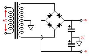
Before getting into complex circuitry, let's look at simpler solution of sorts: an AC-powered bipolar power supply. The obvious route is to use a center-tapped secondary on a power transformer.
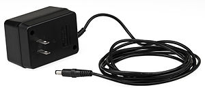
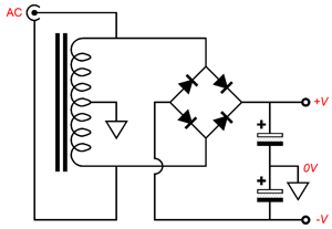
Four rectifiers and two power-supply reservoir capacitors and that's it. Or is it? The Center-tap is an essential part of this circuit, for without it we have a monopolar, not bipolar power supply. If we do want the wall-voltage entering our project's enclosure, we could use an AC wallwart. The problem here is that no center-tap is available, so we are back to a monopolar power supply. Or are we? Here is a simple workaround: a center-tapped inductor, which we can locate within the enclosure. Non-center-tapped AC enters and the center-tapped inductor creates our ground terminal. How does it work?
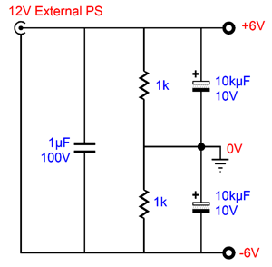
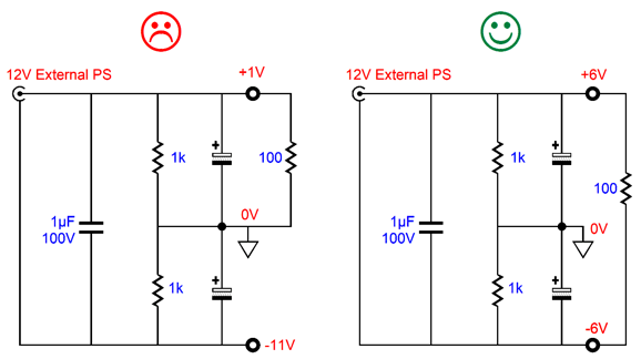
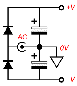
The center-tapped inductor is an AC voltage divider, splitting the input AC voltage into two out-of-phase AC voltage of half the input voltage magnitude. which allows us to create a true bipolar power supply. What does "true" mean here? True means that we can sustain heavy DC current flow from just one power-supply rail to ground. The following circuit cannot do this.
It works well with AC signals, but cannot establish a steady flow of DC current at a fixed voltage from one rail to ground. Of course, it can sustain a steady DC flow from rail to rail.
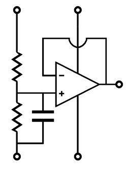
One easy workaround is to use Texas Instruments TLE2426 "Precision Virtual Ground" IC with an external DC power source.
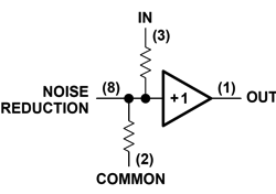
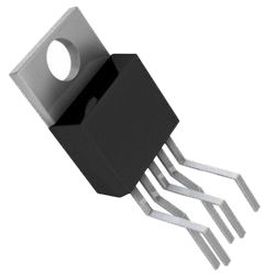
This IC holds a unity-gain stable OpAmp and a two-resistor voltage divider, the junction of which is available to us on pin 8, so a capacitor can be attached to decrease noise. Alas, this virtual-ground IC is only good for up to 20mA of current flow, which might be enough for some light signal processing, but will never drive headphones. I would dearly love to see TI come out with a 5-pin version in the TO220 package. (I used to have a spy that worked in National Semi before the company was bought by TI. We sent each other ideas and news. I need a new spy.)
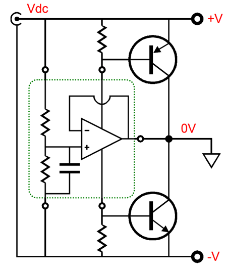
Due to the larger package and the possibility of using a good-sized heatsink, the IC could put over 100mA of sustained current flow from its virtual-ground output to either power-supply rail. Moreover, we could add two after-burner transistors externally to the IC.
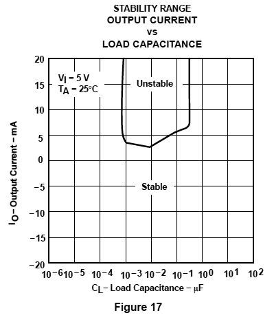
These added transistors would be normally turned off, and would only fire up when the current flow was great enough to trip their turn-on voltage. Couldn't we do the same with the stock TLE2426? We could, but we would have to drop the adjective "precision" from the title, as the current-flow through the current-sense resistors will throw off the centering of the virtual ground voltage. By the way, always carefully and completely read the data-sheet. If we do some digging into the TLE2426's data-sheet, we see the following graph, which shows the permissible values for load capacitors.
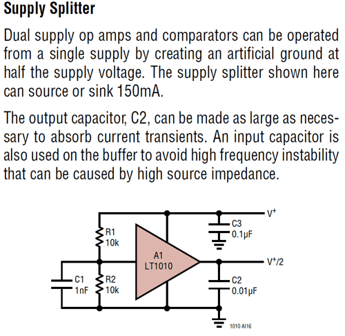
Small values work, as do big values, but those in the middle in the graph will provoke instability. Similar graphs exist for common three-pin voltage regulator, such as the LM317, and they should be consulted before grabbing some capacitor from your part bins. Linear Technology makes a power buffer in the TO-220-5 package, the LT1010, that can be used in this application. Indeed, the data-sheet recommends it:
With the addition of after-burner transistors, we could potentially get some serious current flow going.
AC Solutions
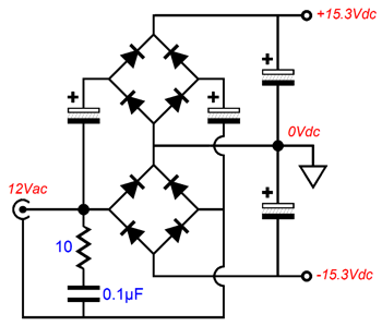
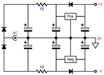
The problem with this circuit is that results in half-wave rectification, which causes the ripple to be at wall frequency, not the full-wave doubled wall-voltage frequency. In addition, the ripple is asymmetrical between the power-supply rails and is harder to filer due to its lower frequency. Still another workaround is to use eight rectifiers and four power-supply reservoir capacitors with the external AC voltage source.
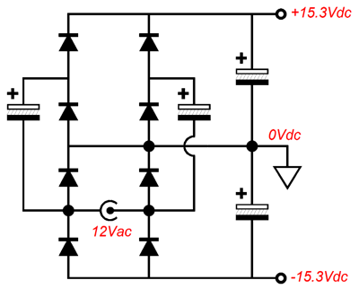
This is a full-wave double bridge rectifier circuit, with equal but out of phase ripple between power-supply rails. Okay, as I look at the above schematic, it seems more complex than it really is. Here is the same circuit redrawn, but without the RFI RC filter to make it even clearer.
The way it works is that the AC voltage ends up charging the two side-by-side capacitors, which then drive the top four rectifiers. Returning to the simple half-wave, voltage-doubling rectifier circuit, if some post regulation is applied, it can work quite well. The 10-ohm resistors form an RC filter with the capacitor on their right. This pre-filter make a huge improvement in the final DC output, as most fixed-voltage regulator ICs offer rather poor PSRR figures.
Shunt Virtual Ground Circuits
The exchange would look like this:
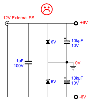
It looks good, but it assumes too much. What happens if the external DC voltage is greater than 12V? If it is a simple transformer with a bridge rectifier, then the transformer will get hot. Perhaps, hot enough to melt its plastic casing. Not good. What if a switcher-based wallwart is used that puts 12.5Vdc, not 12Vdc? Also not good, as its current limit is likely to be exceeded, resulting in it shutting down with no DC output voltage forthcoming. One workaround would be to use zener diodes with a higher break-down voltage, so they set a hard limit to how much virtual ground can move up and down in voltage.
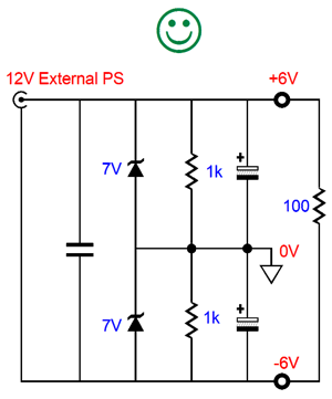
Under normal conditions, the zeners do not conduct; and only conduct when too much DC current flows from one of the power-supply rails and the virtual ground. What if we used an 18V external power supply and placed a power resistor in series with its output, couldn't we get bipolar output voltage without headaches? Indeed. But we could go even further and use a constant-current source in place of the resistor.
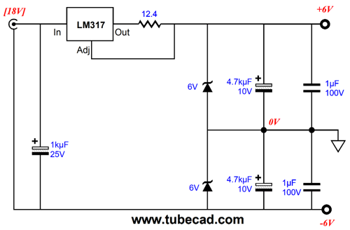
This is a shunt bipolar regulator; and like all shunt regulators, it is analogous to a class-A, single-ended amplifier. How so? Its peak current output is equal to its idle current flow. In contrast, series regulator is analogous to a class-B amplifier, which only conducts heavy current when required to do so and can idle at a fraction of its peak current output capability. In the above schematic, the current limit is 100mA, which is found by dividing 1.25V by 12.4 ohms. We can simplify the above circuit by using the three-pin regulator as voltage regulator, not as a constant-current source.
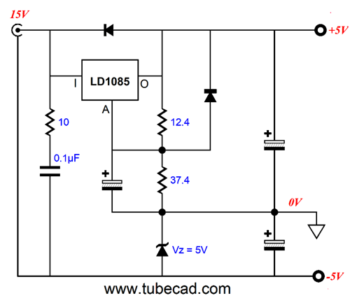
The idle current flow is the same as before—and it must be high enough to match the peak expected current flow. For example, the following circuit is limited to only 10mA of sustained DC current flow from the negative rail to the virtual ground. We cannot cheat the circuit.
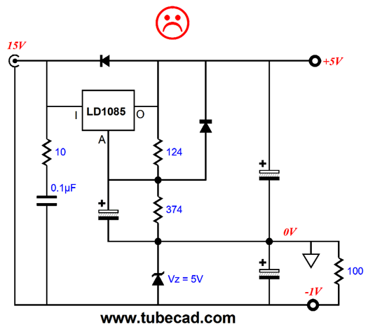
Wait a minute, John, what if we used a fixed 5V regulator instead of an adjustable regulator? It would have to work then, right? No. Alas, no. The ground pin on most fixed regulators can only see a maximum of 8mA of current flow and fixed regulators idle at 5mA, which sets the current limit from the negative rail to the virtual ground. What about the 5V zener? Yes, what about it? It can only stop voltage from exceeding its break voltage, not create voltage, as it is not a battery. Okay, what if we use both a fixed and adjustable regulator together?
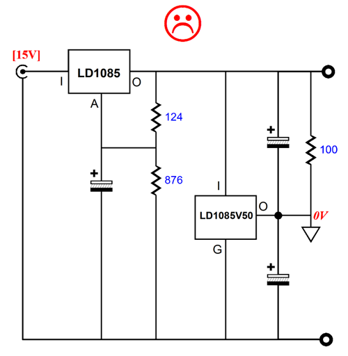
The LD1085 establishes a 10V output voltage, but the LD1085V50 (a 5V fixed regulator) probably doesn't conduct at all, so probably zero voltage develops across the 100-ohm resistor, not 5V. By the way, the quick mental test is to place a low-valued resistor across the positive output and the virtual ground and then move it across the negative output and the virtual ground. If the desired voltage across the resistor cannot be maintained, something went wrong. Of course, we do not have to use any zeners in the bipolar shunt regulator, as we can use discrete transistors and resistors to create faux zeners.
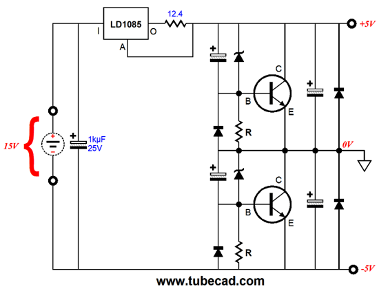
The PNP transistors strive to see a fixed voltage from their emitter to their bases equal to their turn on voltages, usually between 0.6 to 0.7 volts. The NPN transistors do the heavy lifting and deliver the heavy current flow established by the LD1085's idle current, which in this example is 100mA. Of course, we could use a complementary topology instead, as shown below.
We add zener diodes or IC voltage references to establish tighter fixed voltages, as shown below.
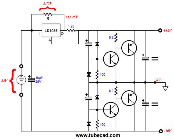
If we need truly heavy current flow, the following could prove useful.
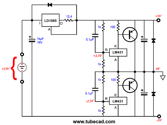
This rail-splitter circuit draws 1A of current at idle. The PNP transistors will conduct 900mA of the 1A, while the NPN transistors draw the remaining 100mA. The LD1085 gets a helping had with the addition of resistor R, as this parallel resistor share the current-flow burden, but does not compromise the constant-current source's high output impedance. If R's value is 5.5 ohms (two 11-ohm resistors in parallel), it will share half of the 1A of current flow, i.e. 500mA. Or we could use two LM431 (TL431) shunt voltage reference ICs to establish the rail voltages.
The LM431 wants to see exactly 2.5V at its reference input pin relative to its anode pin. In this setup, the LM431 will draw about 6mA, while the PNP transistor will draw 94mA.
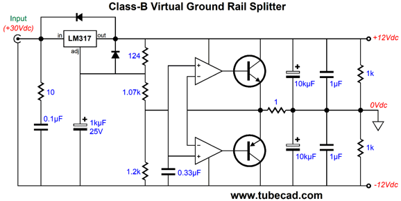
Class-B Rail-Splitting Virtual Ground
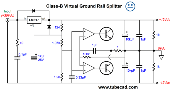
The LM317 accepts the raw 30V from the external power supply and regulates it down to 24V. The two OpAmps then see half of the 24V as their common input signal. At idle, both transistors hover near cutoff, as the micro-second one begins to conduct too much, the output voltage will stray from its target and the controlling OpAMp will switch it off, which is why this topology is sometimes referred to as a switching amplifier. If any unbalanced current flows into or out of the virtual ground, the OpAmps will ensure that the output does not stray too far from its target. A dual OpAmp that is unity-gain stable can be used. And a smaller-valued resistor could replace the 1-ohm output resistor. This series resistor should never be removed altogether, however, as it is needed to shield the amplifier stage from the big capacitors. Could the negative feedback loop terminate on the other side of the series resistor? Perhaps. I would want to run many SPICE simulation first. Perhaps, a better way to go would be the following design.
The feedback AC couples to the amplifier's output, while the DC feedback extends to the virtual ground output. Once again, I would perform many more SPICE simulations before actually building this design, but it does look promising.
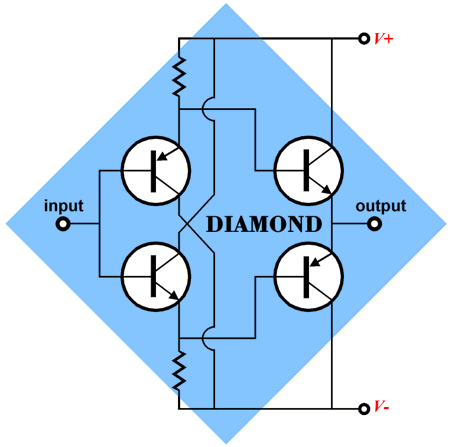
Diamond-Based Rail Splitters
The added speed-up capacitor makes a big improvement in performance. Indeed, we further improve the diamond's performance as unity-gain buffer with the following circuit.
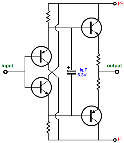
This variation allows much bigger AC voltage swings, almost rail-to-rail, but which will not be needed in a rail-splitting circuit. Making a rail-splitting virtual ground out of a diamond circuit is easy enough:
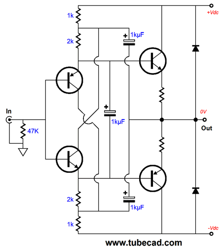
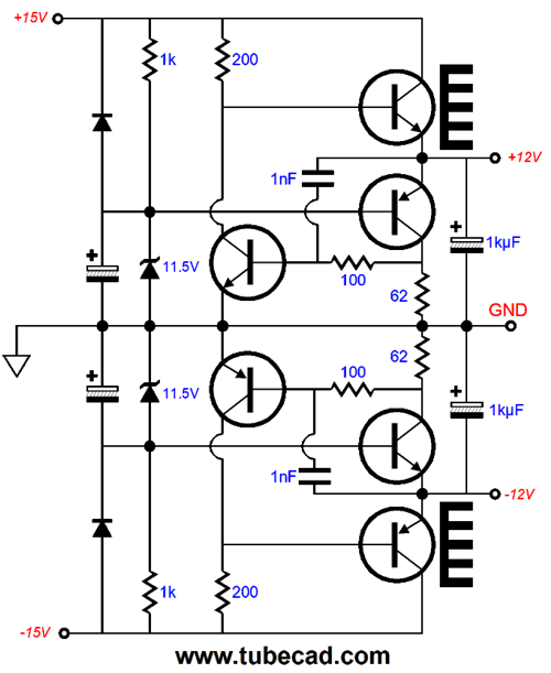
The only problem with this arrangement is that the virtual ground voltage will shift up and down with the varying sustained current flow through the 1-ohm emitter resistors. This may not prove a deal breaker, depending on the application. What might prove a deal breaker, however, is that the raw DC voltage from the external power source is left raw, with no filtering or regulation being applied. The following design overcomes both of these potential problems.
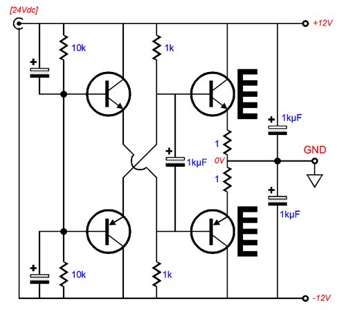
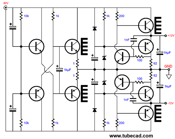
While the diamond's output might move up and down, relative to the two voltage regulator it does not matter, as their output move up and down the change in diamond output voltage. Another possible circuit to add to the diamond is the Triadtron, configured as a voltage regulator.
(The above circuit assumes a preexisting ground can be used.) Adding it to the diamond is easy enough.
Once again, it little matters if the diamond's output shifts, as the Triadtron will track its movement, so the amplifier being powered will never see the voltage shift.
Class-AB Virtual Ground
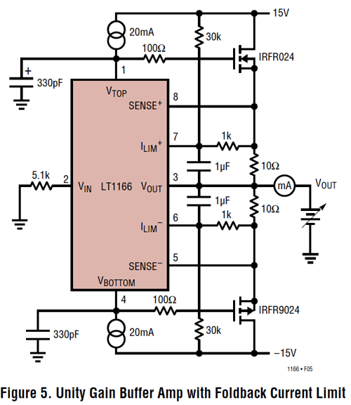
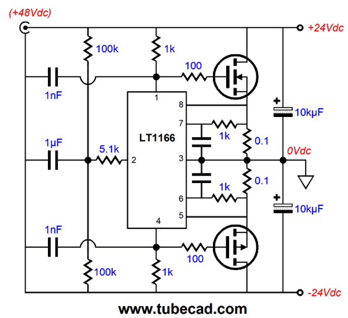
And now, here is what I have had in mind since I first discovered the LT1166 in Robert Cordell's wonderful book, Designing Audio Power Amplifiers:
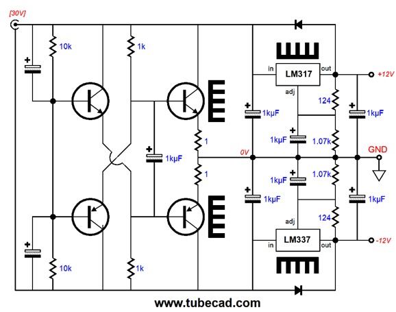
The 0.1-ohm source resistors set an idle current flow of 200mA through the power MOSFETs. This class-AB rail splitter could be used with chip power amplifiers, such as the LM3886, and would allow the amplifier to deliver 25W into 8-ohm speakers. The 48V power source could be a beefy, yet small desktop switcher. The following rail-splitter circuit uses LM317 and LM337 voltage regulators to do the rail splitting.
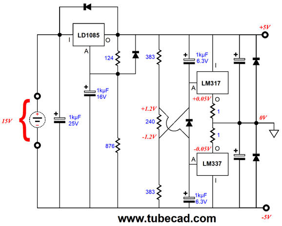
At idle, this circuit will draw 60mA from the external power supply, quite bit more than class-B, but far less than a class-A shunt regulator would draw. The DC output impedance is 0.5 ohms and and the peak output current can exceed 1A. My good buddy Arn Roatcap of GoldPoint has used a variation on this circuit for years now. Because I am ending with this circuit, do not believe that is my favorite. If I had to build a rail-splitter circuit today, I would start with this one:
Why? I love the idea of solidity nested within a floating voltage source.
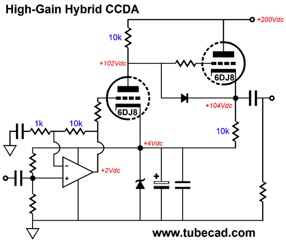
High-Gain Hybrid CCDA Amplifier
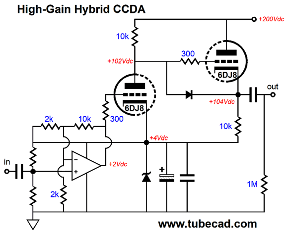
This circuit provides a huge amount of gain (about 250 or +48dB), which might be needed as a microphone amplifier. We might be able to lose on capacitor, as shown below.
I could on making changes, such as eliminating the input coupling capacitor, but this is a good place to stop.
//JRB
User Guides for GlassWare Software Since I am still getting e-mail asking how to buy these GlassWare software programs:
For those of you who still have old computers running Windows XP (32-bit) or any other Windows 32-bit OS, I have setup the download availability of my old old standards: Tube CAD, SE Amp CAD, and Audio Gadgets. The downloads are at the GlassWare-Yahoo store and the price is only $9.95 for each program. http://glass-ware.stores.yahoo.net/adsoffromgla.html So many have asked that I had to do it. WARNING: THESE THREE PROGRAMS WILL NOT RUN UNDER VISTA 64-Bit or WINDOWS 7 & 8 or any other 64-bit OS. One day, I do plan on remaking all of these programs into 64-bit versions, but it will be a huge ordeal, as programming requires vast chunks of noise-free time, something very rare with children running about. Ideally, I would love to come out with versions that run on iPads and Android-OS tablets.
//JRB |
John Says Thanks the Special 61 Only those who have produced a technical white paper or written an article on electronics know just how much time and effort is required to produce one of my posts, as novel circuits must be created, SPICE simulations must be run, schematics must be drawn, and thousands of words must be written.
If you have been reading my posts, you know that my lifetime goal is reaching post number one thousand. I have 588 more to go. My second goal is to gather 1,000 patrons. I have 939 patrons to go.
And
High-quality, double-sided, extra thick, 2-oz traces, plated-through holes, dual sets of resistor pads and pads for two coupling capacitors. Stereo and mono, octal and 9-pin printed circuit boards available.
Designed by John Broskie & Made in USA Aikido PCBs for as little as $24 http://glass-ware.stores.yahoo.net/
The Tube CAD Journal's first companion program, TCJ Filter Design lets you design a filter or crossover (passive, OpAmp or tube) without having to check out thick textbooks from the library and without having to breakout the scientific calculator. This program's goal is to provide a quick and easy display not only of the frequency response, but also of the resistor and capacitor values for a passive and active filters and crossovers. TCJ Filter Design is easy to use, but not lightweight, holding over 60 different filter topologies and up to four filter alignments: While the program's main concern is active filters, solid-state and tube, it also does passive filters. In fact, it can be used to calculate passive crossovers for use with speakers by entering 8 ohms as the terminating resistance. Click on the image below to see the full screen capture.
Tube crossovers are a major part of this program; both buffered and un-buffered tube based filters along with mono-polar and bipolar power supply topologies are covered. Available on a CD-ROM and a downloadable version (4 Megabytes). |
||


| www.tubecad.com Copyright © 1999-2018 GlassWare All Rights Reserved |