| John Broskie's Guide to Tube Circuit Analysis & Design |
31 July 2018 Post Number 433 New Products
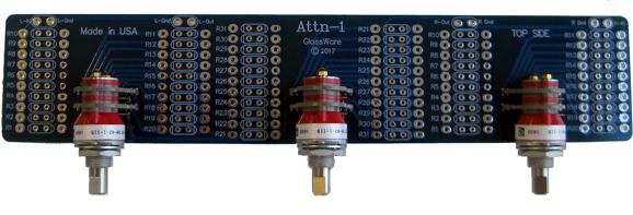
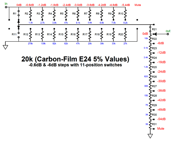
New Product: Atten-2 With the stepped attenuator, on the other hand, high-quality fixed resistors replace the thin resistive track and, likewise, high quality switch contacts replace the metal scraper. Because tight-tolerance resistors are readily available, there is no problem in following the logarithmic taper accurately and consistently. The new Atttn-1 is similar to the A3 attenuator in that it, too, hold three rotary switches with 3-inch spacing, but differs in that the sealed switches in the Attn-1 hold gold contacts and offer 11 positions, not 6. The new Attn-1 stepped attenuator uses both series and ladder attenuators, with three rotary switches to yield a total of 99 possible decrements of attenuation in 0.6dB steps, which means we can step down to -59.4dB in -0.6dB decrements.
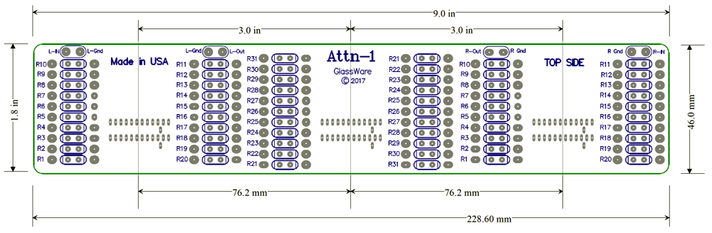
The leftmost and rightmost switches hold eleven positions and are mono ladder attenuators for the left and right channels, with only two resistors switched in at a time, attenuating up to -5.4dB per channel, with a mute in the final position. The center switch cascades from the two flanking switches and it defines a stereo series attenuator with 11 resistors in series per channel, with -6dB decrements, establishing a maximum of -54dB of attenuation, with a hard mute in the final position.
The two flanking switches also double as balance control. In other words, I park the left and right flanking switches at the -3dB middle position and then use the center switch to set the volume.
In spite of the coarse -6dB steps, I usually get close to the desired volume level. But if some adjustment up or down is needed, I use the flanking switches. More often, however, I use the flanking switches to restore balance. Many recordings need this adjustment. And with some systems, one channel plays louder than the other, which is more common in negative-feedback-free tube designs, due to tube mismatch. In other situations, one loudspeaker may sit near thick curtains, while the other sits near a reflective wall, so it seemingly plays louder. For me, 1dB steps are enough of a decrement for adjusting the balance, but with the Attn-1's flanking switches offering -0.6dB steps, an even finer balance can be achieved. It's been over a decade since I sold the fancy, Elma-based stereo stepped attenuator.
It wasn't cheap, as the switches cost a fortune; but then, the switches were worth the expense, as they held hard-gold contacts. Although gold is not as conductive as silver, it does offer one big real advantage in an audio-signal switch: gold does not tarnish, whereas silver does. When switching wall voltage in an out, the silver's tarnish is not a big deal, as the high current and high voltage can puncture the black silver oxidation. But with delicate audio signals, the tarnish builds and builds until the contact no longer makes contact. There are two workarounds. The first workaround is have big open switch structure that allows you to apply contact cleaner to the tarnish, restoring the conductivity; the second is to use a rotating knife-switch scrapper that cuts away the tarnish and thin slice of silver with each rotation. The problem with this second workaround is that, over time, silver shavings collect at the bottom of the switch and can short out contacts and cause problems elsewhere within the electronics enclosure. In contrast, hard gold stays clean.
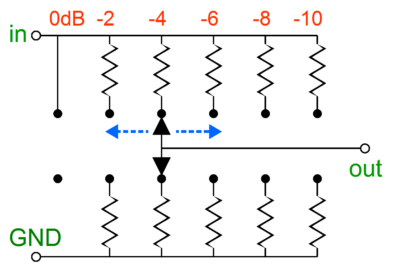
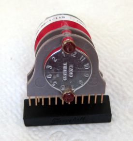
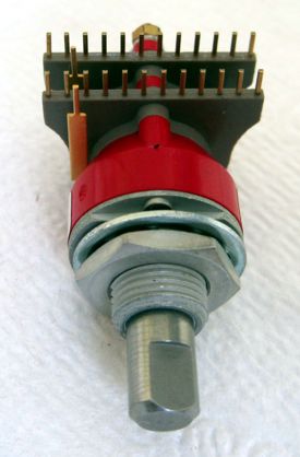
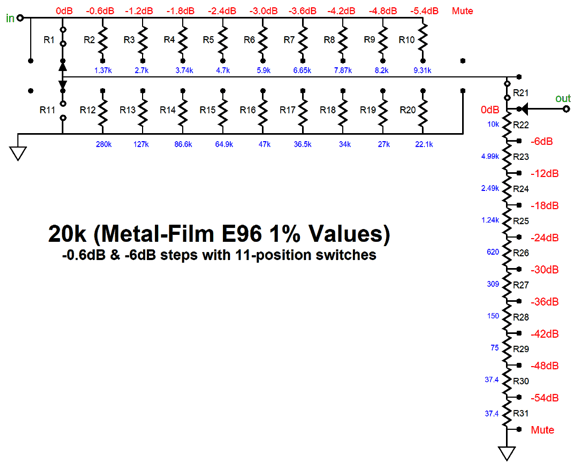
Well, I finally found an alternative to the Elma switches that uses gold contacts and is PCB mountable. Grayhill is a big name in switches and is American made. The switch holds two decks (two poles) and twelve positions. The only problem is that no one stocks the switch, not even Grayhill. Instead, you pay for at least 25 of them and then wait, as that batch will have to be made by Grayhill, which can take months. A huge pain, in other words. I discovered that the eleven-position version of the switch (and which can be used instead) was occasionally stocked by some of the big electronics distributors, so I bought as many of these that I could, but that didn't amount to that many. So far, I have enough to complete five Attn-1 kits. With the 11-position switches, 29 resistors are needed per channel. Here is the schematic for one channel and the resistor values for 1% metal-film resistors.
Or, we can use 1W carbon-film resistors, which is what I used in my build.
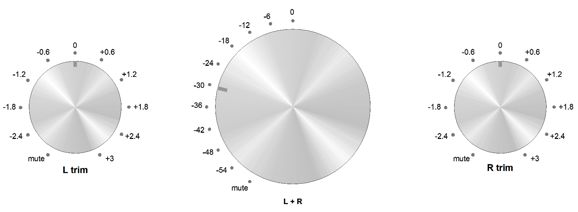
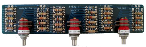
In my own build, I used 1W carbon-film resistors, placing half on the bottom and half on the top of the PCB, which gives the fat 1W resistors more room.
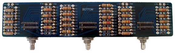
Here is the bottom view.
The new Attn-1 kits, with or without resistors are available at the GlassWare-Yahoo store.
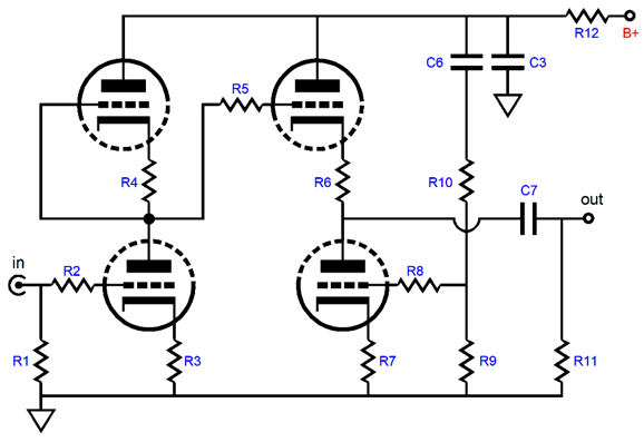
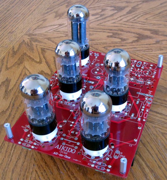
New Octal Aikido All-in-One The Aikido topology makes an excellent line amplifier, as it offers low distortion, low output impedance, and excellent power-supply noise rejection—all without a global feedback loop. The Aikido amplifier portion is almost identical to the Rev. E Aikido octal PCB, save for all the heaters sharing the single regulated power supply and its use of only one output coupling capacitor per channel.
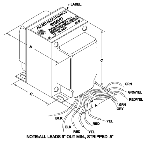
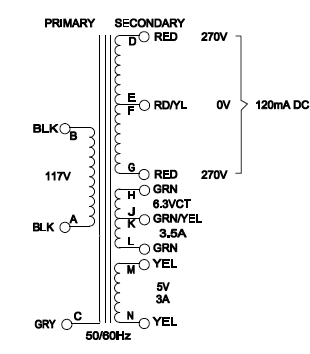
The list of possible tubes is not overly long: 2C50, 6BL7, 6BX7, 6H30Pi, 6SL7, 6SN7, 6SU7, 12SL7, 12SN7, 12SX7, 5691, 5692, 6080, ECC32. The only stipulations are that the two triodes within the envelope be similar and that the tube conforms to the 8BD base pin-out. Additionally, both input tubes must match each other as should both output tubes. In other words, don’t use a 5691 as the input tube in one channel while using a 6SL7 in the other (their heaters draw differing currents). This All-in-One design requires a conventional tube power transformer, which must hold a 5Vac winding for the tube rectifier and a center-tapped high-voltage secondary, along with a beefy 6.3Vac heater winding. The transformer I have used half a dozen times is made by Hammond and sold exclusively by Allied Electronics, the 6K56VG. Allied finally caught on that they were under-pricing the transformer, so the price is now about $10 higher now than what I was paying for it just a year or two ago. Nonetheless, it is still a bargain at $60.12.
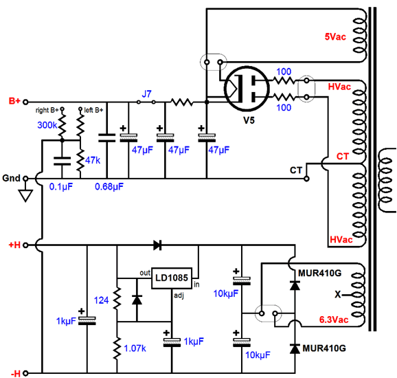
The 6.3Vac winding that feeds heater power supply must offer at least 3.6 times more current than the heaters will draw. Since four 6SN7s will draw 1.2A @12.6v, which seems to be too high for a 3.5A heater winding; but as the a 5Y3 only draws 2A, not 3A, and since the 6SN7s will not draw 120mA, this transformer works just fine. Here is the new Aikido octal PCB's power-supply schematic .
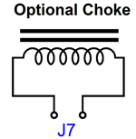
Note the three 47µF 500V capacitors, which might seem small in value compared to values used in solid-state rectified power supplies. Large values are a bad idea, however, when it comes to tube rectifiers. Why? The tube rectifier cathode cannot handle the high current spikes that a large capacitors force through rectifier's cathode. Most tube rectifier specifications state a maximum capacitor value of 50µF or 60µF, so the 47µF plays it a bit safe. Moreover, the two 100-ohm resistors at the rectifier's anodes also limit the peak surge current through the rectifier. The two capacitors after the RC resistor add an additional 94µF to the total capacitance. For those who can never get enough iron, jumper J7 can be replaced by an optional external choke.
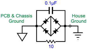
Another useful feature is the inclusion of a house-ground circuit on the new All-in-One PCB.
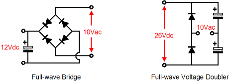
The heater power supply makes use of a 6.3Vac heater winding, which normally cannot be used to power a regulated heater power supply, as 6.3Vac rectifies up to about 7.5Vdc, which does not allow enough voltage headroom for a solid-state regulator, even an LDO type. The All-in-One's heater circuit overcomes this problem by using a voltage-doubler-rectifier circuit, which develops about 16Vdc from 6.3Vac. Here is a comparison between the full-wave bridge and full-wave voltage doubler rectifier circuits.
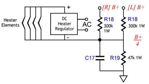
The formula for finding out how much DC current a 6.3Vac heater winding can yield in this circuit is: Imax = Iac/3.6 where Iac is the heater winding's AC current rating. For example, if the 6.3Vac winding is rated to put out 3.6A of AC current, we can get 1A of regulated 12.6V DC voltage. Resistors R18 & R19 define a two-resistor voltage divider that allows referencing the heater power supply to some positive voltage. This is an important feature when the circuit holds one triode atop another, as in the Aikido and SRPP circuits. I like to split the difference; for example, if the bottom triode's cathode sits a few volts above ground potential and the top triode's cathode rests a few volts above 100V, I would reference the heater power supply to about 50Vdc.
So much for the power-supply portion of the schematic for the new Aikido octal PCB.
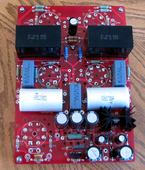
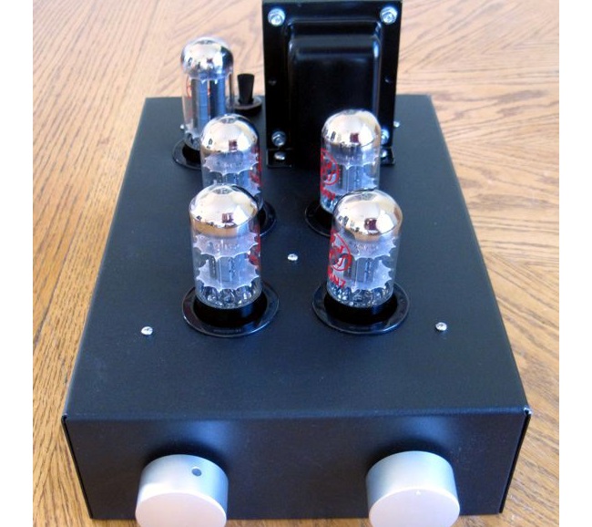
The above photo show my own build of the new All-in-One design, which placed all the parts, other than the tube sockets, on the bottom of the PCB, as I wanted the tubes to protrude from the chassis.
What you see above is the bottom of the PCB. Note the two 50µF/550V polypropylene RC capacitors.
The PCB is extra thick, 0.094 inches (inserting and pulling tubes from their sockets won’t bend or break this board), double-sided, with plated-through heavy 2oz copper traces. In addition, the PCB is lovingly and expensively made in the USA.
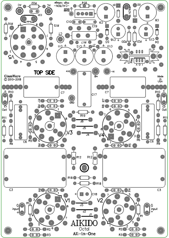
The boards are 8.5 by 6 inches, with five mounting holes, which helps to prevent excessive PCB bending while inserting and pulling tubes from their sockets. Each PCB holds two Aikido line-stage amplifiers; thus, one board is all that is needed for stereo unbalanced use (or one board for one channel of balanced amplification). For more detail on my own build of this new All-in-One, see post 431. The new Aikido octal All-in-One PCB and kit are available now at the GlassWare-Yahoo store.
Kick-Butt Audio
I have to admit to having had an intense ambivalence to this goal, in the true meaning of the word "ambivalence," not the more modern washed out meaning that downgrades the word to just mean indifference, but something closer to the dictionary's definition of "simultaneous and contradictory attitudes or feelings (such as attraction and repulsion, love and hate, pro and con) toward an object, person, or action." [from the German Ambivalenz : Latin ambi-, ambi- + Latin valentia, vigor (from valēns, valent-, present participle of valēre, to be strong] I have always longed for a sonic virtual reality, but feared that its pursuit was philistine.* I particularly feared that this might be true, decades ago, after a rich audiophile had showed me his mega-buck system. I was impressed, but wondered where his music collection was stored. I had been looking at it, it being no more more than about twelve LPs, most of which were audiophile test records. At other extreme, I once knew an avid music lover who owned over 250,000 records, but whose stereo didn't cost much more than $250. Surely, the right balance lies somewhere between these two extremes. But I now have a much greater appreciation for marginal differences, tiny, wee, minuscule differences that can make the decisive difference between enjoying or not enjoying a recording, which much like the difference between getting a joke and not getting is not marginal, but infinite. Here is an other analogy, imagine you are connecting the dots and have no idea what picture is hidden, until that one magic dot, which cannot be more than 1/100th of all the dots, yet its connection allows you to see the horse or sailboat. In other words, a small incremental improvement may effectively yield huge increases in listening enjoyment. For example, a friend once told me that his having placed a few squares of toilet paper between his loudspeaker and their stands made all the difference to him; and I believed him entirely, although I am sure that no laboratory test would reveal any measurable difference. When I first tested the new AIkido octal All-in-One build shown above, I first listened to the Aikido octal stereo Rev. E Aikido octal setup that was powered by a PS-21 fully regulated power supply. I then paused and switched in the All-in-One, and pulled the 6SN7 tubes from Rev. E and plugged them in the All-in-One. My goal was to limit the time between listening session to less than a minute. The two definitely sounded different and I preferred the sound from the Rev. E build. Upon returning from my vacation, I let the All-in-One burn for 12 hours, just in case was something to burning in, although I believe that we listeners burn in, not the equipment. I sat down for some serious listening I quickly realized that I was not even close to comparing apples to apples, as the two subwoofer amplifiers were not engaged in the new setup, which in itself makes a huge sonic difference. Second, the resistors used differed, as the Rev. E held MELF metal-film types, while the All-in-One held Japanese carbon-film types. And, finally and most importantly to me, the All-in-One build holds a GoldPoint stepped attenuator with no provision for balance adjustment. The recording I had listened to requires a small shift to the left to sound correct, which I was able to do with the Rev. E build, but not with the All-in-One. After switching to a different album and including the subwoofers, the result was that Aikido line stage amplifiers sounded more alike than different, with the differences being easily debatable as to which is better. In other words, no slam dunk either way. Except for the lack of a balance control. I need one. I won't be happy without one. For me, it makes or breaks a stereo system. On the other hand, I know that many audiophiles cannot adjust the balance, as their systems make no provision for it; and even those who could, but refuse to do so. Why not? Half of the answer is found in laziness and the other half in some strange obedience to the notion of the recording engineer as auteur, whose definitive preferences and sonic choices are never to be questioned let alone to be altered. Weird, dang weird is this belief, so much so that I have a hard time wrapping my head around it. I have encountered it many times with audiophiles, who extend the honor to speaker designer, the amplifier designer, the cable designer, basically to anyone other than themselves. One friend owned what I was sure was a broken DAC, as the sound from it was painfully bright. He refused to entertain such blasphemy, as the DAC had got a rave review. There is some logic for you. The next time I visited him, I brought two 1-inch circles of 1/4in felt. I placed them on the speaker grill cloth, over where the tweeters were located. Much better, far better sound. He complained that the felt circles were ugly. I pointed out that he could simply remove his grill frame from the speaker stick the circle on the other side of the cloth, which required no glue, as the bristly fibers adhered to the cloth on their own. He was horrified at the thought of compromising the speaker designer's efforts, so he needlessly suffered the screechy highs. I have mentioned here before another friend whose speakers held, I was convinced, out-of-phase midranges, but he was unwilling to make the test, as he could never go against the speaker designer's dictates. Here is the full story from post 321:
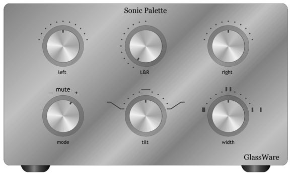
At the other extreme, I once knew an accomplished audiophile, for whom nothing was fixed and free from his control and domination. For example, he asked me if I noticed anything different with his system. I did, but I could not say what it was. He had moved the door in the wall that stood between his speakers. It bothered him that the door was not centered with the speakers, so he moved it over a foot. He disliked seeing cables, so he built a second wall, with a crawl space between it and the original wall, so the cables could be hidden from sight. (I know this fellow who suffers zero compunction when it comes to going directly to the chef in the kitchen and telling what changes he needs to make to a dish.) Well, with the introduction of the Attn-1 and the discovery of the 11-position Grayhill switches, I can imagine building something that I have longed for many years: a sonic palette control.
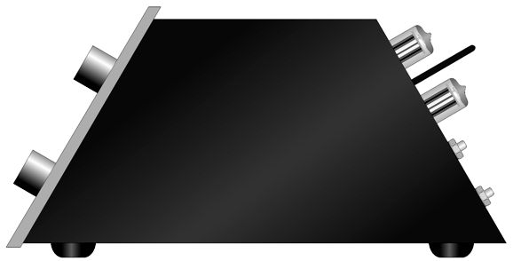
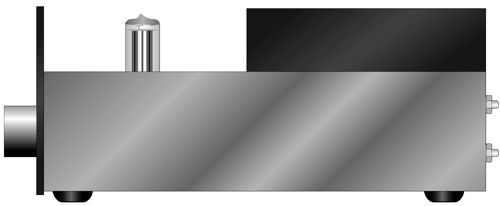
It would fit between a DAC and the power amplifiers. Not only volume and balance can be adjusted, but the signal phase and sonic stage width, along with a sonic tilt control. Here is a side view of the device.
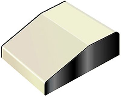
What looks like an antenna is just a metal handle, which protects the tubes located at the rear of the enclosure. Another chassis choice might be a keyboard enclosure, much like the one shown below.
They are made in various sizes, with some up to 20 inches wide. The tubes could protrude from the flat portion at the end, while the knobs would sit on the sloping portion, whit two wood sides added for snazz appeal.
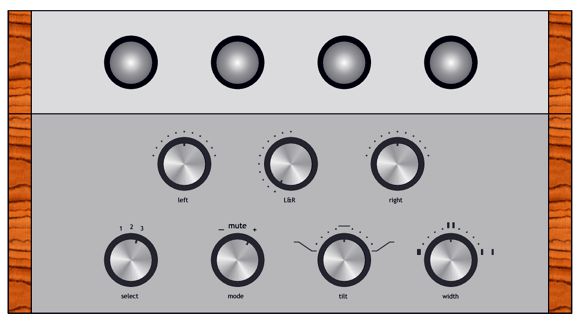
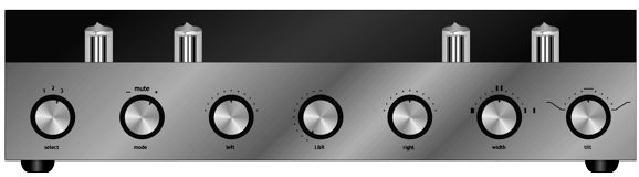
Since an input switch is included, this would serve as a full-function line stage amplifier. Of course, something far more conventional could be built.
We could get a bit fancier by using a smoked plate glass front panel.
This would allow us to see the tubes, but make it harder for our kids and pets to touch them. But far more important than its looks would be its functionality. I would love to have this much sonic control over the music I listen to. How would we actually implement the features? The best solution would be to start with an input transformer with a 1:1 winding ratio. Jensen Transformers makes some fine ones that require a 20k load termination, which the Attn-1 would provide. Due to its use of ladder and series attenuators, the Attn-1 presents a constant input impedance. Either balanced or unbalanced input signal source can be used with the input transformer. A GlassWare Select-Phase switch would then select between inverted or muted or non-inverted output signal. The sonic stage width control would require one Grayhill 11-posistion, two deck switch and a bunch of resistors. The tilt control with 11 positions will require Grayhill 11-posistion, four- deck switch and a bunch of resistors and capacitors. Such a switch may not be attainable, but the existing three-position GlassWare Tilt-2 Control could be used in the mean time. The actual signal amplification could be handled by two Aikido mono PCBs or one of the Aikido stereo PCBs, depending on the look desired. Consider this the start of a series of post on the topic of kick-butt possibilities.
Extra Super Simple Tube Circuits
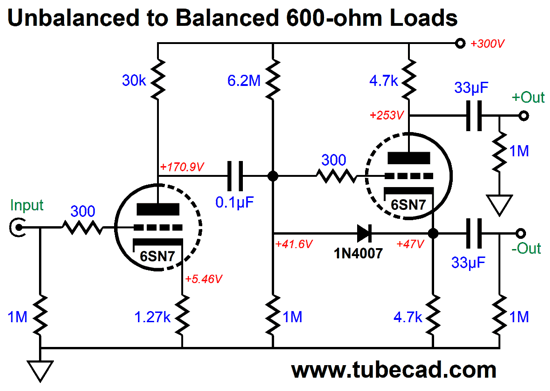
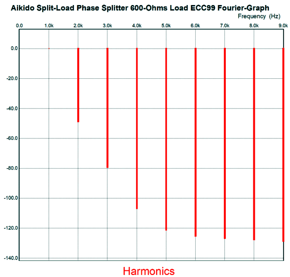
The assumption is that a 600-ohm load will be driven and that load is either an input transformer or a differential amplifier that exhibits a good amount of common-mode-rejection ratio (CMRR), as this circuit offers a PSRR of only -6dB relative to ground, but a stellar PSRR relative to the two outputs to each other. In other words, both outputs hold the same amount of power-supply noise and in phase, so an input transformer or a differential amplifier will simply ignore the noise, the noise being a common-mode signal. In SPICE simulations, the THD came in at about 1% with 1Vpk at 1kHz into 600-ohm loads.
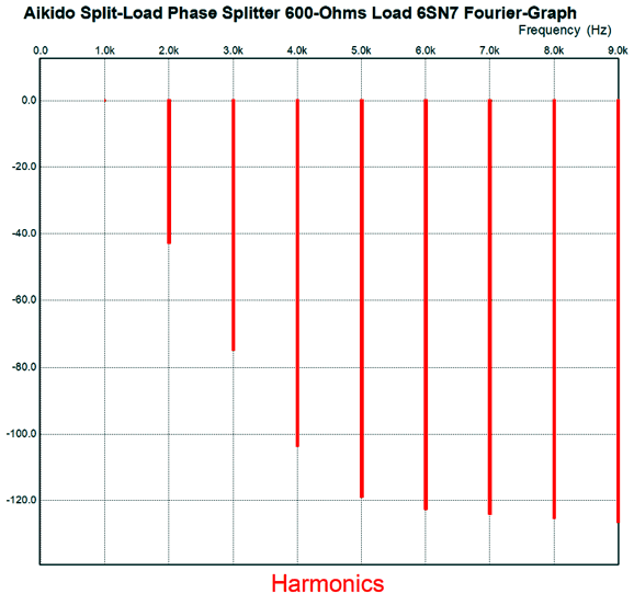
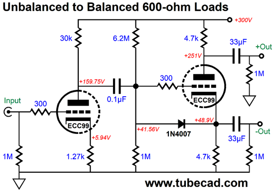
The gain was 8 or +18dB. I thought the distortion a tad high, so then tried an ECC99 in place of the 6SN7.
The resulting DC voltages are bit different, but the big difference is in performance.
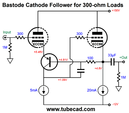
The THD fell to 0.36% and the gain rose to 13.8 or +22.8dB. Here is a Bastode-based cathode follower for 300-ohm loads, such as headphones, which also uses an ECC99 tube.
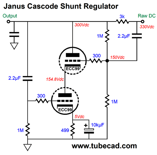
The unmarked PNP transistor was a 2N2905A and the unmarked capacitor was 30pF in SPICE simulations. The THD was so low that I won't bother showing the Fourier graph. A negative power-supply rail is needed, but this -12V rail could also power the ECC99's heater element. The intended load is a 300-ohm headphone, but of course it be used with higher impedances. Still using an ECC99, here is a variation on the Janus shunt regulator.
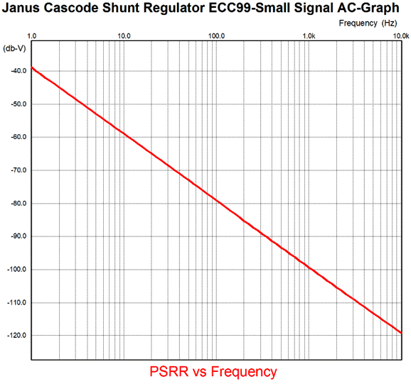
Sorry, but this schematic reads from right to left, which troubles many readers, save those living in Israel. Raw DC voltage enters at the right, and clean DC voltage exists at the left. The top triode eliminates the ripple at the raw DC side from appearing on the left side of the 3k resistor, while the bottom triode works to clean up the AC signal at the output, which could easily be induced by the circuit being powered. The unmarked capacitor is 10µF in value. Each triode sees roughly the same cathode-to-plate voltage because of the two 1M resistor voltage divider that appears on the left of the 3k resistor. By the way, the 3k cannot be replaced with a 300-ohm or a 30k resistor, as 3k is the value that results in a ripple null on the left side of the 3k resistor. If a different tube were used, a different series resistor value would be needed. Here is the SPICE-generated graph that shows PSRR versus frequency.
The frequencies are those coming from the raw DC right side of the schematic. The key frequency to look at is 120Hz, as that is going to be the ripple frequency here in Northern America.
Music Recommendation: Johnny Hartman
NPR interviewed A.B Spellman about this album and he said:
Tidal offers it in an MQA version along with 14 other albums. What you waiting for? Get listening. You can thank me later.
//JRB
*Philistine "How do you know that the fault lies not with the chicken and her eggs, but with you; perhaps your nose is out of order." "Okay, then explain why coffee, chocolate, Tabasco sauce, rye bread… still taste the exactly same as they did when I was young." He had a point and I was stupid to argue with him, as he took his cooking and meat very seriously and he would readily drive 100 miles to buy his steaks at the best butcher he could find. Moreover, the recent reintroduction of free-range chickens and their eggs prove his point, as they have more flavor than alternative that were fed only cracked corn. Well, in days past, dictionaries had more flavor. Dr. Johnson's dictionary held witticisms and outright jokes, something the Oxford English Dictionary sought to eradicate, although some unintentional humor snuck in, as the New York Times pointed out:
My first American Heritage Dictionary defined a "philistine" as one who is annoyingly indifferent to artistic or spiritual values." This quote comes from my memory, as my old dictionary was long ago replaced by its more boring, flavorless version. Merriam Webster defines it today as, "a materialistic person who is disdainful of intellectual or artistic values." In contrast, my 1927 New Century Dictionary defines it as, "one looked down upon as lacking in and indifferent to enlightenment, culture, esthetic refinement, etc. , or contentedly commonplace in ideas and tastes." Far more flavor. Also note how Merriam Webster would never go so far as to disdain the philistine's disdain of values, in contrast to those older dictionaries that did. Stop and think about it: isn't part of why we love tube sound is that is offers more flavor?
If you enjoyed reading this post from me, then you might consider becoming one of my patrons at Patreon.com
User Guides for GlassWare Software
For those of you who still have old computers running Windows XP (32-bit) or any other Windows 32-bit OS, I have setup the download availability of my old old standards: Tube CAD, SE Amp CAD, and Audio Gadgets. The downloads are at the GlassWare-Yahoo store and the price is only $9.95 for each program. http://glass-ware.stores.yahoo.net/adsoffromgla.html So many have asked that I had to do it. WARNING: THESE THREE PROGRAMS WILL NOT RUN UNDER VISTA 64-Bit or WINDOWS 7 & 8 or any other 64-bit OS. I do plan on remaking all of these programs into 64-bit versions, but it will be a huge ordeal, as programming requires vast chunks of noise-free time, something very rare with children running about. Ideally, I would love to come out with versions that run on iPads and Android-OS tablets. //JRB |
John Gives
Special Thanks to the Special 66
I am truly stunned and appreciative of their support. In addition I want to thank
All of your support makes a big difference. I would love to arrive at the point where creating my posts was my top priority of the day, not something that I have to steal time from other obligations to do. The more support I get, the higher up these posts move up in deserving attention. Only those who have produced a technical white paper or written an article on electronics know just how much time and effort is required to produce one of my posts, as novel circuits must be created, SPICE simulations must be run, schematics must be drawn, and thousands of words must be written.
If you have been reading my posts, you know that my lifetime goal is reaching post number one thousand. I have 567 more to go. My second goal is to gather 1,000 patrons. I have 934 patrons to go. Help me get there.
Support the Tube CAD Journal & get an extremely powerful push-pull tube-amplifier simulator for TCJ Push-Pull Calculator
TCJ PPC Version 2 Improvements Rebuilt simulation engine *User definable
Download or CD ROM For more information, please visit our Web site : To purchase, please visit our Yahoo Store: |
|||


| www.tubecad.com Copyright © 1999-2018 GlassWare All Rights Reserved |