| John Broskie's Guide to Tube Circuit Analysis & Design |
|
2 September 2018 Post 437
The English have an expression, V & V, which stands for valves and vinyl. And what a nice combination they make. Well, now you can have a tubes and LPs at a discount.
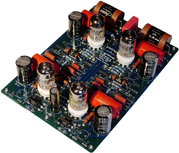
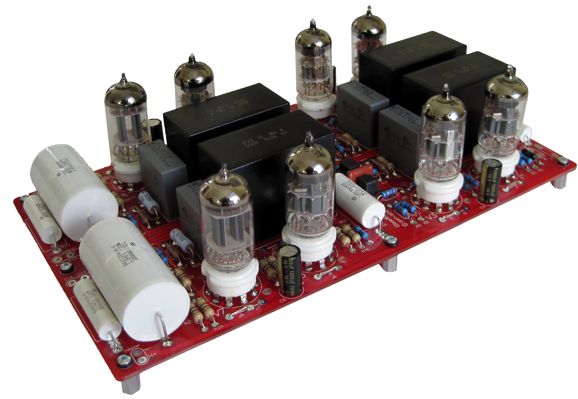
Tetra and PH-2 PCBs On Sale
Visit the GlassWare-Yahoo Store now.
Hope
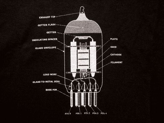
She went on to explain to me what the RMAF was. I would have been no less surprised if she had asked me if I knew about Heraclitus' definition of justice and how it differed from Plato's. This young Sherlock Holmes had seen the diagram of a 12AX7 printed on the front of my shirt and deduced that I must be a tube-loving audiophile. (How many 20 year-old males know what a 12AX7 looks like?) When I finally found my voice, I asked her if she was dragged to the event or did she go on her own. Her answer was that she dragged her father along. We talked a bit about the show and we lamented the insane expense of so much of what was shown there, but she added, "We can dream can't we?" The fact that she was a she and not a he thrilled me and I left the store entertaining the idea that perhaps there was hope; perhaps, audio can regain some of its lost vigor.
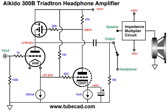
Dual-Use Triadtron Amplifier
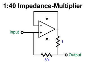
We can set the impedance ratio with two resistors; for example, 3.9 and 0.1 ohms or 39 and 1 ohms.
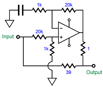
The only problem is few IC power amplifiers are unity-gain stable. The workaround is to throw away some negative feedback with the following circuit.
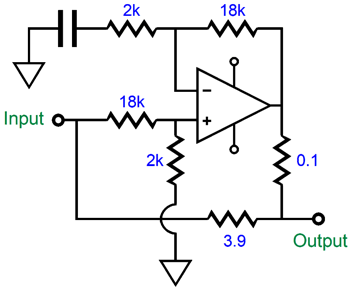
The two-resistor input voltage divider reduces the gain by 1/21 and the two negative feedback resistors set the amplifier gain to 21. In other words, unity gain,as 1/21 against 21 equals 1. The amplifier is still amplifying, but its input signal is attenuated. On the other hand, if the power amplifier's minimum gain is 10, we could use an input attenuator of 0.1 and set the amplifier's gain to 10.
Actually, the IMC's input impedance is equal to the multiplier's impedance ratio against the loudspeaker impedance plus the 3.9-ohm resistor's resistance. The 3.9-ohm resistance will define a two-resistor voltage divider with the 320 load impedance. Thus, a tad bit more than 32Vpk would be needed coming from the Triadtron to realize 32Vpk at the 8-ohm loudspeaker. This is not a problem, as 100mA against 323.9 ohms equals 32.39Vpk, which the 300B-based Triadtron can provide. I like the idea of dual-use. I have read of a restaurant that displayed three different personas. In the morning, it served breakfast items; at noon, a different group of staff made lunch foods; and at night, it became a different restaurant altogether and served fine dining, with an entirely different set of staff and decor. Well, I like the idea of a 300B-based headphone amplifier that can transform into a power amplifier. It could directly drive headphones from 16- to 300-ohms in impedance; and indirectly, 8-ohm speakers. Another approach is to forgo the headphone amplifier feature and build a 300B-based Triadtron power amplifier robust enough to drive loudspeakers from the start.
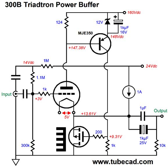
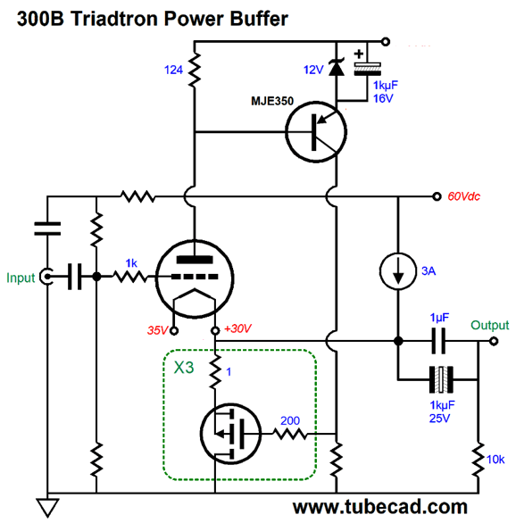
Triadtron Power Buffer
The P-channel MOSFET must now idle at the combined current flow of the constant-current source and the 300B, i.e. 1.1A. But as the MOSFET's source-to-drain voltage at idle is only 13.6V, its dissipation is only 15W, which will require a good-sized heatsink, but not a huge one. In contrast, the constant-current source will dissipate about 10W, which requires a heatsink with a thermal resistance of only 2.6°C/W. The result is an amplifier that can achieve 8Vpk output voltage swings into 8-ohm loads, which equals 4W of power, about half of what a 300B would deliver in a single-ended amplifier with an output transformer. If we want the full 8W, then the peak output swing will have to be increase by the square-root of 2 (1.414) and the constant-current source will have to idle at 1.4A. In addition, the 300B's cathode voltage will have to be raised by a few more volts. We can achieve this goal either by increasing the grid's DC voltage or by increase the 300B's B+ voltage. Because this single-ended amplifier uses a constant-current source, the efficiency falls to half (a theoretical maximum of 25%) what an inductive load would yield (a theoretical maximum of 50%). This inefficiency prevents us from going too wild and building a 100W version. Still, a 4W amplifier might be perfect for a bedroom system or a computer-speaker. Indeed, with horn loudspeakers, it would roar. To quote the young woman, "We can dream can't we?" To get 16W with 8-ohm loudspeakers, we need 2Apk current swings; to get 36W, 3Apk; and 64W, 4Apk. And in terms of voltage: 16W, 16Vpk; 36W, 24Vpk; and 64W, 32Vpk. To achieve these wattage goals the 300B's cathode voltage must exceed the required peak voltage by at least 6V and the constant-current source's power supply voltage must be high enough to encompass the peak positive voltage swing and the cathode voltage combined. For example, if we were shooting for 36W, the 300B's cathode voltage would have to be at least 30Vdc and the 3A constant-current source's power supply voltage would have to be at least 54Vdc; in fact, it would have to be higher still, as the constant-current source will exhibit a dropout voltage of its own, which might be as high as 3V. Thus, the constant-current source's power-supply voltage should be closer to 60Vdc. Now, we face the problem of excessive dissipation from the MOSFET, as it will dissipate 90W at idle. The workaround would be to place a few MOSFET in parallel, with each getting its own 1-ohm source resistor to prevent current hogging.
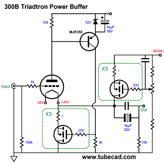
With three MOSFETs, each MOSFET dissipates 30W, which is still plenty hot. The constant-current source will also dissipate 90W, so it should be made up of three P-channel MOSFETs.
Note the potentiometer. Its addition to the circuit allows us to tweak the constant-current source idle current. In addition, we could add a toggle switch so that two idle current values could be selected, say 1A and 3A. Why? With 1A of current flow, the amplifier would put out 4W into 8 ohms, which would be suitable for quiet background listening. With 3A of current flow, the amplifier would put out 36W into 8 ohms, which would be optimal for serious listening and impressing of friends. One limitation of this 300B-based amplifier is that the gain is so low, slightly below unity-gain. The low gain was a feature in a headphone amplifier, but with a power amplifier it becomes a liability of sorts. For example, a passive line stage would be out. On the other hand, few tube-based line-stage amplifier cannot deliver the needed clean output voltage swing to achieve full power from the Triadtron amplifier. (If a different triode were used, say 5687 or ECC99, then the higher resulting gain would unload the line-stage amplifier.)
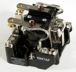
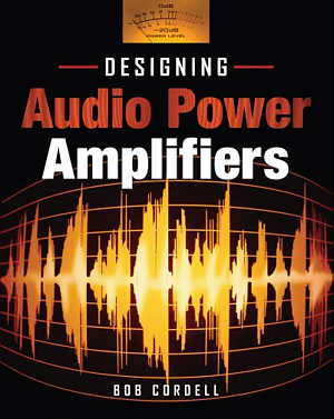
Relays When I have restored oldish solid-state power amplifiers, the first thing I do is replace as many electrolytic capacitors as I can and replace the relay, if it holds one. (Fuses also get replaced.) Invariably, the result is a much cleaner sound. Bob Cordell delivered an insightful examination of relay-induced distortion in his book, Designing Audio Power Amplifiers. (A must own book, by the way.)
Super-Triode Input Stage for a Phono Preamp
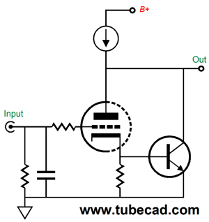
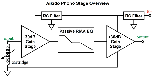
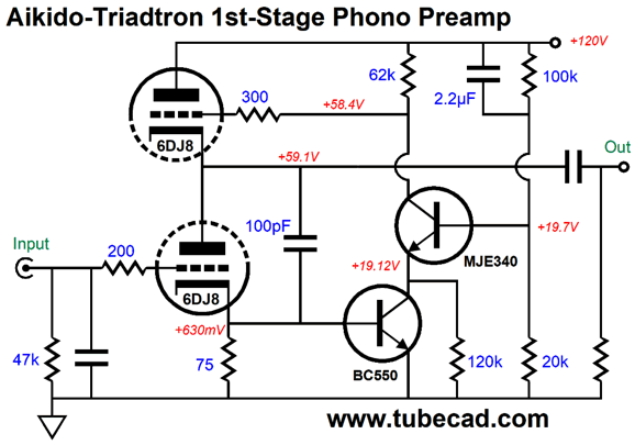
The transistor monitors the triode's cathode voltage. If the triode's current conduction varies, the transistor works to counter this variation by pulling the plate voltage down or letting the constant-current source pull the plate up. The result is that the triode works under a constant-current conduction, which means that its plate must invert and amplifier the grid signal by the triode's amplification factor (mu). A 6DJ8 presents of a mu between 30 and 33, which would yield a gain close to +30dB. Two such stages in cascade would yield +60dB. Place a passive RIAA equalization network in between the stages and the gain is reduced by -20dB, resulting +40dB for the phono preamp.
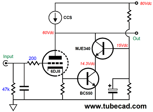
A one-tube per channel phono stage. One problem we face is that high-voltage transistors are not known for being quiet. A workaround would be to cascode two transistors, one low-voltage, low-noise transistor and one high-voltage transistor.
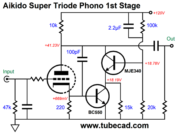
The bottom transistor is protected from high voltages by the transistor above it. If we wanted to use a plate resistor rather than the constant-current source, we must up the B+ voltage. In addition, we would have to provide a truly clean B+ voltage, as the plate resistor will allow power-supply noise to leak out, which the constant-current source would have blocked. One workaround would be to fancy and inject some Aikido mojo.
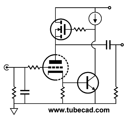
Note that the top resistor in the two-resistor voltage divider gets the bypass capacitor, not the bottom resistor. Also note the 15k emitter resistor that attaches where the two transistors meet. If we carefully select this resistor's value, we can create a power-supply-noise null at the output, as this resistor will see the full power-supply noise at its top lead and will prompt an anti-phase current variation that will force a power-supply noise null at the triode's plate. In place of the plate resistor, we could use another triode. The NPN transistor works into a constant-current source and feeds the top triode its input signal. This third active device moves the circuit out of the super-triode category into the Triadtron category
We use two NPN transistor in cascode, by the way. Another possibility would be to use an NPN transistor or MOSFET in place of the top triode. A low-input-capacitance MOSFET should be used.
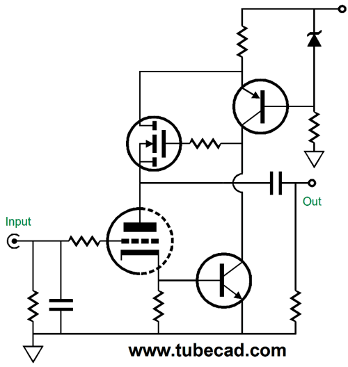
As I was looking at the schematic above, I asked myself How could I hotrod this circuit? The cascoded NPN transistor was obvious. Then it came to me: Why not drive the MOSFET's gate in a push-pull fashion?
The PNP transistor also monitors the current flow through the triode, but reacts in an anti-phase fashion relative to the NPN transistor at the cathode. The result is that when the triode backs of its conduction, the PNP transistor aggressively pulls up at the MOSFET's gate; when it conduction increases, the NPN transistor aggressively pulls down on the gate. At the sate time, the triode's plate is shielded from the power-supply noise. Is this perfection? I doubt it. In SPICE simulations, the SPICE engine ran slow and haltingly, when simulating the above circuit. Never a good omen. Moreover, the MOSFET's current conduction, like the triode's, is confined to its idle value. In contrast, in this earlier circuit, the MOSFET's current flow is free to vary as much as it needs to establish a fixed current flow through the triode. Still, this topology variation is interesting. Maybe, we could use only the top half, wherein the PNP transistor monitors the triode's current flow and its collector terminates into a constant-current source, while the triode's cathode resistor is bypassed with a large-valued capacitor (or even eliminated altogether and a battery is used to bias the triode's grid).
Music Recommendation: Jazz at the Pawnshop The album was recorded live and it sounds live, as in actually being performed in your living room live. Arne Domnerus is a well-established European jazzman and this album was recorded in 1976 in Sweden. Many consider it the best recorded jazz album ever. It might be, but it is not the best jazz album ever in terms of musical content, as too many American jazz greats fill the top 20 greatest jazz albums—if not top 100 albums. Still, Jazz at the Pawnshop is a fun listen. After you give it a listen, try his fine 2012 album, Antiphone Blues, a listen.
//JRB
User Guides for GlassWare Software
For those of you who still have old computers running Windows XP (32-bit) or any other Windows 32-bit OS, I have setup the download availability of my old old standards: Tube CAD, SE Amp CAD, and Audio Gadgets. The downloads are at the GlassWare-Yahoo store and the price is only $9.95 for each program. http://glass-ware.stores.yahoo.net/adsoffromgla.html So many have asked that I had to do it. WARNING: THESE THREE PROGRAMS WILL NOT RUN UNDER VISTA 64-Bit or WINDOWS 7 & 8 or any other 64-bit OS. I do plan on remaking all of these programs into 64-bit versions, but it will be a huge ordeal, as programming requires vast chunks of noise-free time, something very rare with children running about. Ideally, I would love to come out with versions that run on iPads and Android-OS tablets.
//JRB
|
|
John Gives
Special Thanks to the Special 66
I am truly stunned and appreciative of their support. In addition I want to thank
All of your support makes a big difference. I would love to arrive at the point where creating my posts was my top priority of the day, not something that I have to steal time from other obligations to do. The more support I get, the higher up these posts move up in deserving attention. Only those who have produced a technical white paper or written an article on electronics know just how much time and effort is required to produce one of my posts, as novel circuits must be created, SPICE simulations must be run, schematics must be drawn, and thousands of words must be written. If you have been reading my posts, you know that my lifetime goal is reaching post 1,000. I have 563 more to go. My second goal is to gather 1,000 patrons. I have 934 patrons to go. Help me get there.
Only $12.95 TCJ My-Stock DB
Version 2 Improvements *User definable Download for www.glass-ware.com |
||
| www.tubecad.com Copyright © 1999-2018 GlassWare All Rights Reserved |

