| John Broskie's Guide to Tube Circuit Analysis & Design |
|
22 October 2018 Post 443
Kick-Butt Ground-Grid Amplifiers
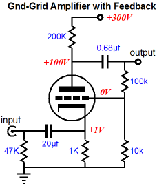
The cathode-coupled amplifier amplifier offered two big features: low input capacitance and no phase inversion at its output. If a grounded-cathode amplifier or an Aikido or SRPP gain stage were used instead, the inverted phase at the output would result in flipping the phase whenever gain was included. Not good. Now, we could easily live with with constantly flipped phase, as we only need to flip the phase at the loudspeaker's terminals. But we cannot live with a non-intentional phase flipping. Well, the other non-inverting tube-based gain stage is the grounded-grid amplifier.
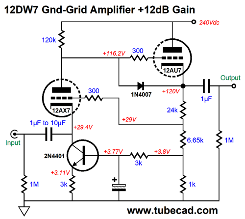
The downside to the grounded-grid amplifier is its low input impedance—we must drive the triode's cathode after all. One workaround is to use a triode with a high plate resistance and run it under a light idle current. The following grounded-grid amplifier makes use of a 12DW7/ECC832 twin triode tube that hold dissimilar triodes, effectively 12AX7 and 12AU7 triodes.
The input 12AX7 triode sees a constant-current source at its cathode, which helps raise its input impedance (about 27k). In addition, this constant-current source is also an auto-bias circuit. If the input triode is not drawing enough current, the NPN transistor's base will see a higher voltage, which will force its collector to draw more current. The transistor does not see audio frequencies at its base due to the RC filter formed by the 3k resistor and 1kµF capacitor, as this low-pass filter's transition frequency is far below 1Hz. The 3k and 1k resistors are effectively in parallel with each other, resulting in 750 ohms. This resistance must be added to the 6.65k bottom feedback resistor's value, making a total of 7.4k of resistance. In other words, the 24k and 7.4k resistances define a negative feedback loop that sets a gain of 4 (+12dB). Finally, the 1N4007 diode is there to protect the cathode follower triode at turn on, when the tube is cold and not conducting. Since we have introduced a hybrid element with the NPN-based constant-current source. Well, we can continue down this hybrid path. The following design uses a P-channel FET to drive the low-impedance cathode and still offer an ultra-high input impedance.
Note that FET's drain attaches to the -12V power-supply rail. Also note the large-valued cathode resistor, the result of the FET's source being at a negative voltage. Another possibility is to use a P-channel MOSFET in the FET's place.
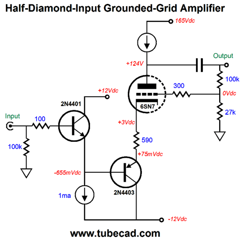
Unlike the P-channel FET, the MOSFET's source voltage is positive, which explains why the triode's plate voltage is higher and why no cathode resistor is used. In general, I fear the MOSFET's higher input capacitance, but after some SPICE simulations, with an IRF9510 and a 6SN7 models, I saw bandwidth out far beyond 100kHz. Nonetheless, we should strive to use a low-power MOSFET with a relatively low input capacitance. Another possible arrangement is to use a bipolar transistor stage to drive the triode's cathode. I tried several simple topologies and the best was the half-diamond circuit.
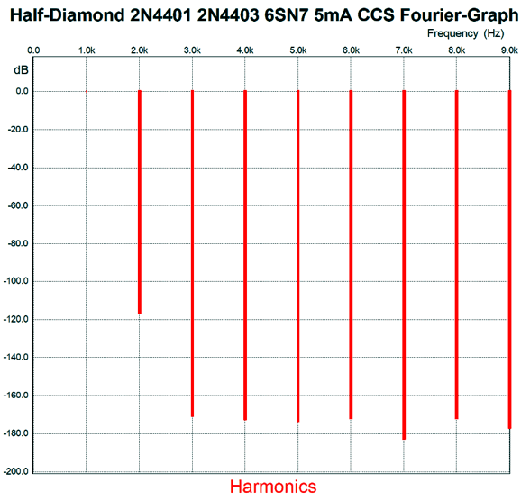
Anything more complex led to more distortion, a more push-pull-like distortion at that, while anything less complex led to a higher input impedance. Here is the SPICE-generated Fourier graph for 1Vpk at 1kHz.
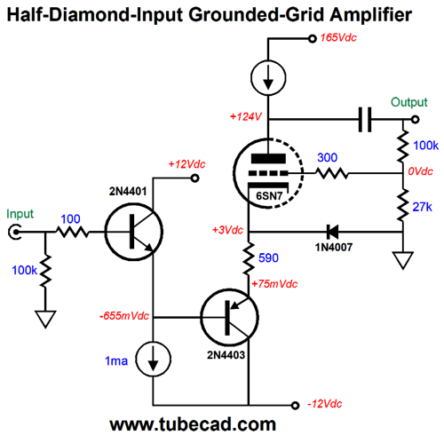
Note the amazingly low distortion and the primarily 2nd-order signature. The THD is insanely low, below 0.01%. Even if reality is ten times worse, the results are still amazing. What is missing is a protection diode.
The added 1N4007 diode only becomes forward biased when the 6SN7 triode is cold and yet to draw current. The constant-current source should be labeled with 10mA. Let's now move on to output stage, which is a fancy cathode follower that uses a single triode and no output coupling capacitor.
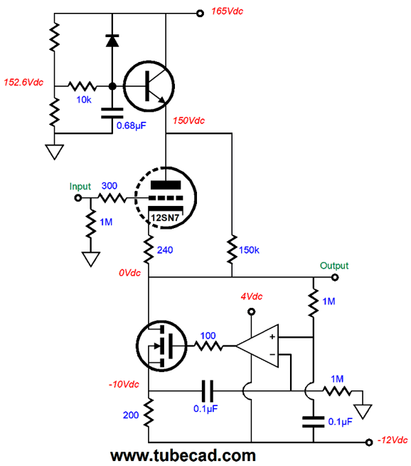
The cathode follower is loaded by a compliant-constant-current source (CCCS) that strives to eliminate any any DC offset voltage at the output and to establish an idle current set by the triode. The NPN transistor is configured as a simple capacitor-multiplier that filters the DC leaving its emitter. When loaded by a constant-current source, a cathode follower's PSRR is equal to the inverse of the triode's amplification factor (mu), i.e. 1/mu, or in dBs PSRR = 20Log(1/mu). In other words, we should provide a fairly clean B+ voltage. The 150k resistor is there to allow the CCCS to still maintain a 0Vdc output voltage at start-up or if the output triode is missing from its socket. Okay, let's start putting everything together.
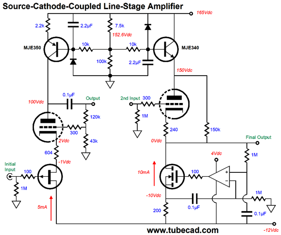
We see the MJE350 PNP transistor used in a constant-current source circuit, while the NPN MJE340 transistor works in a capacitor-multiplier circuit. What would the require power supply look like?
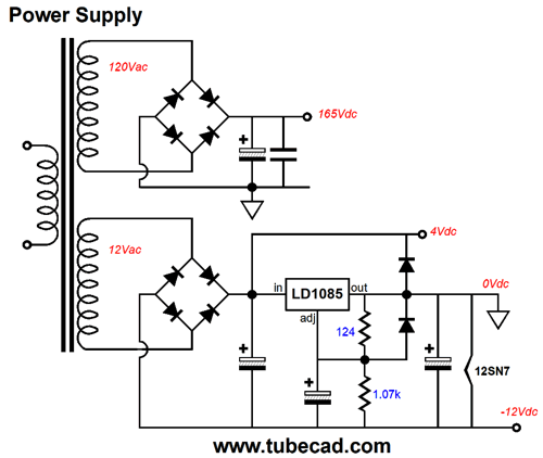
Note how a positive adjustable LDO voltage regulator is used to establish a regulated negative power-supply rail. Sneaky, isn't? Why not just use an LM337 negative regulator? We could, but then we would not get the free +4Vdc power-supply-rail voltage. I said it was sneaky. By grounding the positive regulator's output we create a regulated negative power supply. In addition, the 12SN7's heater attaches to the -12Vdc power-supply rail voltage. (Or, two 6SN7 heaters can be placed in series across the -12Vdc power-supply rail and ground.) The +4Vdc power-supply rail is needed due to most OpAmps not being able to accept an input voltage equal to or greater than their positive power supply voltage. Also note the relatively low B+ voltage of only 165Vdc. Of course, we could (and probably should) add at least an RC filter or LC filter. (If active circuitry was not used to establish the constant-current source and capacitor multiplier circuit, and if a plate resistor and passive RC filter were used in place the two active circuits, the B+ voltage would have to be much higher. How much higher? At least twice as high would be a good starting point.)
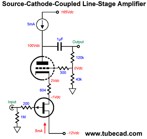
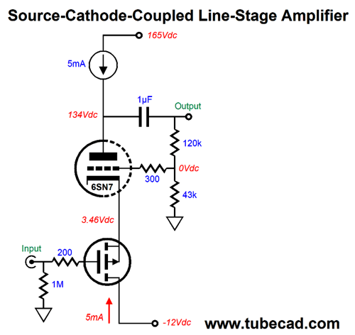
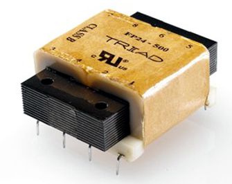
I would use a flat-pack power transformer with dual 120Vac primaries and dual 12Vac secondaries. The great advantage to the flat-pack design is that the secondary does not lie atop the primary, which results in far lower capacitance between windings. With this proposed power transformer, one primary winding could be used to create the B+ voltage and each heater element would get its own regulator. (This may not provide much benefit, as both negative regulators must still attach to ground.) Returning to the circuit, we could use an N-channel FET instead, which would make a source-cathode coupled amplifier.
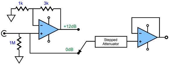
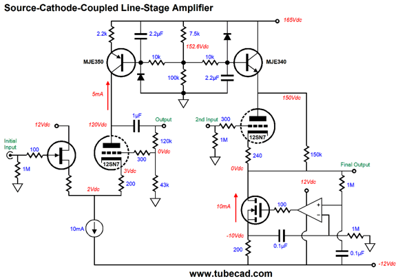
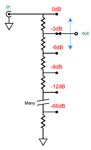
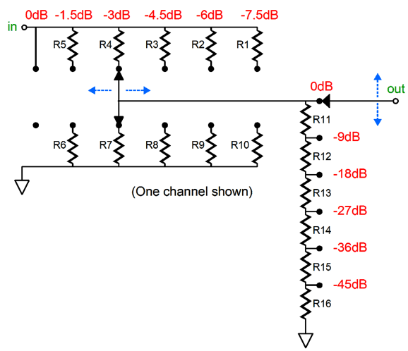
The FET acts much like a triode would in a cathode-coupled amplifier, but at a far lower B+ voltage, which in this example is merely +12Vdc. This will entail a different power supply topology, as the +/-12Vdc is best provided by a conventional bipolar power supply, with positive and negative regulators, i.e. an LD1084 and LM337. What I like about this design is its economy. Only one tube per channel. The kick-butt attribute results from using a stepped attenuator that would allow us to seamlessly switch in the gain stage when it is needed. Of course, if you are willing to do some extra work, you could use a regular audio-taper potentiometer as a volume control and use a switch to add or subtract gain as needed. To be frank, I have a hard time imagining any potentiometer, no matter how expensive, as being kick-butt. Ideally, true kick-butt would demand a ladder attenuator, not a series attenuator. What is the difference between the two types of stepped attenuators? Both attenuator types present a fixed input impedance and varying output impedance. Both provide precise, matched steps of attenuation. A series stepped attenuator, however, is similar to potentiometer made out of discrete resistors soldered in series. As we rotate the switch's shaft, we engage with a different nexus between two resistors in the long string. If the series attenuator hold 24 resistors, then 24 resistor will always be in the signal path, save for when no attenuation is applied and the knob is rotated fully clockwise.
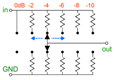
In contrast, a ladder attenuator is an array of many two-resistor voltage dividers, with only two resistor ever in the signal path. Obviously, this is much better, so why is so rare? Expense. Where a series attenuator would hold 24 resistors per channel and use a single deck per channel, a ladder attenuator requires 46 resistors per channel and two switch decks per channel.
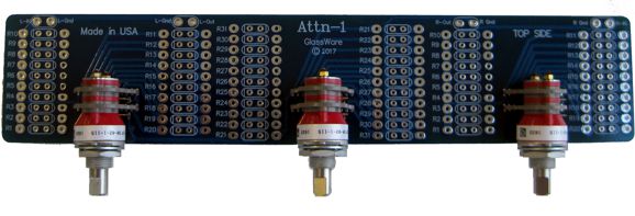
We can combine both attenuator types, which is what the GlassWare A3 and Attn-1 do.
For example, the A3 attenuator offers 36 steps of attenuation, but only hold six resistor in series in the series at portion and five pairs of two resistors in its ladder attenuator portion.
In contrast, a 36-position series attenuator would require 36 resistor soldered in series (that is a lot of solder joints); a 36-position ladder attenuator would require 70 resistors arranged in pairs (that is a lot of resistors).
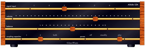
Out-of-the-Box Front Panel My own taste run to wood, glass, minerals, and metal. I would love to make an Aikido line-stage amplifier housed in a metal enclosure that was sheathed in wood, whose front panel would be a sheet of black glass that was striped by brass horizontal rods, which would pass through either wood or polished rock finger-holds, small triangular or rounded square pieces whose bottoms would be covered in black felt. As the finger-holds are slid back and forth across glass face-plate, the input signal source would be chosen, the balance set, the volume adjusted, the output coupling capacitor type selected, and the power engaged or shut off.
The magic behind the design is a black-masked printed circuit board below the glass face-plate, which would hold many reed relays.
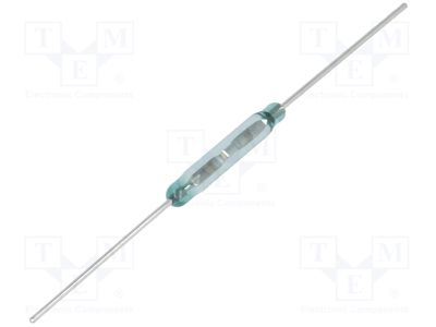
The reed switches are actuated by placing a magnet near them; and each finger-hold would hide a powerful magnet inside. With such a design, a ladder stepped attenuator could easily be implemented. The close spacing of the reed switches would provoke a natural make-before-break engagement of reed relays, so a smooth volume adjustment would result. Inside the enclosure, the vacuum tubes would reside. Round port holes at the sides would show the glow within. I once happened upon a website for accessories for yachts. Mercy. Many fancy and expensive hole trims were sold, along with many round, glass-filled port holes.
Music Recommendation: While My Guitar Gently Weeps
The second was Karen Mok, who is probably the famous person that I had never heard of before. As I learned from Google: "Karen Joy Morris, known professionally as Karen Mok, is one of the leading Hong Kong actresses and pop stars. She has won the Golden Melody Award three times, has released over 20 solo CDs, has acted in over 40 movies and has over 36 million followers on Chinese microblogging site Weibo." She has a lovely voice and the Chinese instruments add an interesting exotic flavor. Third cover that I recommend highly is by Martin Luther McCoy and his cover appears on the Across The Universe album. The album to the right is Blackbird - The Beatles Album by Milos Karadaglic. He can certainly play the guitar, but I will have to listen to his entire album before I can decide if he altogether suits me.
The cover on the album Pastor of Muppets by RawFilters Acoustic One caught me by surprise, as I expected a rap take on this classic song. I was majorly wrong. Deeply felt and moving is how I would describe their rendition. Wonderful. Also wonderful was the cover by Lohninger & Fischbacher on their album Soul Garden. Where RawFilters Acoustic One manage to instill some Johnny-Cash-like country mojo, Lohninger & Fischbacher transform the song into a jazz vocal piece.
Okay, I relented and I just gave him a listen. Not bad. He creates an almost lullaby mood. I cannot believe that I almost forgot to mention Jake Shimabukuro playing his ukulele on his album, Live In Japan. Truly fine.
We can go from Jake's four strings to by Fiona Hosford's 47 strings on her harp, which she plays on her album The Long Day Is Over. Equally lovely.
All of these performances are available at Tidal. //JRB
User Guides for GlassWare Software
For those of you who still have old computers running Windows XP (32-bit) or any other Windows 32-bit OS, I have setup the download availability of my old old standards: Tube CAD, SE Amp CAD, and Audio Gadgets. The downloads are at the GlassWare-Yahoo store and the price is only $9.95 for each program. http://glass-ware.stores.yahoo.net/adsoffromgla.html So many have asked that I had to do it. WARNING: THESE THREE PROGRAMS WILL NOT RUN UNDER VISTA 64-Bit or WINDOWS 7 & 8 or any other 64-bit OS. I do plan on remaking all of these programs into 64-bit versions, but it will be a huge ordeal, as programming requires vast chunks of noise-free time, something very rare with children running about. Ideally, I would love to come out with versions that run on iPads and Android-OS tablets.
//JRB
|
|
John Gives
Special Thanks to the Special 68
I am truly stunned and appreciative of their support. In addition I want to thank
All of your support makes a big difference. I would love to arrive at the point where creating my posts was my top priority of the day, not something that I have to steal time from other obligations to do. The more support I get, the higher up these posts move up in deserving attention. Only those who have produced a technical white paper or written an article on electronics know just how much time and effort is required to produce one of my posts, as novel circuits must be created, SPICE simulations must be run, schematics must be drawn, and thousands of words must be written. If you have been reading my posts, you know that my lifetime goal is reaching post 1,000. I have 557 more to go. My second goal is to gather 1,000 patrons. I have 932 patrons to go. Help me get there.
Only $12.95 TCJ My-Stock DB
Version 2 Improvements *User definable Download for www.glass-ware.com |
||
| www.tubecad.com Copyright © 1999-2018 GlassWare All Rights Reserved |





%20Cover.jpg)
