| John Broskie's Guide to Tube Circuit Analysis & Design |
18 February 2019 Post 456
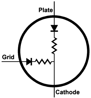
Positive Grids Z = (rp + Ra)/(mu + 1) Still, compared to a 16-ohm headphone, the usual audio triode, such as 6DJ8 or 6SN7 or 12AU7, presents an input impedance at is cathode at least ten times bigger than that 16-ohm headphone. For example, even a high-transconductance triode, like the 6DJ8, loaded by a 10k plate resistor presents cathode impedance over 300 ohms. (If a cathode resistor is used, then its resistance must be placed in parallel with the cathode impedance.) Well, all this got me thinking: what if the OpAmp, rather than drive the cathode, drove the grid. Don't grids present ultra-high impedances? They do, when negatively biased relative to the cathode. But when the grid becomes positive relative to the cathode, its impedance plummets, as the grid an cathode effectively define a diode and current flows from the cathode into the grid. How low is a grid's impedance when driven positively. Alas, it is hard to say, as few tube data sheets include this specification, the exception being the the data sheets for tubes that were expected to be used in class-A2 amplifiers, wherein the grid was purposely driven positive to yield the most output power possible, as class-A2 yields high current in spite of low plate voltages. Alas, No SPICE model that I have seen includes the aspect of a triode's sliding grid impedance.
Nonetheless, assuming that a triode's grid impedance does not exceeds its cathode impedance, the OpAmp should be up to the task. And even if the OpAmp isn't up to the job, we could add either a PNP transistor or N-channel MOSFET based follower to drive the grid. The question that you might be asking yourself is: if positive grid current flow is such a hassle, why not just avoid it altogether, just as most tube audio circuits do? The answer consists of two words: low voltage. Unlike solid-state devices, triodes depend on high voltages to deliver high currents. When do we need high current flow in an audio circuit? In general, we don't, unless we are driving headphones or loudspeakers. The usual solution is to use both high voltages and an output transformer, as the transformer will increase the current swings by the same ratio as it decreases the voltage swings.
The following design exploits the ease and low-cost of a 48V and 24V switching power supplies. Even a medical-grade switching power supply is relatively cheap compared to a single tube, such as a KT88.
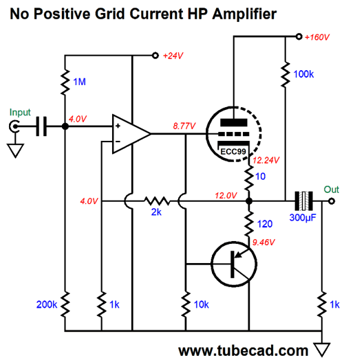
Positive-Grid Headphone Amplifiers Let's start with, however, a single ECC99 triode and PNP transistor and NO POSITIVE grid voltage.
Note that the grid is at 8.77V, while the cathode sits at 12V, a difference of -3.23V. The PNP transistor's emitter sits at 9.46V, while its base sees the same 8.77V that the grid sees. a difference of -0.69V. The ECC99's B+ voltage is a hot 160V and its idle current is a heavy 23.7mA, making for a plate dissipation of 3.5W per triode. Okay, now we will look at a POSITIVE grid version with the same triode and transistor.
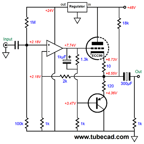
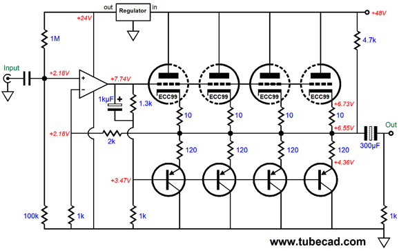
Note that the triode's grid is over 1V more positive that its cathode. Also note that the PNP transistor's base sees the same AC signal as does the grid, making this a push-pull output stage. Class-A operation will allow us to deliver twice the idle current into the load impedance. Of course, one triode will not draw that much current, even with positive grid voltage; in this example, the triode and transistor idle at about 18mA. Now, on the other hand, four triodes will bring the OPS idle current up to a robust 72mA, so peak current flows of 144mA would be possible, which implies peak voltage swings of 7.2V into a 50-ohm load and half a watt of power. Not bad for a 48V B+ voltage. In addition, the plate dissipation drops to only 0.75W per triode in this positive-grid version. Okay, let's flesh-out the design with the full complement of four triodes per channel.
Notice how the 18k resistor was replaced with a 4.7k resistor. This resistor gives the PNP transistors a current path to the B+ voltage even when the triodes are either cold or missing from their sockets. The OpAmp is in charge of the output, as its negative feedback loop extends to the output. The 2k and 1k feedback resistors set a gain of 3 or +9.5dB. The assumption being that the signal source offers at least 1Vpk of input signal. The transistors are MJE15033 types and the OpAmp could be any single or dual OpAmp that exhibits unity-gain stability (a gain of 3 is darn close to unity gain). I would use an OPA2107; in fact, that is the OpAmp that I used in SPICE simulations. Speaking of which, here is the current balance between triode and transistor, while delivering 1Vpk into 32 ohms.
As the load impedance rise, the balance falls away. Is this a problem? Not really, as the transistor reacts more strongly than the triode. Here is an example, with a load impedance nearly ten time greater, i.e. 300 ohms.
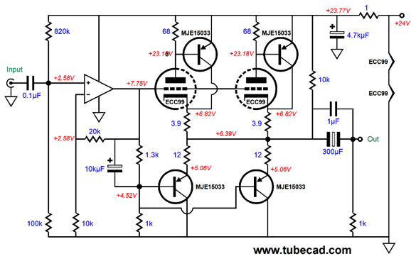
The next design is radically different in many ways. For example, the B+ is low 24Vdc throughout; the OpAmp's negative feedback loop does not extend to the output of the headphone amplifier; only two parallel triodes are used per channel; the triodes are configured in a compound arrangement with a PNP transistor at their plates. What didn't change is that the grids are positively biased.
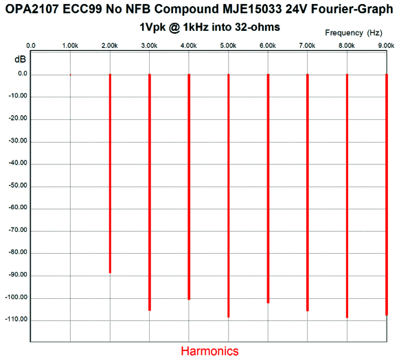
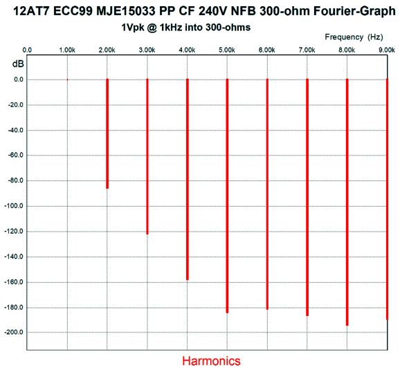
One JJ ECC99 is used per channel, i.e. two triodes per channel. The two heater elements are placed in series and attach to the 24Vdc B+ voltage. The output stage draws a heavy 220mA per channel, but the triodes idle at only 8.7mA. In SPICE simulations, the results were striking.
This is not what we see 99.999% of the time, as the odd harmonics are lower than the even harmonics. Look at 3rd, 5th, and 7th harmonics. Amazing. When I designed this hybrid headphone amplifier, I had 40-ohm headphones in mind, so that is where the best current swing balance obtains.
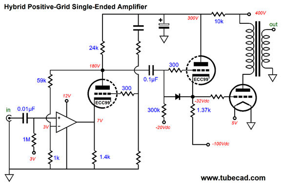
Positive-Grid in a Single-Ended OPS The big problem is that when the output tube's grid goes positive relative to the its cathode, it ceases to present an ultra-high impedance, which can result in blocking distortion if capacitor coupled. (Inter-stage transformer actually do not work as well as many imagine, as the transformer's secondary is usually coupled to a capacitor, so the problem ends up be passed off to another section of the amplifier, not eliminated.) The following design uses an OpAmp to drive a triode's cathode directly, while the output triode's grid is driven directly by a cathode follower.
Note how the OpAmp's negative feedback loop only extends to the driver triode's plate, not to the cathode follower's output. The Aikido mojo can only apply to the driver stage, as the OpAmp prevents it from extending to the amplifier output.
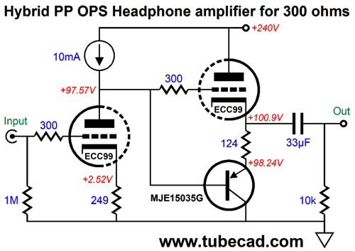
Negative-Grid Push-pull hybrid Output stage
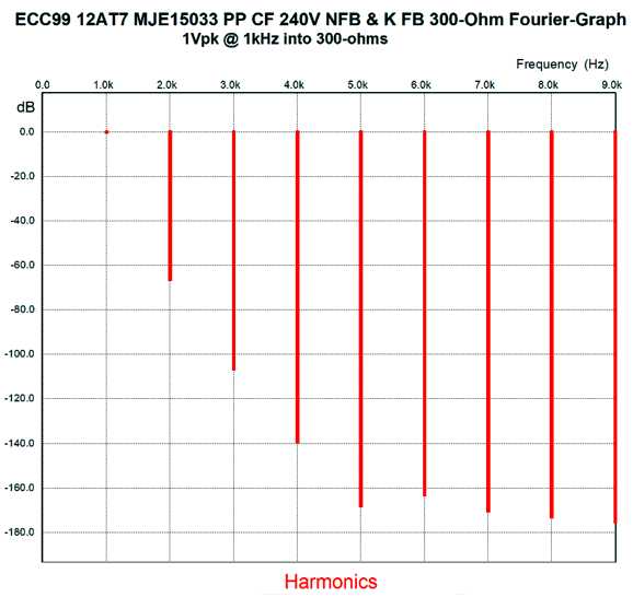
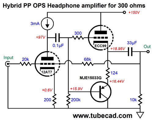
Shown above is a simple hybrid, push-pull headphone amplifier for 300-ohm headphones, such as made by Sennheiser and others. In general, the lower the headphone impedance, the smaller the voltage swings needed. Thus, when the signal source runs off batteries, 16-ohm headphones make sense, whereas 300-ohm types don't. For example, I have a new phone, a Sony, which surprisingly enough sounds good, but can only make my HD650 whisper. This circuit can deliver big voltage swings into the 300-ohm headphones, due to its push-pull output stage. The output stage must be run in strict class-A to get the lowest distortion, but it can be driven into class-AB if needed. The 124-ohm resistor between cathode and emitter equalizes the current swing from the dissimilar OpAmp devices; it also sets the output stage's idle current. No negative feedback loop is used. We can increase both the gain and the PSRR by replacing the plate resistor with a constant-current source.
In SPICE simulations, the PSRR went from -9.6dB to -33dB, while the output impedance remained constant at 57 ohms. With the plate resistor, the gain came in at 11.3 (+25.1dB) and the THD came in at a bit below 0.1%; with the constant-current source, the gain was 18 (+34dB) and the THD was also a bit below 0.1%, oddly enough. All in all, a fun circuit. For me, however this headphone amplifier offers too much gain, as something closer to just 3 would be ideal to make my phone roar while I listen to Tidal. What to do? We could replace the input triode with a low gain triode, but the ECC99's amplification factor was already fairly low, coming in at 22. A 12AU7's mu of 17 would only help a little. The other workaround is to apply a negative feedback loop.
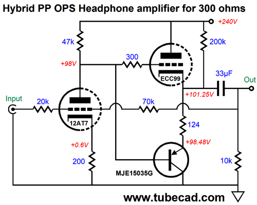
The input triode has been replaced by a 12AT7 and the 20k and 70k feedback resistors set a gain of 3, +9.5dB. The 200k resistor is important and should have appeared in the prior schematics, but I didn't want to overwhelm. This resistor provides a current path to the B+ voltage when the input tube is either cold or missing from its socket or suffers from an open heater element. Here is the results from SPICE.
The THD is less than 0.01%. Of course, we could replace the plate resistor with a constant-current source. Instead, I want to inject some positive feedback to force a more tube-like sound on the headphone amplifier.
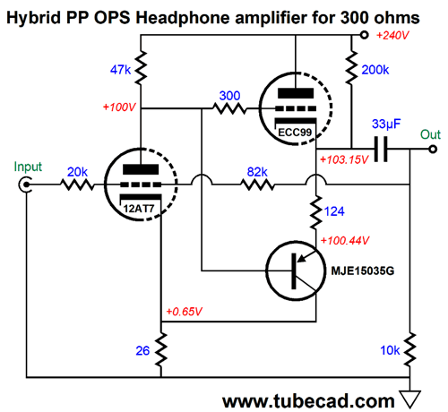
Note that the PNP transistor's collector terminates into the 12AT7's cathode, not ground, which explains the cathode resistor's low value of 26 ohms. In SPICE simulations, the results were interesting.
The THD is less than 0.1%, which is worse than the previous version, but may sound better to your ears, due to output impedance being ten times greater, 60 ohms versus 6 ohms. The higher output impedance will result in fatter bass response. Another possible variation is to run a lower B+ voltage and add an internal coupling capacitor.
I know that most tube-loving folk will be scratching their heads right now, as the circuit seems to missing a resistor, a resistor that would span from the B+ voltage down to the 200k resistor. This missing resistor isn't needed, as the PNP transistor's base draw current, so that current flow against the 200k resistance creates a 15.9V voltage drop. In this variation the ECC99 still draws 22mA and dissipates 2.9W per triode, but the PNP transistor's dissipation falls dramatically; so much so that a heatsink may not be needed, as it heat dissipation at idle is less than half a watt. Note the absence of the current-path resistor that attaches to the B+ voltage; it is no longer needed, as the internal coupling capacitor prevents the EC99's grid from seeing B+ voltage at start-up. Okay, John, all of this is great, but I own 50-ohm headphones, not 300-ohm types. Well, the obvious workaround would be to use many more ECC99 tube's in parallel. Or we could get sneaky. For example, what if we boost the ECC99 triode's output with an IMC, an impedance-multiplier circuit?
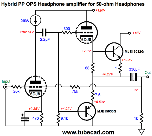
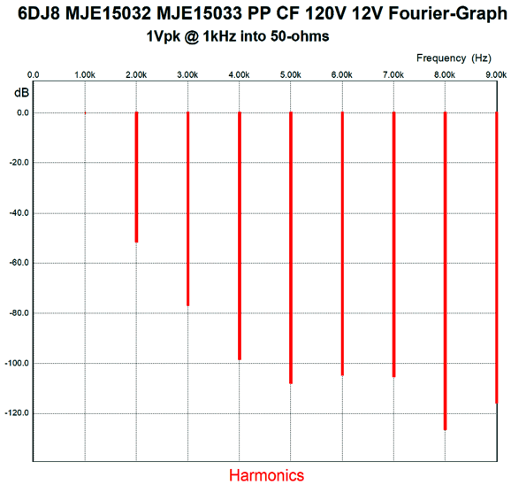
Much as changed in this variation. For example, 6DJ8 triodes are used throughout. The added NPN transistor is under 6DJ8 triode's control; in turn, the triode runs under a near constant-current draw. Note the 2.2µF internal coupling capacitor, which is needed to overcome the 9.1k grid-base resistor. The 12Vdc power-supply rail can be used to power the 6DJ8 heater elements. The top NPN transistor idles at 87mA, so the implication is that a class-A window of +/-174mA is possible, which into a 50-ohm load implies 750mW of power and 8.7Vpk voltage swings, which simply cannot occur, due to the 7.5-ohm emitter resistor and the 12V power supply. Realistically, 4Vpk output voltage swings set a truer limit. In SPICE simulation, the 4Vpk into 50 ohms resulted in 1% THD. Here is the results with only 1Vpk.
If I were to build the above circuit, I would probably replace the 9.1k resistor with a constant current source and I would add an OpAmp to force the output to center at 6Vdc.
Music Recommendation: A Mix of Blues and Jazz
Keith Richards' Crosseyed Heart album definitely belongs in the blues section of the record store. It sounds very much like The Stones and not like them. It's an interesting album, as it sounds like it was casually thrown together in a week. Not that the sound isn't a high-production effort, it is. It's just that it sounds rather spontaneous and easy-going—the very opposite of belabored. There's even a duet with Norah Jones, Illusion. In contrast, R.L. Burnside's was a Black American blues singer who died in 2005 (born 1926). His singing and guitar playing are pure country Delta juke-joint blues. His Wish I Was in Heaven Sitting Down album is odd, as it is an excellent showcase for his voice, but is marred by the inclusion sampling and scratching—no doubt forced on the recording in a desperate attempt to garner younger listeners—only distracts. Most 20 year-olds would sooner drink Geritol than listens to a 73 year-old man sing. As a friend of mine would put it, What the F were they thinking? Nonetheless, the album is worth a listen.
A French reader recommend the German jazz pianist Nils Frahm's new album, All Melody, to me. I am glad he did. At times, this album sounds closer to classical music than jazz. (I recognized the cover, but I don't know where I saw it before; perhaps, in an audio magazine review.) The last album, Reflections and Odysseys, by Rymden, Bugge Wesseltoft, Magnus Öström, and Dan Berglund, is another compelling example of Euro Jazz. (It took me two listens before I fell in love with the album.) As always, all four albums are available at Tidal. PS Right now I am listening to The Oracle by Angel Bat Dawid. She has produced a fascinating album, but I am not sure what I will think of it next week. Right now, however, I find it compelling.
//JRB
User Guides for GlassWare Software Since I am still getting e-mail asking how to buy these GlassWare software programs:
For those of you who still have old computers running Windows XP (32-bit) or any other Windows 32-bit OS, I have setup the download availability of my old old standards: Tube CAD, SE Amp CAD, and Audio Gadgets. The downloads are at the GlassWare-Yahoo store and the price is only $9.95 for each program. http://glass-ware.stores.yahoo.net/adsoffromgla.html So many have asked that I had to do it. WARNING: THESE THREE PROGRAMS WILL NOT RUN UNDER VISTA 64-Bit or WINDOWS 7 & 8 or any other 64-bit OS. One day, I do plan on remaking all of these programs into 64-bit versions, but it will be a huge ordeal, as programming requires vast chunks of noise-free time, something very rare with children running about. Ideally, I would love to come out with versions that run on iPads and Android-OS tablets.
|
Special Thanks to the Special 77
I am truly stunned and appreciative of their support. In addition I want to thank
All of your support makes a big difference. I would love to arrive at the point where creating my posts was my top priority of the day, not something that I have to steal time from other obligations to do. The more support I get, the higher up these posts move up in deserving attention. Only those who have produced a technical white paper or written an article on electronics know just how much time and effort is required to produce one of my posts, as novel circuits must be created, SPICE simulations must be run, schematics must be drawn, and thousands of words must be written. If you have been reading my posts, you know that my lifetime goal is reaching post 1,000. I have 544 more to go. My second goal is to gather 1,000 patrons. I have 923 patrons to go.
The Tube CAD Journal's first companion program, TCJ Filter Design lets you design a filter or crossover (passive, OpAmp or tube) without having to check out thick textbooks from the library and without having to breakout the scientific calculator. This program's goal is to provide a quick and easy display not only of the frequency response, but also of the resistor and capacitor values for a passive and active filters and crossovers. TCJ Filter Design is easy to use, but not lightweight, holding over 60 different filter topologies and up to four filter alignments: While the program's main concern is active filters, solid-state and tube, it also does passive filters. In fact, it can be used to calculate passive crossovers for use with speakers by entering 8 ohms as the terminating resistance. Click on the image below to see the full screen capture.
Tube crossovers are a major part of this program; both buffered and un-buffered tube based filters along with mono-polar and bipolar power supply topologies are covered. Available on a CD-ROM and a downloadable version (4 Megabytes). |
||


| www.tubecad.com Copyright © 1999-2019 GlassWare All Rights Reserved |