| John Broskie's Guide to Tube Circuit Analysis & Design |
14 June 2019 Post 468
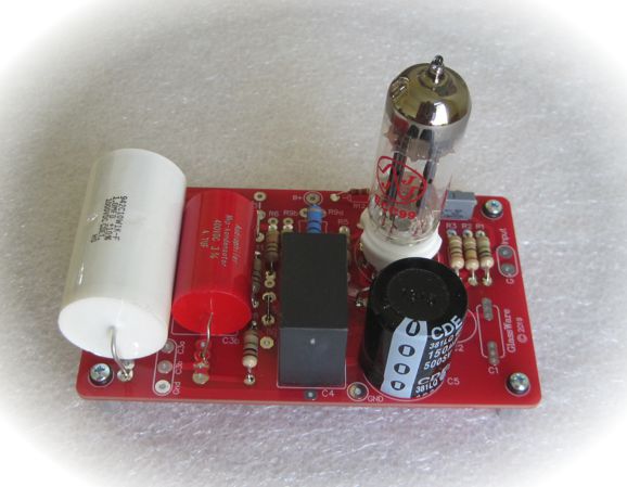
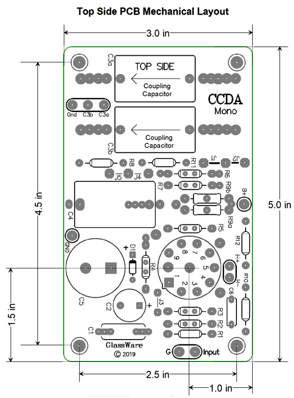
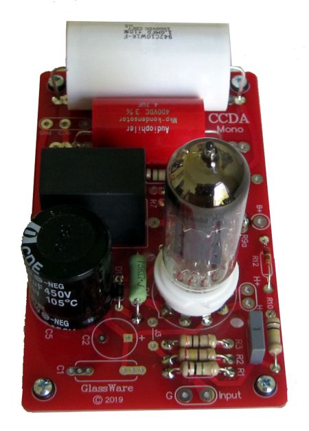
New CCDA Mono Noval PCB At first, going with point-to-point wiring seemed the best solution to building my truly minimalist line-stage amplifier. I own dozens of 12J5 single-triode tubes (one half of a 6SN7) and my Octal Universal PCB seemed a natural pairing. Unfortunately, high-quality parts means big parts. The more I thought about it, the less I liked the idea of going point-to-point. My solution was to create a new PCB: the CCDA Mono Noval. The PCB is cute, being only 3 inches by 5 inches big. The PCB holds one CCDA (Constant-Current-Draw Amplifier) gain stage and one RC B+ voltage filter and two output coupling capacitors.
The CCDA Mono Noval is a mono design, so two will be needed for stereo. Why mono? Flexibility ranks first. Some actually run mono systems. Others want to make dual mono line stages, which use two separate enclosures and power supplies. A few will want to build mono-block single-ended power amplifiers. The list goes on... For me, I wanted to be able to place each tube far apart on the chassis, which a single PCB would not allow.
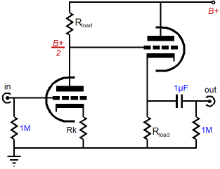
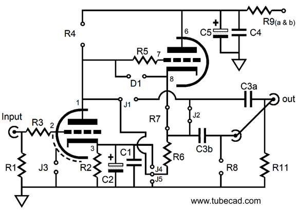
My idea here is the smaller enclosure would house only the IEC 3200AC power receptacle and power transformers and AC power switch. The PS-21 and two CCDA Mono Noval PCBs would sit inside the bottom enclosure. The CCDA gain stage is simple enough: a grounded-cathode amplifier develops gain and a cascading cathode follower buffers the output. The constant-current-draw feature results from each triode working in voltage phase, but in anti-current phase, so the sum of currents remains constant. Is that desirable? Indeed, as the B+ voltage is no longer banged about by the AC signal, which nicely sidesteps the issue of the RC capacitor having to shunt away the AC signal to ground. In other words, the power-supply capacitors have less work to do. Ask yourself this question, would you use an electrolytic power-supply capacitor as an output coupling capacitor? No, nor would I.
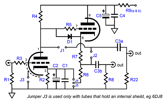
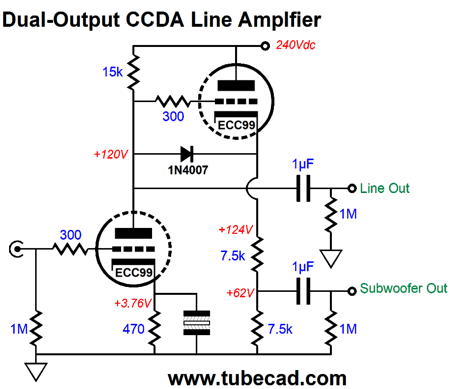
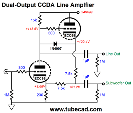
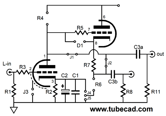
The grounded-cathode amplifier delivers a gain equal to Gain = muRa/(Ra + rp) Where the cathode resistor is bypassed by a large-valued capacitor and Ra is the plate resistor and rp is the triode's plate resistance. If the cathode resistor is unbypassed, the gain and PSRR drops and the output impedance increases. Here is the formula: Gain = muRa/(Ra + rp + [mu +1]Rk) Where the Rk is the cathode resistor; mu, the amplification factor. The cathode resistor and plate voltage set the idle current for the triode: the larger the value of the cathode resistor, less current; the higher the plate voltage, more current. The formula for setting the Iq is both simple and fairly accurate: Iq = B+ / (Ra + rp + [mu + 1]Rk) So, for example, a 6CG7 in a CCDA with a B+ voltage of +300V and 860 cathode resistors will draw 300/(30k + 6.5k + [2 + 1]860) amperes of current, or about 5.5mA. But in the CCDA, the input triode’s cathode resistor must do more than just set the idle current: it must also set the plate voltage to half that of the B+ voltage. So we must work backwards from the B+ voltage and the plate resistor’s value to zero in on the correct cathode resistor value. For example, assuming a 6SN7 triode and final B+ voltage of 250Vdc and a plate resistor value of 20k, we know that half the B+ is equal to 125Vdc, which divvied by the 20k plate resistor equals an idle current equal to 6.25mA. Now, we must find the cathode resistor value that will ensure the halving of the B+ voltage. Fortunately, a simple formula gets us close: Rk = (Ra - rp) / (mu + 1) Thus, in this example, using the tube manual’s specifications of a mu of 20 and an rp of 6.5k, Rk should equal 643 ohms.In fact, this resistor will result in too little current being drawn, resulting in a plate voltage 15V too high; and the empirically derived value is closer to 430 ohms. The alternative to formulas is to inspect the triode's plate curves, but some math will still be needed. The CCDA Mono PCB holds two output coupling capacitors. If you have read my previous posts, you know that I like having the option of choosing between the two sonic flavors provided by two dissimilar coupling capacitors. Few, share my preference, however, but many do like having the option of a bypass coupling capacitor built in to the PCB. Well, with this new CCDA PCB, we have a new option. Coupling capacitor C3a can either be placed in parallel with coupling capacitor C3b or it can attach to grounded-cathode amplifier's plate, not the cathode follower's output. This is a cool option. How so? We can choose between grounded-cathode amplifier or cathode follower outputs. We can use both, with the grounded-cathode amplifier output going to our main power amplifier and the cathode follower output going to the subwoofer amplifier.
In fact, we could use a smaller-valued coupling capacitor to insert a high-pass filter, say at 100Hz for use with a satellite loudspeaker, while a large-valued coupling capacitor would attach to the a subwoofer amplifier. Many tube power amplifiers, however, require a bigger input signal than the typical solid-state power amplifier. With my own system, the subwoofer amplifier only needs half the signal that my single-ended tube power amplifiers require, so I always use a second set of output RCA jacks that hold -6dB two-resistor voltage dividers. Well, I could impose this same -6dB attenuation on the cathode follower's output by using two equal-valued cathode resistors in series.
Note how the two 7.5k cathode resistors sum to 15k, which is the grounded-cathode amplifier's plate resistor value. We can also try the positive-feedback version.
After I had laid out the new CCDA Mono PCB and they arrived in my hands, I realized that I could hack the PCB to create either an SRPP or a Vogel "Aikido" topology.
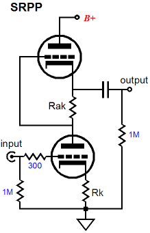
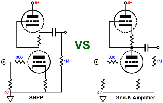
We all know the SRPP, so I won't go into all the details. The SRPP topology can make a sweet little headphone amplifier, as it offers large output swings into fairly low impedance loads—without a global feedback loop. Because even the lowest rp triode exhibit a relatively high plate resistance compared to the load presented by even high-ohmage headphones, it is best to use an output transformer with loads below 250 ohms.
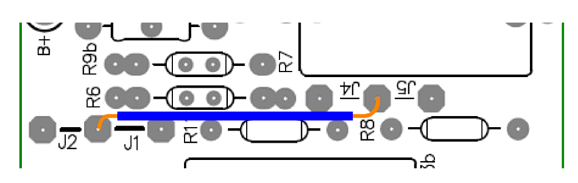
To hack an SRPP we use jumper J2 and omit resistor R4 & R8 and use a jumper wire for R7.
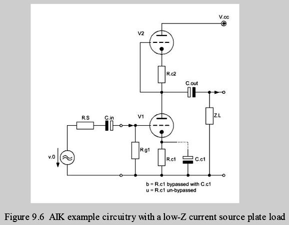
An additional jumper wire must be used to connect the bottom of R6 to the pin-1. Resistor R6 is the current-sense resistor, whose value (with a load impedance greater than zero) is found with the formula: R7 = (rp + 2Rload)/mu In fact, we can create an SRPP+, wherein two cathode resistor are used. See post 173 for more details. In his excellent book, How to Gain Gain, Burkhard Vogel displays his own "Aikido" gain stage, which uses a constant-current source load on a grounded-cathode amplifier. (Vogel quotes me—but not by name—in his dedication page, along with Albert Einstein.) One variation he outlines is the simple symmetrical grounded-cathode amplifier that replaces the plate resistor with an active load consisting of a triode and cathode resistor.
By using a bypassed cathode resistor on the bottom triode, the circuit realizes a much improved PSRR over the un-bypassed version. It looks a bit like an SRPP, but it is strictly single-ended in operation, with no pushing or Pulling.
By the way, I covered the topology back in 2002. The CCDA Mono PCB can be configured in this topology. Omit resistor R4 and R6 and diode D1. Use jumpers J1 and J2. Cathode resistor R2 and R7 need not be the same value, but usually are.
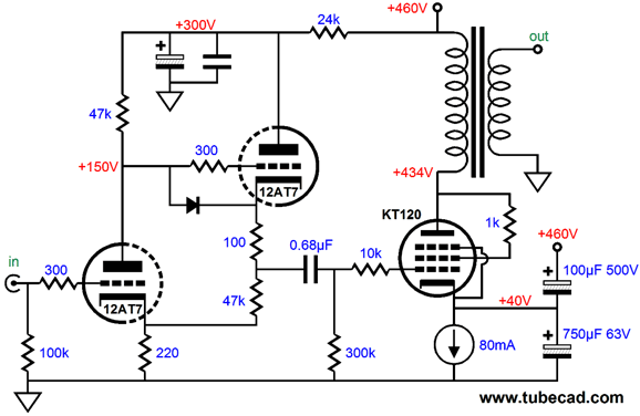
No doubt, some will use the new CCDA Mono as the frontend of their single-ended power amplifier. With the ability to inject positive feedback in the CCDA gain stage, we can get more gain than the triode's amplification would seem to imply being possible.
See post 260 for more information. I can easily imagine dozens of potential audio projects, such an active tilt-control:
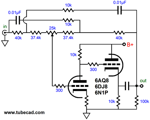
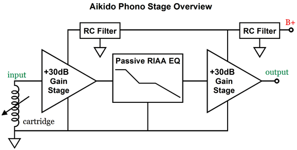
See post 266 for more details. Or, how about a phono preamp that uses two CCDA Mono gain stages per channel, with passive LCR equalization in between.
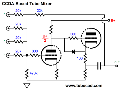
Or, maybe a tube mixer:
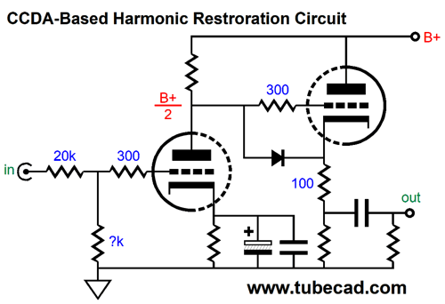
Four inputs are shown, but fewer or more are also possible. The feedback loop establishes unity-gain output. Speaking of unity-gain, why not a CCDA-based harmonic restoration circuit?
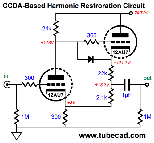
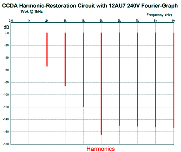
All we have to do is select the right resistor value for the bottom resistor in the input attenuator that undoes the CCDA's gain, so we get unity-gain output, but with enriched harmonic content. Imagine this circuit in series with a CD player's output. Actually, this circuit might not go far enough. In SPICE simulations with a 12AU7 model, the THD was only 0.1%. Here is a riper version.
The THD is not that much higher, dang. Still, I would love to hear what it does to a CD player or a DAC's output signal. Perhaps a 6N1P would prove the better tube to use.
Okay, I am sure you get the idea: there are plenty of possible uses for this new PCB.
The CCDA Mono Noval PCBs and part kits are available now at my GlassWare store. The PCB comes with a 20-page user guide.
Using 4-Ohm and 8-Ohm Speaker Drivers SPL stands for sound pressure level and is the common measure of a speaker driver's efficiency. Just about every 8-ohm driver's SPL is specified at a distance of one meter with 2.828Vrms (4Vpk), which equals 1W of power into an 8-ohm resistance. No problems here. In contrast, 4-ohm drivers can either be measured with 2Vrms (2.828Vpk) or with 2.828Vrms (4Vpk), which is a dang shame, as 2.828Vrms across a 4-ohm resistance equals 2W, not 1W, making for a false +3dB boost in SPL. The workaround is to carefully read the driver's specification sheet. If the test was held with 2.828Vrms and not 2Vrms, then subtract 3dB from the specified SPL to get the 1W SPL for the 4-ohm driver. For example, a 4-ohm woofer specified as delivering an SPL of 91dB with the 2.828Vrms test, will produce 88dB with one watt of input power. Imagine that you wish to build a D'Appolito loudspeaker configuration (aka, MTM layout), wherein a tweeter sits between two woofers. Also imagine that your goal is an 8-ohm speaker and that you plan on using two 4-ohm woofers in series and one 8-ohm tweeter. If the tweeter's SPL is 90dB, what should the two woofer's SPL be? 90dB? 87dB? Or something else? Since the tweeter was measured with 2.828Vrms (4Vpk), let's apply this same voltage to the two 4-ohm woofers in series, so each woofer sees 1.414Vrms (2Vpk), which is 0.707 as much voltage as the 2Vrms test voltage for 4-ohm drivers, so each driver experiences a -3dB attenuation. But at the same time, we have two woofers putting out equal sound pressure, so we gain +6dB, making a net +3dB increase over a single 4-ohm driver's SPL. Thus, we would need 4-ohm woofers with an SPL of 90dB - 6dB + 3dB or 87dB. On the other hand, if the 4-ohm woofers were measured with 2.828Vrms, their SPL would have to 3dB greater to make up for the cheating test voltage, so 90dB. Note that each woofer experienced half of the test voltage and thus incurred a -6dB attenuation, but due to twice the surface area radiating sound, they sum to +6dB. What about using two 16-0ohm woofers instead? Now, we face the potential problem of the SPL being under reported. For example, here are the specifications for a Dayton Audio 16-ohm driver.
The mistake is that 2.828Vrms only equal 1/2W into a 16-ohm resistance. In other words, the SPL would be 3dB greater with 4Vrms, bring the actual 1W value up to 83.2dB. Although 83.2dB still seems woefully inefficient, understand that two such drivers in parallel would equal 8 ohms and the SPL would increase to 85.2dB with 2.828Vrms, which is respectable. Note that the required SPL for pairing two 16-ohm woofers with a 90dB 8-ohm tweeter would be 87dB at 1W/1M. By the way, when we encounter the wrong test AC voltage used to specify a 4-ohm driver's SPL, many will assume malice, as the resulting specified SPL will prove too high. But with the same wrong test voltage being used to test 16-ohms drivers, what can we assume? Surely not malice, as the SPL is under reported, not over reported. Perhaps, stupidity? I believe both assumptions are wrong, as the most likely culprit is laziness. Imagine you are tasked with measuring the SPL of dozens of drivers. The smart thing would be to test all 4-ohm drivers, then all 8-ohm drivers, and then all 16-ohm drivers. This procedure would require only three one-time changes in AC test voltage, 2Vrms, 2.823Vrms, and 4Vrms. Instead, the lazy thing to do would be just to use 2.828Vrms throughout all the tests, as most drivers are 8-ohm types and you might have to test the drivers in order of the model number, not the impedance. Switching AC voltages over and over again would prove tiresome and you may not have even thought out what 1W at 1M means. Dante was wise in adding sloth (laziness) to his list of seven deadly vices. Okay, let's say we wish to use a 4-ohm tweeter, such as the planar and Heil AMT (Air Motion Transformer) types, with two 8-ohm woofers. The 4-ohm AMT puts out 94dB with 1W at 1M, which implies a test voltage of 2Vrms. Since both 8-ohm woofers will see 100% of the applied voltage, we gain 6dB in efficiency, but as 2Vrms is 0.707 as much voltage as 8-ohm-driver test voltage of 2.828Vrms, the nominal SPL must be reduced by 3dB, bringing the total for both woofers up by 3dB. In other words, 91dB 8-ohm woofers would match the 94dB ATM tweeter.
What if we used a typical 90dB, 4-ohm dome tweeter instead? All the previous math still holds and the result only differs by the difference in SPL (4dB), so the 8-ohm woofers would need to be 87dB 1W/1M types. Okay, returning to the 94dB AMT tweeter, what if we rather not deal with a 4-ohm loudspeaker? For example, say we own an OTL power amplifier that can barely handle 8-ohm loads or we own a solid-state power amplifier that just sounds harsh with 4-ohm speakers. By the way, solid-state amplifier sounding worse with 4-ohm loads is common. I discovered this the hard way 35 years ago. I owned a pair of the famous Strathern ribbon mid-tweeters with a 0.5 ohm impedance. They came with a step-down audio transformer, so the amplifier worked into an 8-ohm load. I measured the winding ratio and found it to be 4:1, which implied an impedance ratio of 16:1, which made the 0.5-ohm ribbon appear as 8 ohms to the amplifier. This got me thinking: why not build a solid-state power amplifier that was designed to drive a 0.5-ohm load? Since the audio transformer's winding ratio was 4:1, I could just quarter an existing solid-state design's power supply voltages, say +/-8Vdc rather than +/-32Vdc. I knew that an 6Vpk voltage swing would require 12A of current swing, so I should double the number of output transistors. By the way, 6Vpk would equal 36W of power into a 0.5-ohm load. So, how did it sound? Terrible, just terrible.
What went wrong? I had used regulated +/-15Vdc power-supply rails for the input and driver stages. I used high-quality parts throughout. I had doubled the number of output transistors and even hand-matched the current gains. In fact, I had even doubled the output stage idle current from 100mA to 200mA. It wasn't enough. What I failed understand was that gm-doubling distortion would prove 16 times worse with a 0.5-ohm load. In addition, I discovered that speaker cable resistance and terminal resistance made a big difference. In fact, I could hear the ribbon volume increase as I tightened the cable termination with a socket wrench. I should have quadrupled the number of output transistors and increased the idle current by at least eightfold. Ideally, I should have gone all out and built a class-A power amplifier that dissipated 100W of heat at idle and put out 32W of power, as that would have nicely sidestepped the gm-doubling issue. Okay, we return to the problem of not wanting to build a 4-ohm loudspeaker. One workaround would be to place a 4-ohm resistor in series with the 4-ohm AMT tweeter, which would create an 8-ohm load impedance and subtract 3dB from the AMT's 94dB SPL, resulting in 91dB. Finding a single 8-ohm woofer with an SPL of 91dB is not impossible. What if we want to use the D'Appolito configuration, but retain an 8-ohm load impedance? We have at least two options: two 16-ohm woofer in parallel or two 4-ohm woofers in series. The target SPL from the two woofers is 91dB, so we match the AMT tweeter's output.
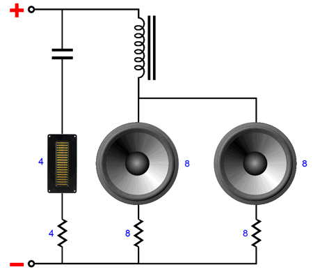
If we go for the two 16-ohm woofers, we have to dock 3dB from their SPL rating as 16-ohm drivers with 1W at 1M; but as we have twice the radiating surface area, we gain 6dB, making a final increase of 3dB. Thus, we would search for 88dB 16-ohm woofers.
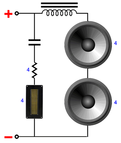
If we go for the two 4-ohm woofers, we have to also subtract 3dB from SPL rating as 4-ohm drivers, if the specification was found with 1W at 1M. If the rating came from 2W at 1M, i.e. 2.828Vrms, then we subtract 6dB; thus we find 91dB 4-ohm woofers whose SPL reflects 2W at 1M. Note that by forcing an 8-ohm impedance, we only lost 3dB. Another possible arrangement would be to use two 8-ohm woofer, but with an 8-ohm series resistor for each woofer. Why? The series resistance will increase the Qts of the driver, making the woofer more suitable for dipole use. Most HiFi woofers exhibit a Qts below 0.5, usually far below, which is okay when the woofer is used in either a sealed box or a ported enclosure, as the Qts will rise dramatically. With a dipole loudspeaker, however, the low Qts results in poor bass response. A critically damped woofer offers a Qts of 0.5; a punchy woofer offers something closer to a Qts of 1.
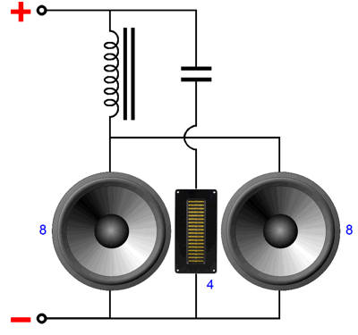
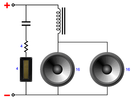
Since each 8-ohm woofer sees only half of the available voltage, we incur a loss of 6dB; but as we have doubled the emitting area, we gain 6dB; thus no change in SPL, paradoxically enough. Thus, what we would the need are two 91dB 8-ohm woofers in this arrangement. Is there no way to retain the AMT's full 94dB of efficiency and still present an 8-ohm load? There is, but few will like it: we can use an audio transformer with a winding ratio of 1.414:1, so the 4-ohm AMT tweeter appears as an 8-ohm load to the power amplifier. Other that the problem of no one making such a transformer, this solution is elegant. Because the bandwidth need only extend down to about 1kHz, the transformer would be quite small and, thus, could use premium core material. One potential danger would be that its primary DCR would be so low that any DC offset on the power amplifier's output could result in overheating the output stage or saturating the transformer core. The obvious workaround would be to place a crossover capacitor on the primary side. If we could actually find such a transformer (I do own two of them), then we would need either two 16-ohm drivers or or two 4-ohm woofers with 91dB SPLs. Still another possible setup would be to take advantage of a tube power amplifier's output transformer with many impedance taps. Many output transformers offer 16, 8, and 4-ohm output taps on the secondary. We could attach the 4-ohm AMT tweeter to the 4-ohm tap and two 8-ohm woofers in series to the 16-ohm tap.
As far as the tube output stage is concerned, the load is the same as if an 8-ohm woofer were attached to its 8-ohm tap. One watt at 10kHz would yield 94dB at one meter from the tweeter and 1W at 100Hz would also produce 94dB from the two 91dB woofers. How do we know that? One watt into 4 ohms requires 2Vrms. Since the 16-ohm transformer tap puts out twice the voltage as the 4-ohm tap, 4Vrms must appear at the 16-ohm tap. Each woofer sees half of the 4Vrms, yielding 2Vrms per woofer, which is 0.707 as much as is need for one watt into 8-ohms, so each woofer gets 1/2W of power, causing a -3dB drop in efficiency, producing 88dB from each woofer. We add our 6dB bonus from doubling the radiating surface area with two woofers and get 94dB. One downside to this arrangement is that the 16-ohms presented by the woofers requires twice the inductance that an 8-ohm impedance would; and the 4-ohm tweeter requires twice the capacitance that an 8-ohm tweeter would need for the same crossover frequency. In contrast, if we used a 16-ohm tweeter and a 4-ohm woofer with the same output transformer arrangement, the crossover parts values would quarter. For example, where the 4-ohm tweeter needs a 10µF capacitor to crossover at 4kHz, a 16-ohm tweeter only needs 2.5µF; where a 16-ohm woofer requires 0.64mH, a 4-ohm only needs 0.16mH for the same 4kHz crossover. Think about it: by reducing the crossover part values by four, we can now entertain buying air-core inductors and Mundorf capacitors. For example, a Mundorf 2.7µF Silver-Oil capacitor cost only $88.60, whereas a Mundorf 10µF Silver-Gold-Oil capacitor cost $277.10.
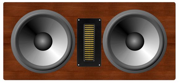
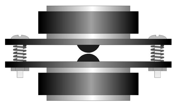
Why two tweeters and only one woofer? We could use the tweeters in the opposition arrangement.
The single woofer could fire either forward or upward in a tall enclosure.
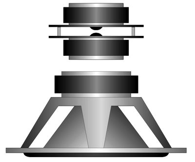
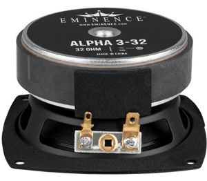
In post 451, I detailed the theory behind this arrangement. In short, the three drivers provide 360 degree radiation in the horizontal plane. If we place then atop a woofer that fires downward into the speaker enclosure, we get an approximation to an omnidirectional speaker. Or, we could use two 8-ohm woofers wired in parallel, with one tweeter and woofer firing from the back of the cabinet, while one tweeter and woofer fire on the front. In both examples, we got away with using low-valued crossover parts and presenting to the amplifier an 8-ohm load. While looking for 16-ohm drivers, I discovered that Eminence makes a 32-ohm 3-inch fullrange.
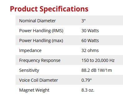
I was keen to find out how its SPL was specified. Here is the answer:
Just what I was hoping to see: 1W at 1M. So how much AC voltage is needed to produce one watt into a 32-ohm load? The following formula is handy. Power = Vrms²/Rspeaker When we solve for V, we get: Vrms = Sqrt(Rspeaker/Power) Since power equals 1, we reduce it to: Vrms = Sqrt(Rspeaker) The square-root of 32 is 5.656, which is twice the test voltage for 8-ohm drivers. This tells us that if we placed four of these 32-ohm drivers in parallel, the load impedance would be 8 ohms and the SPL with 2.828Vrms would equal to 88.2dB - 6dB + 12dB, or 94.2dB. The logic here is that four times the radiating surface area equals 20•log(4) or +12dB; but since the test voltage was twice the 8-ohm level, we must subtract 6dB. In other words, if the driver had been tested with the lazy 2.828Vrms for 8-ohm drivers, the SPL would have been specified as being 82.2dB, as we incur a 6dB drop in SPL when we halve the test AC voltage Why would anyone want an 8-ohm loudspeaker made up of four 32-ohm drivers? The answer is those who own or want to make a small OTL amplifier that holds two 300B output tubes per channel. A switch at the back of the speaker enclosure would allow selecting either 8 ohms or 128 ohms. I assume that a powered subwoofer would be used to fill in the missing bass. By the way, an OTL output coupling capacitor of 8.3µF would crossover at 150Hz. See post 195 for more details and how to add an 8-ohm tweeter. So little time, so many ideas.
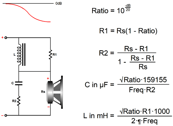
Shelving Network for Loudspeakers Let's say that you own a pair of fullrange drivers that either lack bass or highs. Assuming weak bass, here is a passive solution.
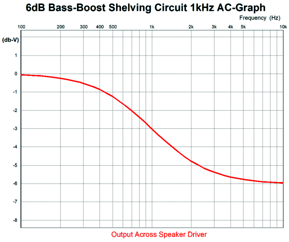
Resistor Rs is the speaker impedance. Since the circuit is passive, we can only boost the bass by cutting the highs. In other words, we must pay an insertion loss. The first step is to decide on how big a boost we need. +3dB? +6dB? Next, we must find the voltage ratio of the insertion loss. Once we have this ratio, we can go down the list of formulas. By the way, in the formulas we take only the square-root of the ratio, not the entire line. A boost of 6dB entered in the top formula yields a ratio of 0.5, whose square-root is 0.707. Here is a SPICE-generated graph of the circuit with a 6dB boost in the lows with a center frequency of 1kHz.
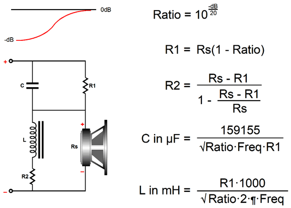
Of course, we could raise or lower the center frequency as needed. If we desire a high-boost, we use the following circuit and formulas.
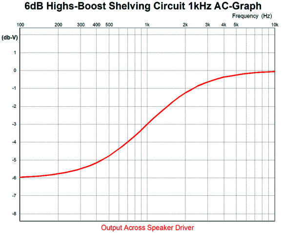
Once again, here is a SPICE-generated graph of the circuit with a 6dB boost in the highs.
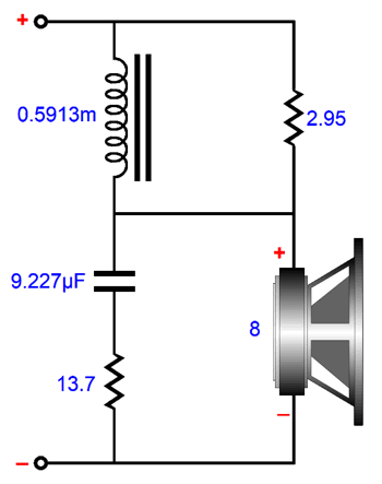
The center frequency was 1kHz. With both circuits, I would use high-power resistors. I like the Mills non-inductive wire-wound types, which are readily available in an 11W package. Okay, here is design example that delivers a +4dB boost to the bass.
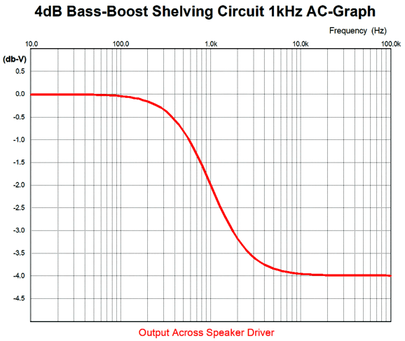
I ran the circuit in SPICE and here is the result.
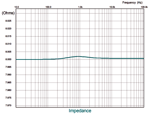
Just what we were aiming at: a 4dB boost to the lows with a center frequency of 1kHz. No doubt some are thinking that such a result might come at too high a price, as an extremely low input impedance at any frequency would prove undesirable. Well, judge for yourself.
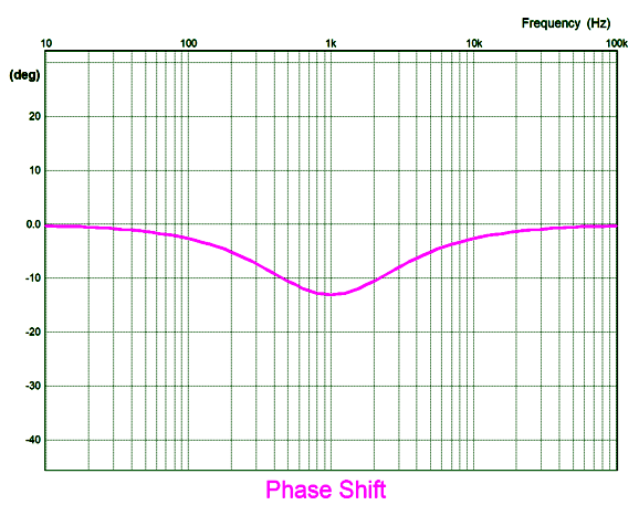
Note that the hump is only 2milliohms higher then 8-ohms. Sure that looks fine, but what about the speaker's phase response?
Actually, I was also worried about the phase characteristics of the circuit, but 13 degrees at 1kHz is not anything I would fret about. Moreover, I would move the center frequency far lower in actual use, say 300Hz, so at 3kHz, where our ears are most sensitive to phase aberrations, we would be doing even better. Okay, but what about using a current-output amplifier, not the typical voltage-output amplifier? A good question. I Ran the same SPICE simulations with a current source, rather than a voltage source. The results were the same. Same ruler-flat 8-ohm impedance, same -4dB insertion loss, and same 13 degree phase shift at 1kHz.
Music Recommendation: Dang Pleasant Music
All deliver a smooth and serene jazz that we used to call seduction-jazz forty years ago. In addition, all are nicely recorded, particularly the last album. Moreover, all are available at Tidal. //JRB
User Guides for GlassWare Software Since I am still getting e-mail asking how to buy these GlassWare software programs:
For those of you who still have old computers running Windows XP (32-bit) or any other Windows 32-bit OS, I have setup the download availability of my old old standards: Tube CAD, SE Amp CAD, and Audio Gadgets. The downloads are at the GlassWare-Yahoo store and the price is only $9.95 for each program. http://glass-ware.stores.yahoo.net/adsoffromgla.html So many have asked that I had to do it. WARNING: THESE THREE PROGRAMS WILL NOT RUN UNDER VISTA 64-Bit or WINDOWS 7 & 8 or any other 64-bit OS. One day, I do plan on remaking all of these programs into 64-bit versions, but it will be a huge ordeal, as programming requires vast chunks of noise-free time, something very rare with children running about. Ideally, I would love to come out with versions that run on iPads and Android-OS tablets.
|
Special Thanks to the Special 86!
I am truly stunned and appreciative of their support. In addition I want to thank the following patrons:
All of your support makes a big difference. I would love to arrive at the point where creating my posts was my top priority of the day, not something that I have to steal time from other obligations to do. The more support I get, the higher up these posts move up in deserving attention. Only those who have produced a technical white paper or written an article on electronics know just how much time and effort is required to produce one of my posts, as novel circuits must be created, SPICE simulations must be run, schematics must be drawn, and thousands of words must be written. If you have been reading my posts, you know that my lifetime goal is reaching post 1,000. I have 532 more to go. My second goal is to gather 1,000 patrons. I have 914 patrons to go.
The Tube CAD Journal's first companion program, TCJ Filter Design lets you design a filter or crossover (passive, OpAmp or tube) without having to check out thick textbooks from the library and without having to breakout the scientific calculator. This program's goal is to provide a quick and easy display not only of the frequency response, but also of the resistor and capacitor values for a passive and active filters and crossovers. TCJ Filter Design is easy to use, but not lightweight, holding over 60 different filter topologies and up to four filter alignments: While the program's main concern is active filters, solid-state and tube, it also does passive filters. In fact, it can be used to calculate passive crossovers for use with speakers by entering 8 ohms as the terminating resistance. Click on the image below to see the full screen capture.
Tube crossovers are a major part of this program; both buffered and un-buffered tube based filters along with mono-polar and bipolar power supply topologies are covered. Available on a CD-ROM and a downloadable version (4 Megabytes). |
||

 jazz, JAZZ, jazz by Michael Wolff Trio
  Third Round by Manu Katché
  Fascinoma by Jon Hassell & Ry Cooder
 Nuit d'ombrelle


| www.tubecad.com Copyright © 1999-2019 GlassWare All Rights Reserved |