| John Broskie's Guide to Tube Circuit Analysis & Design |
20 October 2019 Post 480
Simple Class-A Hybrid Amplifier I wondered, however, if I really needed to go full class-A, as maybe a rich class-AB was sufficient. I traveled to the hardware store and bought a long shielded power extension cord with a house-ground pin, which was rare back then (in fact, none of my wall-voltage sockets held proper house-ground sockets, just two thin slits). I then wired up the plug end of the cord inside my amplifier, attaching it to the bias circuit. At the female end, inside a small Bud box, I attached a potentiometer and some resistors. I then sat down and listened away to mono LPs, while adjusting the idle current from afar. The higher the idle current the better the sound—seemingly a straight line all the way up to smoke and burnt output transistors. Literally. I had burned out the output stage. (I would be embarrassed to admit how often I had done that before. We must often make sacrifices when pursuing knowledge.)
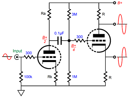
Here is what troubled me: as I moved the idle current beyond the needed idle current for class-A push-pull operation, the sound kept improving. Why did this trouble me? As a teenager, I read many books on sports cars design, engine design, including several books by the wonderful Colin Campbell. The result was that I knew that optimal tire widths existed for a given car and that exceeding the width reduced performance. The same held true for all the other aspects of racing and sports car design—something that my motor-head buddies could not grasp: the concept of optimal values, that more wasn't always better. But my experiment with class-A seemed to establish a straight line upwards, with more always being better. Well, the following hybrid design might provide the answer. We start with the tube half of the circuit. A grounded-cathode amplifier cascades into a split-load phase splitter.
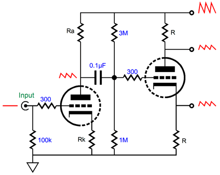
The design goal was for the input stage to split the B+ voltage and the power-supply noise at its output. Why? The split-load phase splitter will then subtract half of the power-supply noise from the power-supply noise itself and both of the phase splitter's output will contain equal amounts of in-phase power-supply noise, which the output stage will then ignore.
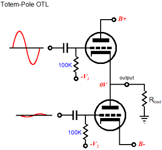
Here is another reason why class-A can sound so good. Let's use a conventional class-AB tube power amplifier as an example. If fed an equal amount of power-supply noise at each output tube's grid, the differential ignoring of common-mode signals, which is what the power-supply noise will prove to be, creates a power-supply-noise null at the secondary and the loudspeaker. Once the output stage moves out of its small class-A window of operation, the differential null ends and the power-supply noise become signal to be amplified. I label this occurrence as dynamically-induced poor PSRR (DIPP ?). In a class-A push-pull output stage, by definition and design, the output devices never cease to conduct, so the differential null continues. The two outputs from the split-load phase splitter could be used to drive to output tubes or two N-channel MOSFETs in a circlotron arrangement, but not two output tubes or two N-channel MOSFET in a totem-pole arrangement, as the top output device needs to see a vastly bigger input signal than the bottom output device.
Fortunately, Julius Futterman's OTL designs showed us how to make a split-load phase splitter deliver the needed asymmetrical output signals.
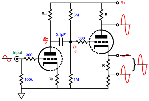
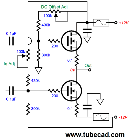
We add a resistor below the phase splitter's cathode resistor and feed the output stage's output signal to the nexus between the two resistors. The result is that the bottom and top output MOSFETs see the same source-to-gate input signal, in spite of the top MOSFET's source swinging up and down with the output signal.
Note how the bottom MOSFET's input signal is out of phase with the top MOSFET's input signal. As things stand, the output stage's output impedance is extremely high, not low, as both MOSFET function as common-source amplifiers, not source followers. In other words, the entire amplifier requires a negative feedback loop that returns the output signal to the input stage's inverting input, which in this example is the input triode's cathode.
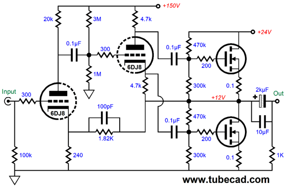
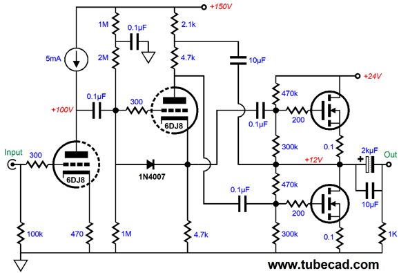
I purposely left out the part values, as I want to avoid mental overload. Note how the MOSFET-based output stage runs off a 24Vdc power-supply rail and how the tubes see a 150Vdc B+ voltage. Also note that the output signal is DC coupled to the negative feedback loop resistor. Lastly, note how the DC bias voltage for the split-load phase splitter is one fourth the B+ voltage. Okay, now let's look at the part values.
The 6DJ8 works well with the relatively low B+ voltage and provides a gain (15 or so) in this circuit roughly equal to half its amplification factor, 31 roughly. The MOSFET are not labeled. I used IRPF250s in my SPICE simulations, but any big robust N-channel power MOSFET could be used. The IRFP250 is, in fact, long in the tooth. If you would prefer to run the output MOSFETs in source-follower mode, we need only flip the outputs from the phase splitter.
It looks entirely negative feedback free, but the split-load phase splitter and the output MOSFET define a negative feedback loop of sorts. Don't see it? Imagine forcing a positive voltage pulse on the output. The pulse would force the top MOSFET's gate to be effectively more negative relative to its source, which would prompt less current flow from the top MOSFET. At the same time, the pulse would travel through the phase splitter's triode and appear at its plate, which would make the bottom MOSFET's gate more positive relative to its source, provoking greater current conduction, which would buck the pulse at the output, as would the top MOSFET reduced current flow. Negative feedback in other words and an intrinsically low output impedance. Our—as yet unstated—goal is a peak output voltage swing of 8V, which translates into 4W into an 8-ohm load. The 6DJ8's gain exceeds this peak voltage, so we could add a negative feedback loop, so the gain would fall to 8, which means 1Vpk of input signal will produce full output.
This is the classic inverting amplifier negative feedback arrangement, so the input impedance will roughly equal the 10k input value. Note that the input stage's cathode resistor is bypassed, as we want to increase this stage's gain. If we desire even more gain, say we want to build an integrated amplifier that offers line-stage amplifier gain, then we could replace the input stage's plate resistor with a constant-current source.
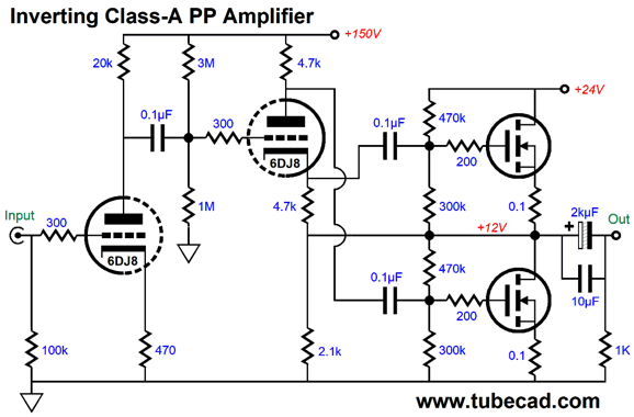
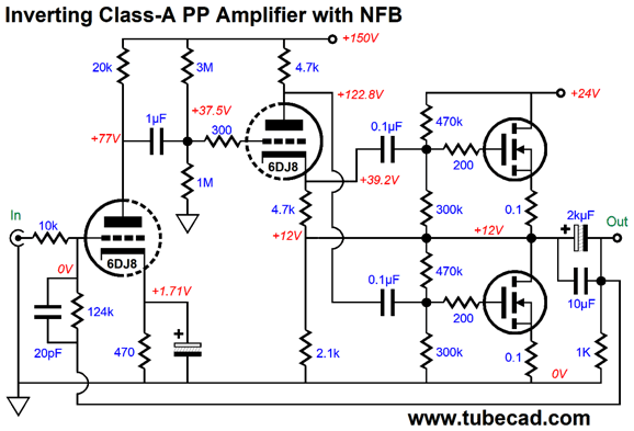
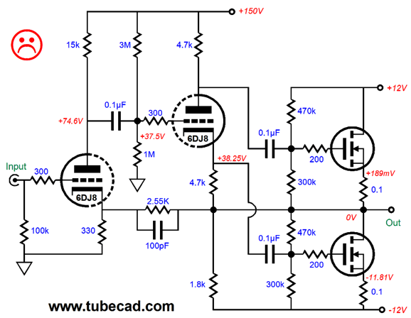
Note that the output is inverted, which can be fixed by simply flipping the loudspeaker connections. Also note that no negative feedback loop, other than the split-load phase splitter's arrangement with the output stage, is used, so the amplifier gain will equal the input triode's amplification factor, about 31 with the 6DJ8. Since the input stage, the grounded-cathode amplifier loaded by the constant-current source, leaks no power-supply noise at its output, we must shield the split-load phase splitter from the B+ ripple. We do so by using the 10µF capacitor that terminates into the output. The diode was added to protect the phase splitter's triode at start-up. Okay, what's not to like? I know many are troubled by the output coupling capacitor, preferring to see DC coupling. We can use a bipolar power supply, but it holds a pitfall we must avoid.
Do you see what earned the unhappy face? The negative power-supply rail contains ripple that the bottom MOSFET won't find in its input signal from the phase splitter. Not good, as the ripple will be treated as signal to be amplified. The workaround is to switch the outputs from the phase splitter, so the output MOSFETs operate in source-follower mode; and to place another resistor in series with the split-load phase splitter's plate resistor and add a capacitor to couple the negative power-supply rail noise to the signal.
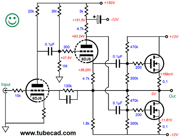
The impedance at the split-load phase splitter's plate is extra high, so almost all of the -12V power-supply rail noise will superimpose upon the bottom MOSFET's gate signal. Another workaround is to use a differential input stage instead.
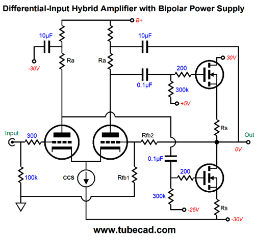
This circuit appeared recently in post 471. By the way, when running a bipolar power supply, fusing becomes critical, as we don't have an output coupling capacitor to save the loudspeaker.
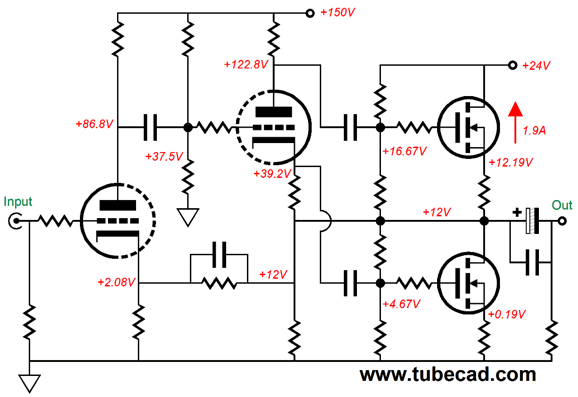
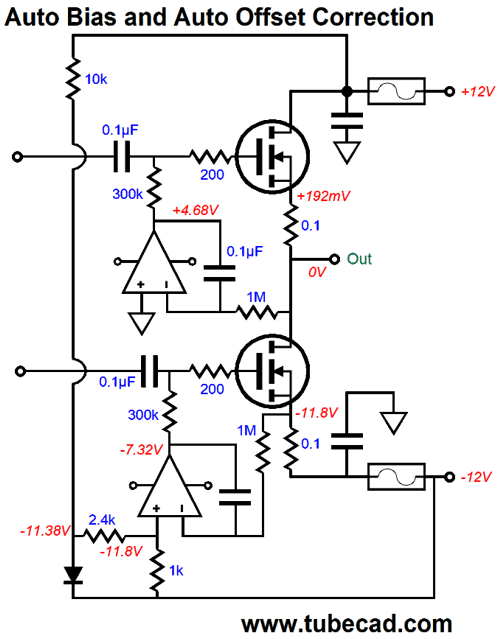
At no time do we want the output voltage to stick to either the positive or negative power-supply rail voltages. Imagine that the positive fuse blows. What happens? Both the top and bottom output MOSFETs cease to conduct and the loudspeaker is safe. If the negative fuse blows, the bottom MOSFET turns off, while the top MOSFET still conducts, but not much. True, the top MOSFET had been drawing 1.9A at idle, but with an effective source resistor of 8.1 ohms, its current draw plummets to a safe value. Okay, we can get fancier still. The +/-12Vdc power-supply rail voltages are perfect for OpAmp use, so why not use them? Once again, one great advantage of running class-A is that we can easily implement auto-bias.
The top OpAmp centers the output stage so no DC offset occurs. The bottom OpAmp sets the idle current. It does so by monitoring the voltage drop across the bottom MOSFET's source resistor and comparing it to a reference voltage derived from the voltage drop across the diode (1N4007). The critical OpAmp specification is the ability of the inputs to extend down to (or below) the OpAmp's negative power supply voltage. Not all OpAmps can. In fact, many OpAmps lose their minds in the presence of an excessively negative input voltage, which can cause a phase flip at the output or a torrent of current flowing from the input pin. Not good. The LT1013 can accept input voltages down to its negative power supply voltage. Moreover, the LT1013 was designed to prevent unwanted phase flipping. As always, do carefully read the OpAmp's data sheet. Note that both OpAmps should be powered from the un-fused side of the bipolar power supply. If the positive rail's fuse blows the reference voltage created by the diode will collapse, as will the bottom MOSFET's current conduction. If the negative rail's fuse blows, the top OpAmp will shut down the top MOSFET's conduction. Remember where I started this discussion, on the concept of optimal values, that more wasn't always better? Well, getting 4W into an 8-ohm load only requires a peak voltage swing of 8 volts and a peak current swing of 1 ampere, so why do all the design examples show an idle current flow of 1.9A, when only 500mA is needed for class-A push-pull operation? Here is why.
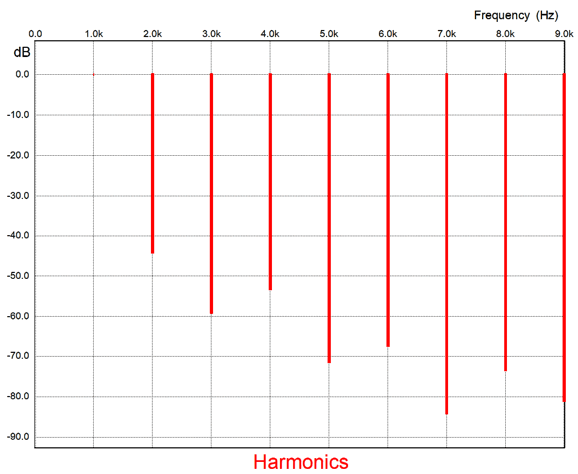
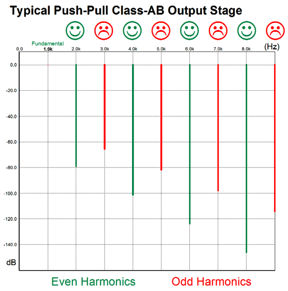
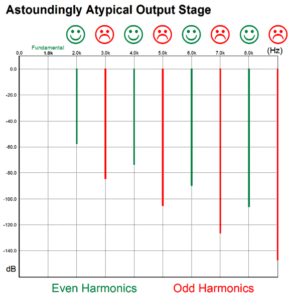
This Fourier graph shows the harmonic structure at full output, i.e. 4W at 1Khz into 8 ohms; all the design examples exhibit the same Fourier breakdown of harmonics. A glorious sight to behold, as the odd harmonics are all suppressed more so than the even harmonics—just the opposite of every class-AB amplifier in existence, which always further attenuate the even-order harmonics.
The ear likes even-order, but dislikes odd order harmonics. Add some 5th, 7th, and 9th order harmonics to an otherwise pure tone and watch your skin crawl. Audiophiles endlessly pursue a more pleasing sound; mostly, in vain. Single-ended amplifiers get us closer, but still fall short. I believe what we long for is that rare harmonic structure.
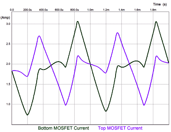
The price we paid in these design examples was vastly reduced power output. With the same VA sized power transformer but high secondary voltages and the same massive heatsink and two MOSFET output devices, we could have built a 100W class-AB amplifier—but at the cost of losing that rare harmonic structure. The graph showing the MOSFET current conduction through two cycles is weird.
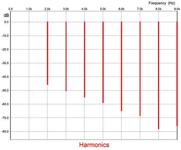
It seems that the MOSFETs do not know that they are producing sinewaves. Here is the graph for the same power output, but with an idle current of 500mA.
Still lovely, but not astoundingly atypical.
Inductor-Loaded Push-Pull Class-A
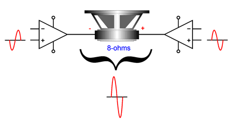
Amazingly enough the amplifier put out 32W. Why is that amazing? Think about this: if we used a bridged amplifier, wherein two amplifiers ran off the 12V battery, we could at the very most a 12Vpk voltage swing, which translates into just 9W, not 32W. Even if we shorted the 12V battery with the 8-ohm speaker and let the 1.5A DC current flow, we would only get 18W. So how did Richard Burfoot get 32W?
His solution was to set up bridged inductor-loaded MOSFETs, so a peak voltage of 24V would be possible and 36W could be realized. Due to losses, he got 32W. Bravo. In fact, he achieved an efficiency of 45%, which comes close to the theoretical maximum of 50%.
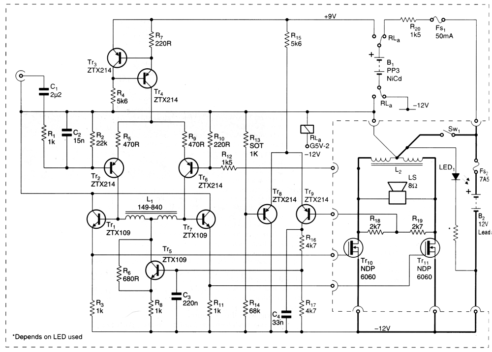
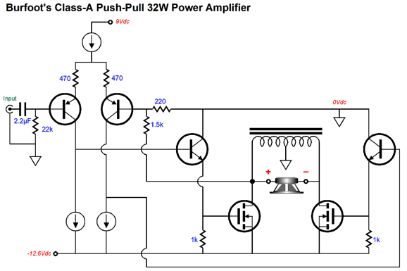
It's not nearly as complicated as it may appear. Trust me. His goal was to sidestep hum. Even if an amplifier's output is hum free, its huge power transformer will buzz away. Battery power, in contrast, is quiet and sidesteps house-ground issues. In addition to the 12V car battery, Burfoot used a 9V battery to create a positive power-supply rail. (The original schematic holds a typo, as the negative feedback loop is not terminated at the positive output terminal.) Here is a simplified version of the circuit. (A car battery actually puts out 12.6Vdc.)
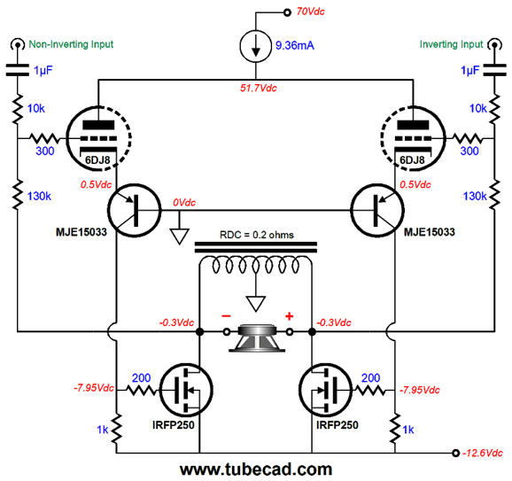
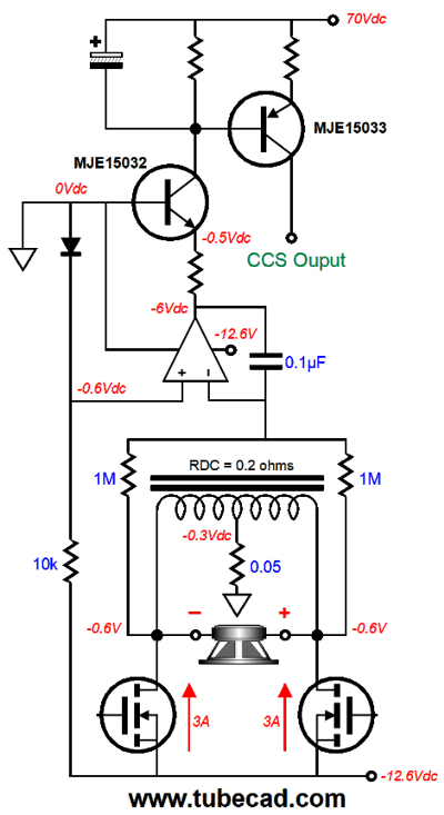
An inductor is much like a magical constant-current source that displaces no voltage dissipates no heat. Well, ideally that is what would happen, but all real inductors present some DCR and, thus, dissipate some heat. In fact, Mr. Burfoot uses the center-tap choke's DCR to drive his auto-bias circuit. Transistors Tr8 and Tr9 form a differential amplifier configured as a DC servo. If the MOSFETs draw too much current, the voltage drop across the center-tapped inductor's DCR will increase and the servo will lessen the MOSFETs' gate voltages. He didn't use an actual center-tapped inductor; instead, he used half of an existing power transformer, the center-tapped secondary, which was a risky move, as not all iron is equal. I have performed many tests on power transformers and chokes, finding widely different bandwidths. In general, most power-supply transformers and chokes make very poor audio inductive devices. In other words, a high-quality audio-grade, wide bandwidth inductor requires the care and special core as an audio output transformer. His input stage also requires a center-tapped inductor, but this time he used half of an audio transformer. (When I worked at Beige Bag Software, I got a few emails that showed fabulous results from center-tapped inductors as loads. I then poisoned the well by reducing the inductive coupling from 100% to 98% and placing two 1-ohm resistor in series with the center-tapped inductor, one at each end. Most of the magic fell away.) This brings up an interesting question: What if he had used an output transformer instead? One advantage is that it would prove vastly safer, should a MOSFET melt down. In addition, potentially far more output wattage could be realized. For example, if he doubled up on the output MOSFETs, while still running 3A per MOSFET, and used a step-up, not a step-down, output transformer, the amplifier would put out up to 72W. (Reality would deliver something closer to 64W. Still, this is an impressive amount of class-A watts.) Okay, what if we make a hybrid version instead? We could use triodes in retrograde cascode with PNP transistors to drive the MOSFET gates directly.
The constant-current source both shields the triodes from power-supply noise and helps ensure balance and sets the OPS idle current. I like that each output terminal gets its own feedback loop, rather than relying on the center-tapped inductor's mutual inductance. This amplifier requires a balanced input signal and it uses the inductor's DCR to monitor the idle current flow. We could get fancier by using an OpAmp-based DC servo to control the constant-current source's idle current.
The PNP MJE15033 is the constant-current source. The DC servo strives to maintain an identical DC voltage at both its input pins. If the output stage draws too little idle current, the servo will increase the constant-current source's current draw; if it draws too much, it will lessen it.
Music Recommendation: Mujeres del Tango
Give the album a listen and see if you do not, like me, long to read the lyrics in English. Here is an example:
//JRB
User Guides for GlassWare Software Since I am still getting e-mail asking how to buy these GlassWare software programs:
For those of you who still have old computers running Windows XP (32-bit) or any other Windows 32-bit OS, I have setup the download availability of my old old standards: Tube CAD, SE Amp CAD, and Audio Gadgets. The downloads are at the GlassWare-Yahoo store and the price is only $9.95 for each program. http://glass-ware.stores.yahoo.net/adsoffromgla.html So many have asked that I had to do it. WARNING: THESE THREE PROGRAMS WILL NOT RUN UNDER VISTA 64-Bit or WINDOWS 7 & 8 or any other 64-bit OS. One day, I do plan on remaking all of these programs into 64-bit versions, but it will be a huge ordeal, as programming requires vast chunks of noise-free time, something very rare with children running about. Ideally, I would love to come out with versions that run on iPads and Android-OS tablets.
|
Special Thanks to the Special 85!
I am truly stunned and appreciative of their support. In addition I want to thank the following patrons:
All of your support makes a big difference. I would love to arrive at the point where creating my posts was my top priority of the day, not something that I have to steal time from other obligations to do. The more support I get, the higher up these posts move up in deserving attention. Only those who have produced a technical white paper or written an article on electronics know just how much time and effort is required to produce one of my posts, as novel circuits must be created, SPICE simulations must be run, schematics must be drawn, and thousands of words must be written. If you have been reading my posts, you know that my lifetime goal is reaching post 1,000. I have 523 more to go. My second goal is to gather 1,000 patrons. I have 915 patrons to go.
The Tube CAD Journal's first companion program, TCJ Filter Design lets you design a filter or crossover (passive, OpAmp or tube) without having to check out thick textbooks from the library and without having to breakout the scientific calculator. This program's goal is to provide a quick and easy display not only of the frequency response, but also of the resistor and capacitor values for a passive and active filters and crossovers. TCJ Filter Design is easy to use, but not lightweight, holding over 60 different filter topologies and up to four filter alignments: While the program's main concern is active filters, solid-state and tube, it also does passive filters. In fact, it can be used to calculate passive crossovers for use with speakers by entering 8 ohms as the terminating resistance. Click on the image below to see the full screen capture.
Tube crossovers are a major part of this program; both buffered and un-buffered tube based filters along with mono-polar and bipolar power supply topologies are covered. Available on a CD-ROM and a downloadable version (4 Megabytes). |
||


| www.tubecad.com Copyright © 1999-2019 GlassWare All Rights Reserved |