| John Broskie's Guide to Tube Circuit Analysis & Design |
22 November 2019 Post 483
My Latest Audio Project
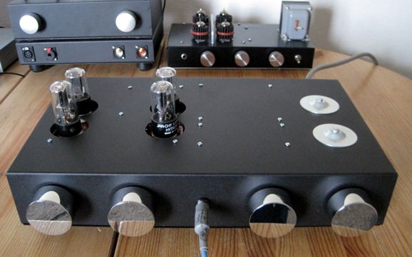
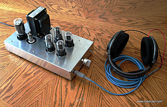
I got all my wishes and the result is the best sounding tube-based headphone amplifier my Sennheiser have encountered. Actually, I will go farther than that and say that is the best headphone amplifier they have encountered, either solid-state or tube-based. It's dead quiet and I can hear new subtle sounds on albums I have heard countless times. Indeed, the dynamic Sennheisers sound almost like electrostatic headphones at times.
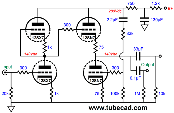
In my last PCB production run, I had included a new octal Aikido stereo PCB, which brought the PCB into a new revision. It's slightly longer and the spacing between tubes is greater. More importantly, I restored the Aikido push-pull option. Because I had made so many changes, I had to build up a test board, which explains how this project started. The circuit is easy enough.
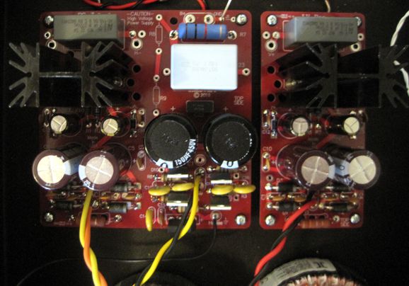
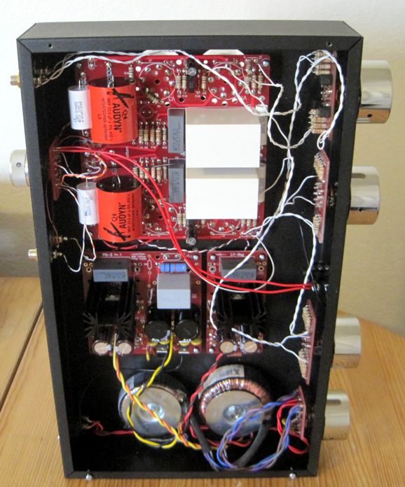
Resistor R16 is a current-sense resistor that creates the needed anti-phase drive signal for the bottom output triode, so true push-pull operation can obtain. At the same time, the Aikido cathode follower output stage actively rejects power-supply noise. The two output coupling capacitors, 33µF and 0.1µF, are in parallel when driving headphones, but only the 0.1µF capacitor attaches to the output RCA jacks. The power supply is one of the new PS-3, with 150µF/450V reservoir capacitors; in addition, an LV-Reg power supply is used to power one channel's heater elements, while the low-voltage regulator on the PS-3 powers the other channel's heater elements. Two toroid power transformers were used.
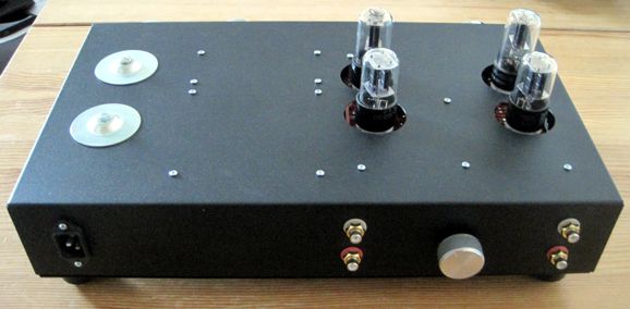
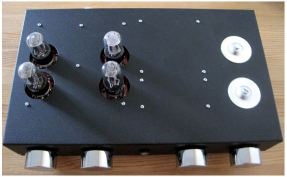
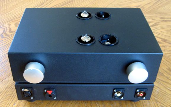
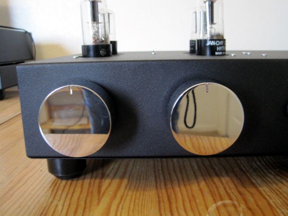
The chassis is a steel "Bud Box" from Hammond, which is 10 by 17 by 3 inches and black painted at the factory. The only vent holes are those four that allow the tubes to protrude from the chassis. Convection air currents within the enclosure work to the cool the electronics.
This was one of the few projects I have built that didn't feel cramped, as I usually pack far too much into far too small a space. Not this time. Originally, I planned on putting the two power transformers in a separate metal box atop the enclosure, but as I laid out the design, I saw that everything could fit inside one box. The heater transformer is rated for 50VA, while the B+ voltage transformer is rated for 25VA. One thought I entertained was using two 25VA heater transformers, one stacked atop the other. Why? By flipping the wall voltage phase to one of the transformers, we can produce a hum radiation null, as the two transformers' AC fields will be in anti-phase and largely cancel. So why didn't go this route? I owned the 50VA transformer, but not two 25VA 12Vac transformers. Nonetheless, this trick is worth remembering, especially when building a phono stage.
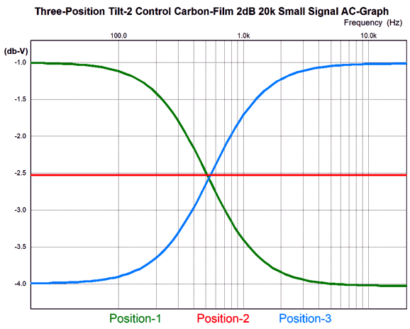
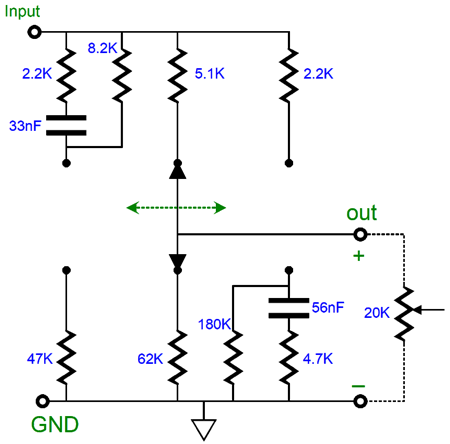
The Tilt-2 Control centers at 600Hz and uses only carbon-film resistor in my build. Alas, the 2dB tilt is too subtle. I should have set it to a 3dB or 4dB frequency response tilt. Here is how I plan on changing the Tilt-2 slopes.
Here are the needed part values.
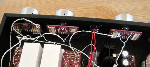
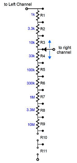
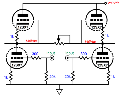
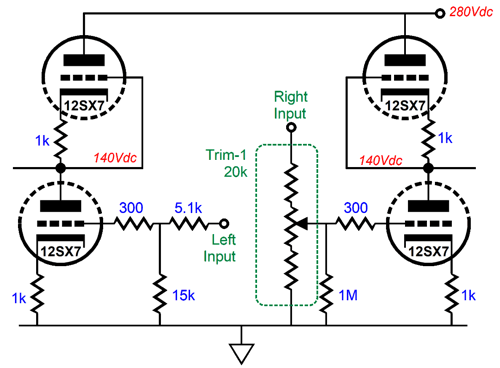
The balance control is simply one of my Trim-1 11-position stepped attenuators, which feeds only the right channel. The left channel get a two-resistor voltage divider set to -2.5dB of attenuation. In other words, when the balance knob is centered (i.e. on its sixth position), both channels see a -2.5dB of attenuation. As the knob is rotated to the left, the left channel become effectively plays louder, as the right channel is increasingly attenuated; when it turns to the right, the right channel gets louder. I now realize that the 0.5dB steps are to fine and that I should have used 1dB steps. The stereo-mono blend control is interesting. Another Trim-1 stepped attenuator is used, but in an odd fashion. It's input and output attach to the two input stages. As the knob is rotated to the right, the two channels blend together; at the last step, they completely bridge together, creating a mono audio signal. At the first position, pure stereo, with no blending occurs. Why have such a knob? Headphone listening is not like loudspeaker listening. With headphones, each ear gets the ultimate stereo separation; with loudspeakers, a blend of both channels. In other words, I have found that a little blend goes a long way to making headphone listening sound more natural.
Note the exponential resistor values. I was surprised to find that placing the control in its center position (i.e. on its sixth or seventh position) resulted in the optimal blend for most recordings.
The Trim-1 is placed between the input stages. At one extreme, stereo; at the other, mono. The second Trim-1 is used at the left channel's input.
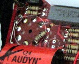
This 11-position stepped attenuator is parked at its sixth position. The decrements are in0.5dB, so the ouput at the middle position is -2.5dB. This same amount of attenuation is achieved by the 5.1k and 15k resistors at the right channel's input. When I first listened to the completed headphone amplifier, the bass was overwhelming, yet it measured flat. I had encountered this anomaly before with Teflon-coated wire, so I let the amplifier run for half a day without listening to it. My second listening heard something far closer to flat bass, but still fatter than I expected, so I waited another day of burn-in before listening. The bass had been tamed. Why did the bass seemed boosted before? I have no substantive idea. The crazy thing is that it measured flat, but sounded bass boosted. Perhaps, some odd phase shift occurs that tricks the ear into hearing bass that isn't there. I am not alone, however, in hearing this temporary bass boost, as my friend Glenn heard it before with Teflon interconnects and I thought he must have been crazy, as wire is just wire. And as wire is passive, the only way the bass could be boosted was if the highs were depressed. Then I experienced the same initial bass boost with Teflon-coated loudspeaker cables and I didn't want to conclude that we were both crazy, although we certainly might be.* Do not forget that hearing is not as simple or as passive as you might imagine. Now we come to the mixed emotions I hold for my latest tube-based headphone amplifier. I made a few screw ups in building the headphone amplifier. For example, I got confused where the tube holes were going to be and I drilled big holes for my hole punch where the toroid power transformers were meant to go. I fixed that problem by using an extra set of toroid washers on the top of the enclosure. I made the tube holes too big, so I could not use my plastic hole trims. And, finally and most importantly, the PCB holds a screw up, which I accidentally made when I moved the output tube position further back during the PCB layout. Only the left channel holds the mistake, which I overcame by soldering one resistor lead to the tube socket directly.
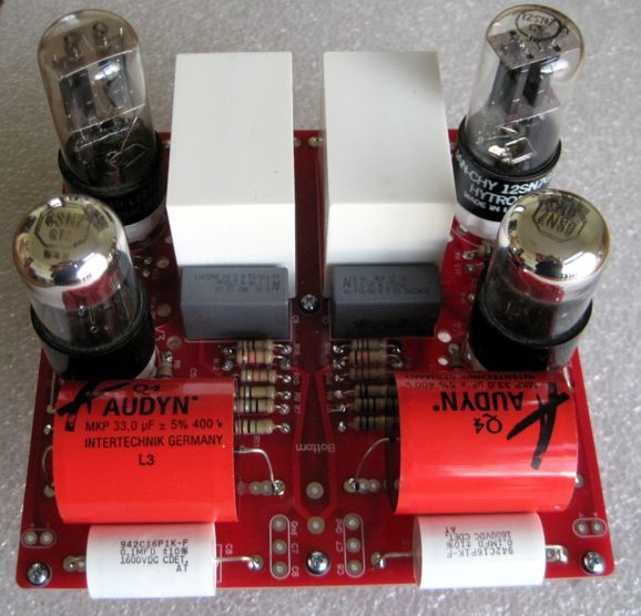
See how resistor R6 attaches to pin 5 on the tube socket. Due to this error in layout, I am inclined not to release this PCB. I thought about painting over the faulty solder pad and printing correction instructions, but it's still a hassle and a worry. Perhaps, the best route to follow is to wait for the next PCB production run (next year). At the same time, I know many born hackers, like myself, who would laugh at such a simple fix. In short, I have to think some more.
(The tube sockets actually are mounted onthe topside of the PCB, but I needed a photo of the new PCB.) Something else worthy of extra thought is why does this Aikido PP headphone amplifier sound better than my previous Aikido PP headphone amplifier? In theory, it shouldn't as the ECC99 output tubes offer far more transconductance than the 12SN7s. In addition, the previous Aikido PP headphone amplifier uses a regulated B+ voltage.
As I see it, there are only two possibilities. The first is that old NOS tubes are just wonderful, so they easily stomp on new tubes. Sadly, no one makes current-production 12SX7 and 12SN7 tubes, so I cannot hold a shootout between old and new tubes. But here is the paradox: these exact same tubes are used in one of my older tube-based headphones amplifier, with exactly the same audio circuitry, but the older amplifier does not sound as good. But then, it uses a single regulated heater power supply for both channel, whereas the new PCB requires one power supply per channel.
See post 181. The other possibility is that the big 130µF/500V polypropylene metallized film capacitors in the each channel's RC filter are working better than the capacitors used in the noval-based headphone amplifier or the amplifier shown above that uses a Janus regulator with a 5R4 tube rectifier. I lie. I just thought of third and fourth possibilities. With the previous amplifier, the HD650 are driven in balanced mode, whereas the new amplifier uses the typical unbalanced fashion with 1/4" jack. Does that matter? It can for the reason that the unbalanced output uses the fancy Cardas cable, whereas the balanced output connects through the cable that came with the headphones. Normally, I would not think twice about the cable, but now I must, having heard the new Danacable $3,500 Lazuli Nirvana headphone cables at the 2019 RMAF. See post 478 for more on the cables. Unlike my previous Aikido PP amplifiers, I ran the input stage very lightly, in terms of current flow. Why? I am running a hotter B+ voltage, 280Vdc versus 240Vdc, so I wanted to limit the first stage's dissipation. I have noted that light current sometimes results a a punch, dynamic sound, but often highs-limited. In contrast, high-current displays an extended high frequency response, but sounds less dynamic. (These observation have mostly cum form solid-state circuits, where I might have been running into beta-droop.) In the Aikido topology, the input stage doesn't really drive any load, as it is followed by an ultra-high input impedance from the Aikido cathode follower.
MC Pre-Preamps Part 2
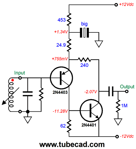
Now, let's invert the topology, so a PNP transistor is used as the input device and the compound transistor is an NPN type.
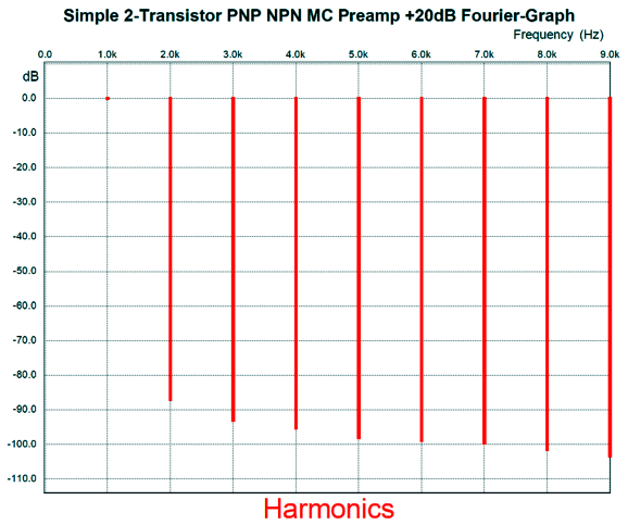
As we would expect, the performance is nearly identical to the original version. Here is the Fourier graph for 10mV of output signal at 1kHz. Note the single-end cascade of harmonics. THD is below 0.001%. (At least it is in SPICE simulation.)
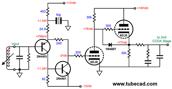
What is different, however, is that the output coupling capacitor now blocks a negative DC offset voltage, not a positive voltage. Does this matter? It does if we remove the coupling capacitor from the circuit. Why would we eliminate the output coupling capacitor? Here is the idea: we allow the negative DC to be exposed and use this negative voltage to bias the input triode in a 40dB tube-based phono stage, such as the Tetra.
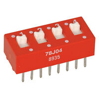
The 6DJ8 triode no longer needs a cathode resistor and its bypass capacitor, so its cathode is grounded directly. The grounded-cathode amplifier input stage is followed by a cathode follower, which is followed by a passive RIAA equalization network, which in turn is followed by a second CCDA stage made up of a grounded-cathode amplifier and cathode follower. Only two coupling capacitors will be used: one after the passive RIAA equalization network and one at the output. The B+ voltage is a purposely low 150Vdc, as heater elements would be powered by the +12Vdc power-supply rail. In other words, we do not want the cathode follower's heater element to be at to great voltage differential with the cathode voltage. For most audio tubes, the maximum heater-to-cathode voltage is 100V. On the other hand, if gave the heater elements their own separate and referenced to a higher DC voltage, then we could up the B+ voltage to a limit of about 300Vdc. Nonetheless, the 6DJ8-based input stage will develop a gain close to 30dB, which combined with the gain from a 12AT7-based second CCDA stage and minus the 20dB insertion loss from the passive RIAA equalization network would yield an easy 40dB from the tube portion of the phono stage. Speaking of gain, I upped the pre-preamp's gain t 20dB (10X), as I believe that amount is more in line with common use. The solid-state portion of the circuit is so simple that it could easily be assembled on perf board, although a PCB would be welcomed. A welcomed addition might be bias potentiometer for the solid-state pre-preamp, so that its output DC voltage could be adjusted. The only problem with idea is that I never want DC current to flow through a potentiometer's scrapper. Perhaps, we could use one of those multiple switches arrayed in an IC format, in other words a DIP switch.
We would increase the 453-ohm resistor to a 470-ohm and then use the switches to place shunting resistances across it, so we could set the needed DC offset output voltage for the proceeding triode stage.
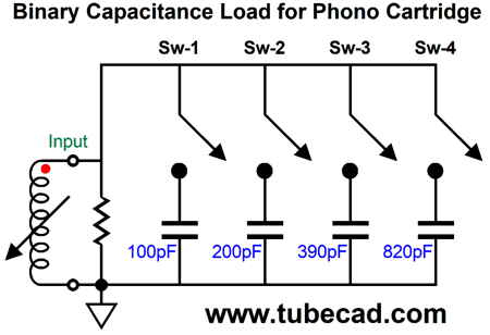
Binary Capacitance for Phono Cartridges
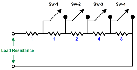
A 16-position binary encoder switch will yield the following results.
An X denote that the switch is closed What if you don't need anything close to 1500pF? The solution is to use a different set of capacitors, say 30pF, 62pF, 120pF, and 240pF, which yields a maximum of 344pF, in fifteen 30pF increments.
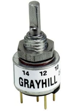
Since the switch contacts will only see an AC signal in millivolts, it is essential that the contacts are hard gold. Although silver a better conductor than gold, it makes a poor switch contact when dealing with small audio signals. On the other hand, silver makes a better contact material when you are switching higher-voltage, high-current loads—something audio stepped attenuators never do, by the way! The line-level audio signal cannot burn off silver oxide tarnish. Many ignore this advice and use silver-contact switches anyway and get great results—for a while, then poor result, and, finally, no sound. The silver switch workaround is to employ a knife edged switching scrapper that shaves a thin layer of contact material off with each pass. (A switch with knife contacts requires periodic vacuuming, as the shavings can short out portions of the switch or circuit. In other words, these switches are open structures, not sealed.) One quick way to tell if a switch or really is suitable for audio signals is its maximum current rating. If it's only 30mA, then it is good to go; if it's over 500mA, begin to worry. I should point out that we can use binary switching with resistors, but with the resistors in series, not in parallel. For example, say we want a selectable -resistance, dummy-load resistor box that can handle 100W and offers 1 ohm to 16 ohms in 1-ohm steps. All we need is five 100W power resistors and four relay switches.
Note that the binary code runs in the inversion of the previous example. What this means is that if we use a 16-posistion binary encoder rotary switch to activate the four relays, the resistance will start at 16 ohms and step down to 1 ohm. The reason the maximum wattage varies is that each resistor experiences a different dissipation depending on its ratio of voltage it sees for each increment in resistance. For example, with an output impedance of 16 ohms, the 8-ohm resistor will dissipate half the power, so its 100W rating will double to 200W for the entire string. The 8-ohm resistor becomes the weakest link, as it sees the most voltage drop. Do not make the mistake of believing that five 100W resistor in series equals 500W of maximum dissipation; this would only hold true if each resistor presented the same ohmage. In this case, we would need 16 100-ohm resistors and a 16-posistion power rotary switch, which probably does not exist.
Back to MC Pre-Preamps
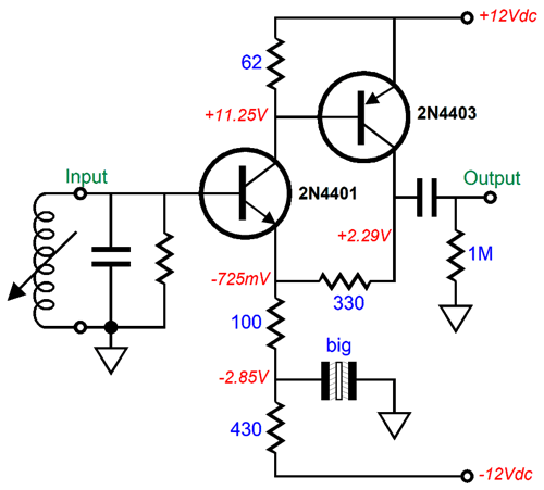
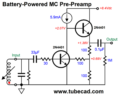
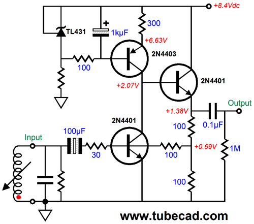
The input resistance looks as if it will be a low 30 ohms, but is in fact closer to 300 ohms. In other words, we still use shunt resistors to establish the desired load impedance for the moving-coil cartridge, usually between 50 to 200 ohms. The gain is 20dB, which can be raised or lowered by varying the resistor values. The input coupling capacitor should at least 33µF. The capacitor type show in the schematic is a non-polarized electrolytic type. If you have the room, you could use a polypropylene capacitor instead. The schematic glibly shows a 5.9mA constant-current source. This constant-current source could be made from an IC or the following discrete design.
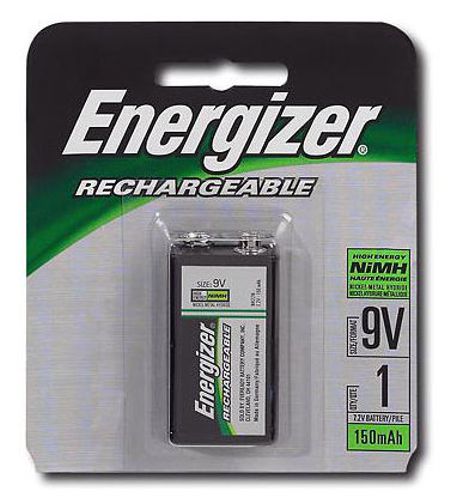
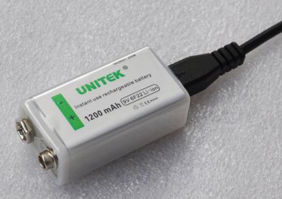
The adjustable Zener is either an LM431 or TL431 shunt 2.5V voltage reference. Since the expected load impedance is 47k, the output coupling capacitor can be as little as 0.1µF. The circuit inverts the output phase, so the cartridge wires should be flipped. I would set the 9V batteries, one per channel, to receive a trickle charge when the pre-preamp is not needed. All that is needed is 12V or 15V external power supply and two series resistors and a switch. Actually, dealing with NiCad batteries is a major pain, especially when compared to lead-acid batteries. NiCad batteries must go through several cycles of charging and discharging before they attain their optimal performance. So why bother? Low output impedance. NiCad batteries offer a wonderfully low output impedance; alas, this makes them harder to charge. For example, fixed-voltage charging is no-no; instead, constant-current charging is used. Even trickle charging gets tricky, as the trickle should not extend beyond three days. So, the power switch should offer three positions: playing, so no connection to the series resistors; trickle charging, so no connection to the pre-preamplifier, and no charging. Perhaps, a better option would be to use a lead-acid or lithium-ion battery and a low-dropout regulator. In spite of the 1200mA-hours rating, I would avoid the lithium 9V USB rechargeable batteries, as they probably hold small switcher DC-to-DC converters. The cell voltage is either 3.6V or 3.7V and it is charged by the 5Vdc SUB cable, so how would we get to 9V?
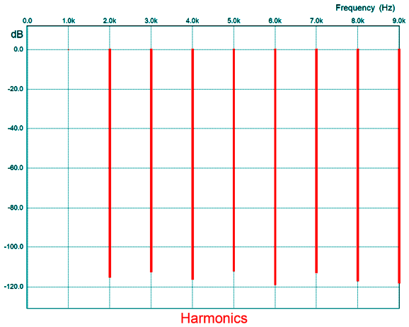
Returning to the pre-preamp circuit, here is the SPICE-generated Fourier graph for 10mV of output signal at 1kHz.
The THD is below 0.0001% in SPICE simulations.
Bastode MC Pre-Preamp
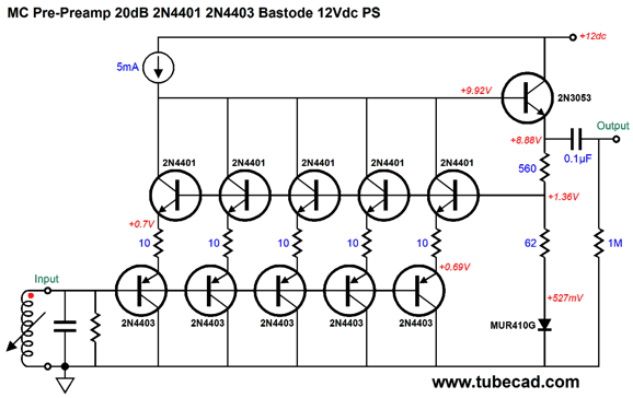
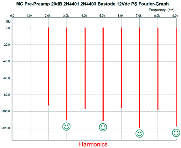
The topology is a bastode circuit with an emitter follower. Five parallel stages lower the noise and the diode gives us a small voltage step-ladder, which allows enough of a voltage drop to use the bastode topology. My goal was only low noise, but when I saw the SPICE-generated Fourier graph for 10mV of output signal at 1kHz I was pleased to see the astoundingly-rare harmonic structure.
Note that the odd harmonics are more attenuated than the even harmonics. Nice.
Berglund's Six-Transistor MC Pre-Preamp
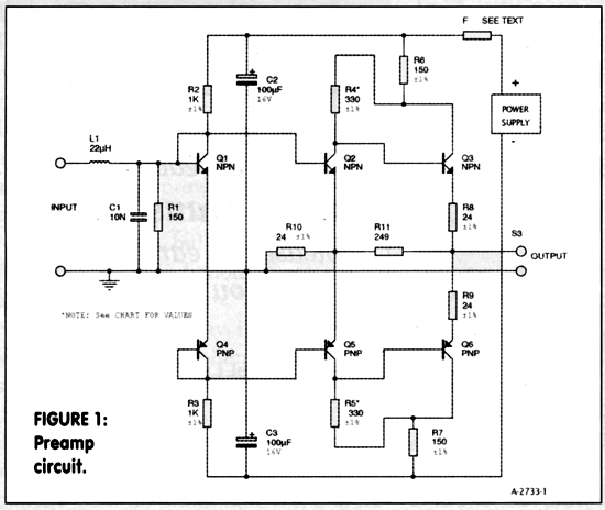
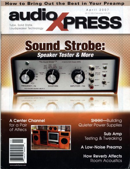
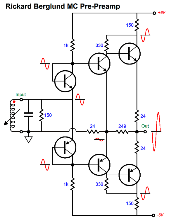
I sort of came close, but not quite, as this circuit does not invert the phase, but the original did. Here is Rickard Berglund's six-transistor pre-preamp from April 2007 in audioXpress magazine.
The first thing that should jump at you is that schematic hold a typo. Did you spot it?
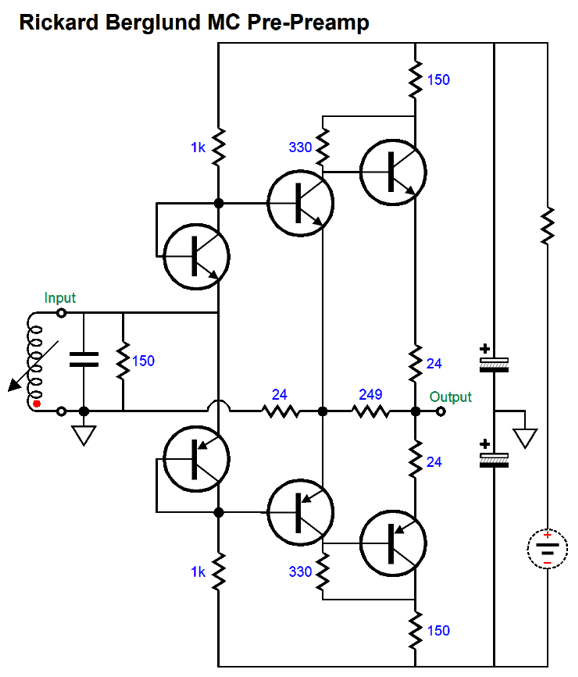
Here is what I am sure the circuit should have looked like.
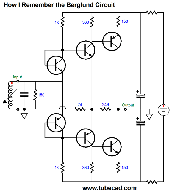
The difference is that where input transistors emitters tie together is actually where the MC cartridge should connect. Berglund states that three feedback loops are employed, but he does not point out that two are positive feedback loops, while only one provides negative feedback, the shared 24-ohm emitter resistor for the second stage transistors. (Actually these transistors are the real first stage, as transistors Q1 and Q4 provide zero gain and only serve as voltage-dropping diodes.) As this circuit inverts the phase, the positive and negative leads to the cartridge should be flipped. If you cannot see how that circuit works, the following schematic might help.
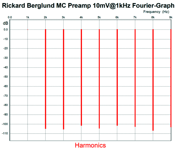
The middle set of transistor function as common-emitter amplifiers, and the rightmost transistors function as emitter followers. In other words, only the middle transistors deliver signal gain, which explains why two positive feedback loops are used. Bear in mind that the cartridge's own resistance will alter the gain. Here is the Fourier graph.
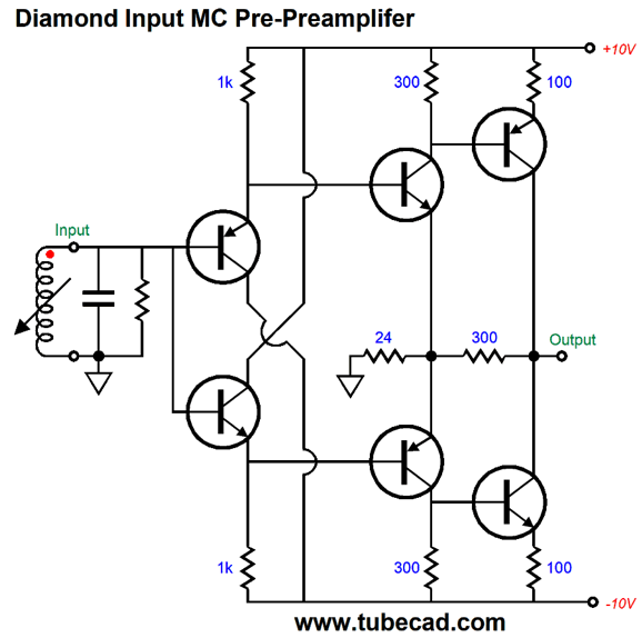
For me, the most interesting part of the circuit is the monopolar power supply, i.e. a power supply that is floating. This setup works due to the transistors Q1 and Q4 working as voltage-dropping diodes in series with two 1k resistors. This string of resistors and diodes defines a two-resistor voltage divider that splits the applied power supply voltage, thereby forcing the circuit to center and create a faux ground, which is helped by the two large-valued capacitors, C2 and C3. In contrast a diamond input stage would not work as well, if at all, with a floating monopolar power supply, as real DC and AC ground is needed. Speaking of diamond circuits, here is diamond-input MC pre-preamp with a gain of 20dB.
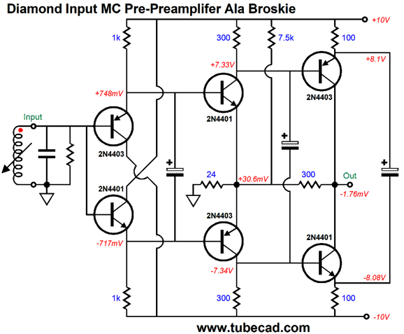
The input transistor function as voltage shifters and the rest of the transistors provide signal gain. This amplifier preserves the input phase at its output. As it stands, the performance is not too bad, but if we apply the following Broskie overlay, the performance improves.
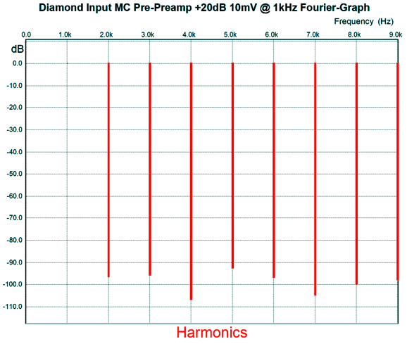
The three added large-valued capacitors both lower the distortion and improve the PSRR. The 7.5k resistor pulls the output back closer to 0V at the output. It is needed as the NPN and PNP matched transistors are never really all that matched, which leads to a DC offset. Before you ask, yes, a DC servo could be added to steer the output back to zero volts. Here is the SPICE-generated Fourier graph for 10mV of output signal at 1kHz for the basic diamond circuit.
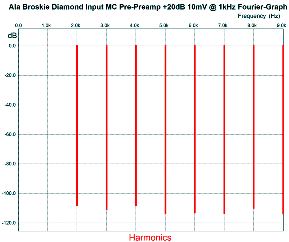
Now, here is the SPICE-generated Fourier graph for 10mV of output signal at 1kHz for the ala Broskie version.
As you can see, there is a substantial improvement.
Ground-Grid Amplifier MC Pre-Preamp
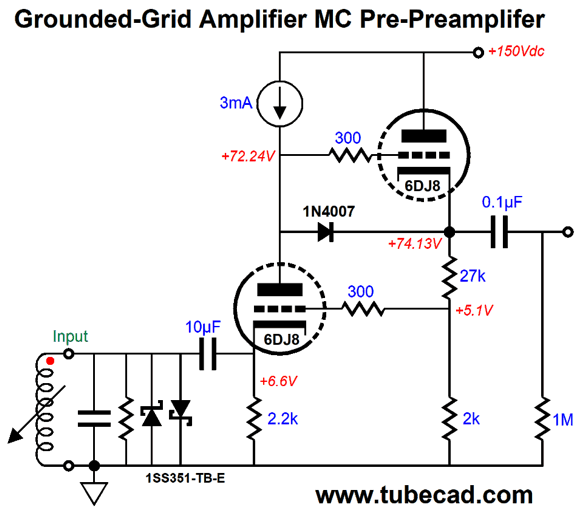
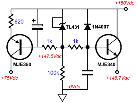
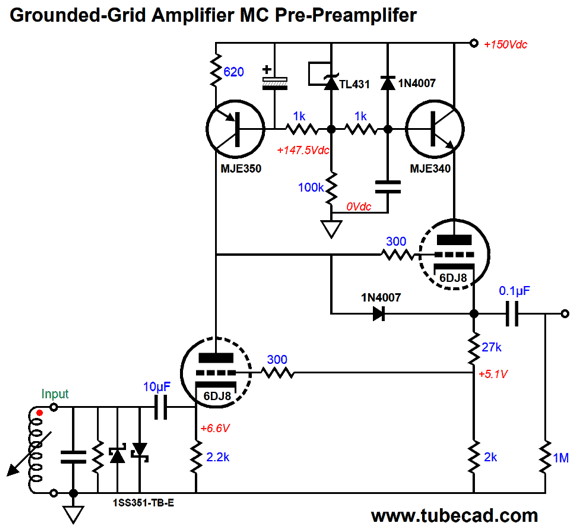
This particular design example presents an input impedance of 2200 ohms. If you expect much lower, then you failed to note the constant-current source loading of the grounded-cathode amplifier. If we add the 6DJ8's plate resistance (rp) to infinity and then divide the sum by the 6DJ8's amplification factor (mu) plus 1, we still get something close to infinity in parallel with the 2.2k cathode resistor, or 2200 ohms. Because 2200 ohms is so high, we can get away with using a 10µF polypropylene input coupling capacitor, rather than the usual electrolytic capacitor. This a huge feature, as electrolytic capacitors leak current but film capacitors don't. The 27k and 2k cathode resistors set the gain to 10X, i.e. 20dB. Now, as we want the quietest MC pre-preamp possible, we must look for possible PSRR enhancements. The constant-current source goes a long way in improving the grounded-grid amplifier. But what about the cathode follower? Remember that a triode's plate is 1/mu as effective as the grid in controlling current flow. In other words, power-supply noise can leak into the output signal through the cathode follower's plate. If a regulated power supply delivers the B+ voltage, then as the circuit stands is good enough. If an un-regulated power supply is used, the following circuit will certainly help.
The MJE350 functions as a constant-current source; the MJE340, an emitter follower. Okay, now let's put it all together.
The funny looking diodes are Schottky diodes, which protect the cartridge from excessive voltage swings from the 10µF input coupling capacitor at both start-up and shut-down. Schottky diodes offer an extremely low forward voltage drop. (As far as I know, the old germanium diodes beat Schottky diodes in this regard.) Okay, we done? No. Being done is not even conceivable. If you seek more MC pre-preamp circuits, check out post 322 and post 323.
Music Recommendation: Bettye LaVette's Here is an analogy: if you attack the king, you must kill him; likewise, if you attempt to sing a royal song, you must kill it. LaVette kills it. She has collected well-known songs from Elton John, Led Zepplin, Moody Blues, Pink Floyd, The Beatles, The Rolling Stones, and The Who. What she does to them is amazingly fine. A good example is a song by the The Who from their Quadrophenia album, "Love, Reign o'er Me." Most covers of this song are boringly derivative, which I would include Pearl Jam's much lauded cover. One interesting cover is by the Italian singer, Graziano Romani, on his album, Graziano Romani Lost and Found: Songs for the Rocking Chairs.
LaVette's cover of "Love, Reign o'er Me" is breathtakingly different. Each word she utters conveys an authentic, genuine, heartfelt emotion that makes the song seem as if she wrote it herself. She transforms Ringo Star's song, It Don't Come Easy, into a kick-ass blues number. Damn, I would love to hear Buddy Guy do a cover of the song following LaVette's lead. The album isn't audiophile grade, alas; but it is A+ artistically rendered. Be sure to give it a listen at Tidal.
//JRB
* Crazy I then went about setting things up properly. Disappointment, as much of the previous magic was gone. I went hunting. One thought I had was that the previously tight speaker cables were ensuring an equally tight connection at both speaker and amplifier terminals. I broke out my socket wrench and went to work. No difference. My next guess was that the open cabinet doors made a difference. They didn't. At the end, I lifted the speaker cables off the floor and held them up with oak pieces of wood. The magic was back. I assumed that I was going crazy, so I called up my friend Gary. Gary listened to floored cables and suspended cables. He, too, heard the magic appear and disappear. He asked what I was going to do. As I removed the wood blocks, I am told him, "Nothing, absolutely nothing. It makes zero sense, so I am going to ignore it."
User Guides for GlassWare Software Since I am still getting e-mail asking how to buy these GlassWare software programs:
For those of you who still have old computers running Windows XP (32-bit) or any other Windows 32-bit OS, I have setup the download availability of my old old standards: Tube CAD, SE Amp CAD, and Audio Gadgets. The downloads are at the GlassWare-Yahoo store and the price is only $9.95 for each program. http://glass-ware.stores.yahoo.net/adsoffromgla.html So many have asked that I had to do it. WARNING: THESE THREE PROGRAMS WILL NOT RUN UNDER VISTA 64-Bit or WINDOWS 7 & 8 or any other 64-bit OS. One day, I do plan on remaking all of these programs into 64-bit versions, but it will be a huge ordeal, as programming requires vast chunks of noise-free time, something very rare with children running about. Ideally, I would love to come out with versions that run on iPads and Android-OS tablets.
|
Special Thanks to the Special 85!
I am truly stunned and appreciative of their support. In addition I want to thank the following patrons:
All of your support makes a big difference. I would love to arrive at the point where creating my posts was my top priority of the day, not something that I have to steal time from other obligations to do. The more support I get, the higher up these posts move up in deserving attention. Only those who have produced a technical white paper or written an article on electronics know just how much time and effort is required to produce one of my posts, as novel circuits must be created, SPICE simulations must be run, schematics must be drawn, and thousands of words must be written. If you have been reading my posts, you know that my lifetime goal is reaching post 1,000. I have 523 more to go. My second goal is to gather 1,000 patrons. I have 915 patrons to go.
The Tube CAD Journal's first companion program, TCJ Filter Design lets you design a filter or crossover (passive, OpAmp or tube) without having to check out thick textbooks from the library and without having to breakout the scientific calculator. This program's goal is to provide a quick and easy display not only of the frequency response, but also of the resistor and capacitor values for a passive and active filters and crossovers. TCJ Filter Design is easy to use, but not lightweight, holding over 60 different filter topologies and up to four filter alignments: While the program's main concern is active filters, solid-state and tube, it also does passive filters. In fact, it can be used to calculate passive crossovers for use with speakers by entering 8 ohms as the terminating resistance. Click on the image below to see the full screen capture. Tube crossovers are a major part of this program; both buffered and un-buffered tube based filters along with mono-polar and bipolar power supply topologies are covered. Available on a CD-ROM and a downloadable version (4 Megabytes). |
||||||||||||||||||||||||||||||||||||||||||||||||||||||||||||||||||||||||||||||||||||||||||||||||||||||||||||||||||||||||||||||||||||||||||||||||||||||||||||||||||||||||||||||||||||||||||||||||||||||||||||||
| www.tubecad.com Copyright © 1999-2019 GlassWare All Rights Reserved |
