| John Broskie's Guide to Tube Circuit Analysis & Design |
|
06 February 2020 Post 491
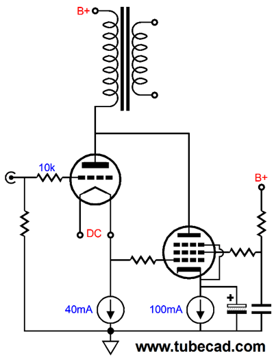
Super Triode with Pentode
We waste a lot of power, however, in the circuit shown above. The 300B does not power the loudspeaker at all, not at all, as its cathode is in series with a constant-current source, and the 100mA constant-current source drops a big DC voltage, which must dissipate plenty of wasted heat. The alternative I am about to show is far more efficient.
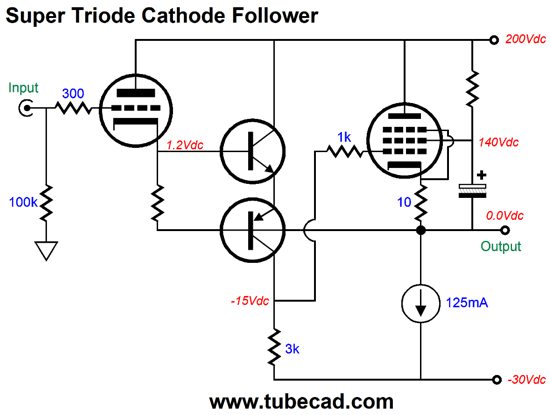
The triode does not have to be a power tube. In fact, a high-mu, high-transconductance triode works best, such a 6DJ8, 6N1P, ECC99. The NPN and PNP transistors form a bastode amplifier with the 3k collector resistor, whose input signal is any voltage variation across the 140-ohm cathode resistor. In other words, the bastode gain stage works to ensure a constant-current flow through the triode by varying its current conduction, which in turn will vary the pentode's current conduction. In other words, the triode controls the pentode through the bastode stage. The constant-current source loads the pentode and creates a single-ended output stage. The following design example shows a unity-gain power buffer for driving low-impedance headphones.
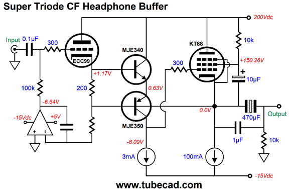
The ECC99 and KT88 make an interesting pairing. The OpAmp forms a DC servo that centers the output stage a 0Vdc. So why have coupling capacitors? When the tubes are either cold or missing from their sockets, nothing will stop the output from slamming down to the negative power-supply-rail voltage; not good. An alternative workaround would be to use a relay and voltage window comparator circuit that would only connect the headphones when the DC offset disappeared. On the other hand, non-polarized electrolytic capacitors sound good, especially those made by Panasonic. Frosting on the cake would be the 1µF film or PIO bypass capacitor. Because this is a single-ended buffer, which by necessity must run in strict class-A, the maximum output voltage is set by the 100mA constant-current source and the external load impedance. For example, with 50-ohm headphones, the most we could ever hope to realize is 5Vpk of output voltage swing, which would equal 250mW of power. Okay, can this approach to super-triode operation be scaled up to create an OTL output stage capable of driving loudspeakers? Here was my first take.
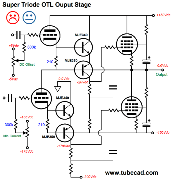
The assumption here is at power pentode such as the 6GC6/El509/PL509 would be used as the output pentodes and that several would be placed in parallel. The reason behind the unhappy face is that I assume that setting the DC offset and idle current would prove a major pain, as the slightest change in the potentiometers would result in big shifts in both DC offset and idle current. Moreover, even if we managed to hit our targets, the output stage might drift off them as the transistors warm. A better solution would be to use a DC servo to eliminate the DC offset and a coupling capacitor and bias potentiometer for the bottom output pentode(s).
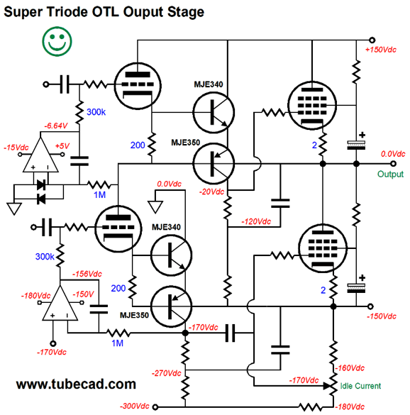
The top DC servo centers the output stage at 0V, while the bottom DC servo centers the bastode's output voltage at a target voltage. The idle current is set by the potentiometer. The set procedure would be to first adjust the idle current and then wait as the DC servo eliminates the DC offset. For better performance, we could replace the two collector resistors in series with a single constant-current source. Another performance enhancer might be to place one or more diodes in between the NPN and PNP transistor emitters, as that would allow us to use a larger valued cathode resistor on the triodes. The biggest performance enhancement would derive from using many output pentodes in parallel.
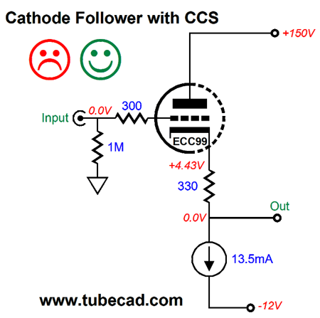
Cathode Followers with CCCS
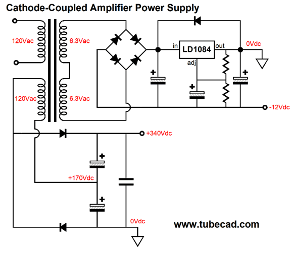
If we do not need that much high-voltage, we can use a full-wave bridge rectifier instead.
Here in North America, Central America and the north part of South America, 120Vac is the wall voltage, which will rectify up to about 168Vdc. Well, this flat-pack-based power supply comes in handy for powering a cathode follower circuit. Why would anyone want a single cathode follower? Most DACs put out over 2Vpk of output signal, and most power amplifier only need 1Vpk to achieve full output. In other words, you may not need any gain in your system, but you might need the higher current delivery of the cathode follower to drive long runs of interconnect or power amplifiers with an unusually low input impedance.
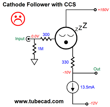
The unhappy face warns us that this circuit should never be used with DC-coupled solid-state amplifiers, as the output will slam to the negative rail voltage at startup or when the tube is missing from its socket.
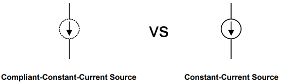
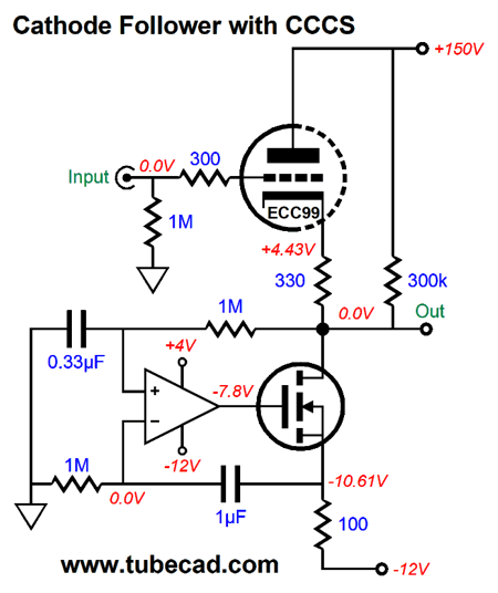
On the other hand, if the power amplifier is tube-based, we can probably get away with no output coupling capacitor, as the tube power amplifier will have to warm up itself. Nonetheless, a safer approach is to use one of my CCCS (complaint-constant-current sources) instead of a plain constant-current source.
The CCCS only matches the current flow through the triode, rather than abide by a preset current; thus, the "complaint" title. At the same time, the CCCS acts as a DC servo that eliminates the DC offset at the output. The 300k resistor gives the MOSFET a current path to the B+ voltage when the triode is either cold or missing from its socket.
The CCCS's idle current falls to just 0.5mA with no triode; and then climbs to 13.4mA, with the triode engaged. The OpAmp should hold an FET input stage and MOSFET that I used in SPICE simulations was a Zetex 2N7000. The OpAmp's negative power-supply pin attaches to the -12V power-supply rail, while its positive power-supply pin attaches to the a +4Vdc power-supply rail. Where do we get this rail voltage, as the flat-pack power supply only shows a B+ voltage and -12Vdc rails? The answer is that we tap off the rectified DC voltage that feed the LD1084 positive voltage regulator.
Remember that the regulator's output is grounded, so the raw DC voltage entering the regulator input must be at some voltage greater than 0V. In other words, a voltage freebie.
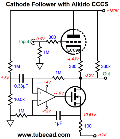
One potential problem we face is excessive noise. Remember, a cathode follower's PSRR is at its worst with a constant-current source loading of its cathode, where the B+ voltage ripple is reduced by only 1/mu. We could use a high-voltage regulator, but that is a hassle. Here is my Aikido-mojo inspired workaround.
A sampling of the power-supply noise is injected to the OpAmp's non-inverting input, so this noise will be superimposed across the MOSFET's source 100-ohm resistor, thereby creating an in-phase varying current flow that matches that experienced by the triode due to the ripple. In other words, the triode pull up, but the CCCS pulls down by an equal amount, so no noise appears at the output. Dang sneaky, don't you think? By the way, if you don't use a regulator on the negative power-supply rail, the Aikido mojo I unlikely to obtain. Note the 0.33µF and 1µF values. These are important, as we do not want to create a bass hump at some subsonic frequency.
Five Fullrange Driver Loudspeaker
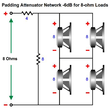
The 8-ohm resistor in parallel with the series-parallel four fullranges combines to form a 4-ohm resistance, while the 4-ohm resistor brings the load impedance up to 8 ohms. The attenuator's output impedance is 2.66 ohms. I would do it differently. (Can you imagine me not doing it differently?)
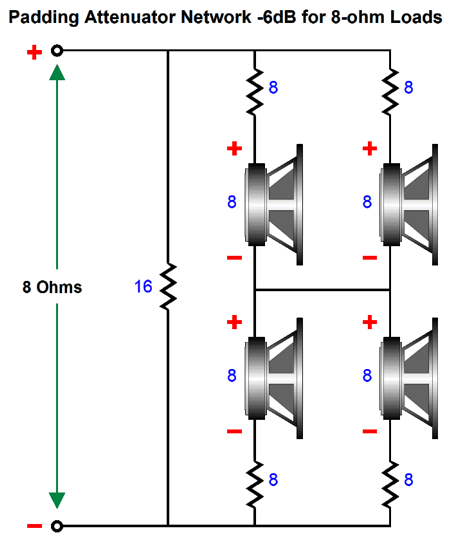
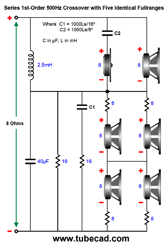
Each fullrange gets its own series 8-ohm resistor, effectively bringing each fullrange driver up to 16 ohms. Thus, the combined series-parallel resistance would be 16 ohms. We then place the 16-ohm resistor in parallel and get an 8-ohm total resistance. Wouldn't the 8-ohm series resistors ruin the fullrange's bass response? No. In fact, it would improve it. Here is why: most woofers and fullranges were designed to work in either an acoustic-suspension or bass-reflex enclosure, which will cause the driver Qts to increase. Unfortunately, such drivers do not work well in dipole loudspeaker, as the driver's over-damped Q creates a pinched bass response. In other words, we need a Qts between 0.7 to 1.2 to reproduce lower frequencies. Adding the 8-ohm series resistor will increase the driver's Qes and, in turn, Qts. In post 396, you will find the following formulas: Qes (new) = Qes*(R + RDC) / RDC Qes electrical part of woofers Q-Factor, R = added resistance To find Qts, we multiply Qes by Qms. The 500Hz crossover is a series type, but with a twist. The twist that the high-frequency fullrange gets a Zobel network made out of a back-firing tweeter and capacitor, rather than the regular capacitor and resistor pairing.
All the resistor must be high-wattage types. I like the non-inductive types made by Mills. By the way, by inspecting the formulas, you see that a Zobel network's capacitor is found by dividing the driver;s inductance (Le) by the drivers impedance squared; then we multiply the result by 1000 to get the millihenry value. Be warned: some speaker makers publish the voice-coil's inductance outside the magnet structure, which is only fraction of its actual inductance in the finished speaker driver.
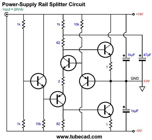
Power-Supply Rail-Splitter Circuit
Starting at the left, we see a 24Vdc mono-polar power supply working into a two-resistor voltage divider made up of the two 1k resistors, which evenly split the 24 volts. An emitter-follower buffer then drives the bastode's non-inverting input; moreover, the PNP transistor drops its base voltage at its emitter. At the heart of the circuit is a bastode gain stage made up of the NPN and PNP transistor in series. This DC voltage shift allows us to exploit the bastode circuit, as its inverting and non-inverting inputs differ in DC voltage. The bastode gain stage then drives two NPN transistor power transistors in a push-pull fashion. A PNP transistor relays the output to the bastode's inverting input, completing a 100% negative feedback loop. If a positive pulse were injected into the rail-splitter's output, the bastode circuit's current conduction would increase, causing the top output power transistor to reduce its current conduction and the bottom output transistor's to increase, allowing both output transistors to buck the positive pulse. Here is the same circuit, but with fleshed out details.
The 100-ohm potentiometer allows us to adjust the actual DC voltage splitting. The MJL3281A are beefy power transistors in the TO-247 package. In SPICE simulations, the circuit shown above worked quite well. If you have an excellent memory, you might remember me writing about a vacation my wife and I once enjoyed in Canada that I mentioned in post 323. Here is a quote:
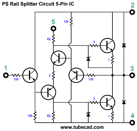
Since then, I have kicked myself for not delivering him a long list of potential IC circuits. Well, this rail-splitter circuit is a good candidate for translation into a five-pin IC in the TO-220 package.
The six transistors and eleven resistors and two diodes and two zeners form the basis of the circuit. The rest of the needed parts would be added externally to the IC, which would allow us to use large capacitors and a potentiometer.
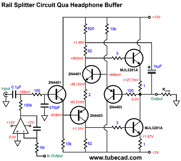
In addition, we could set the idle current flow through the two output NPN transistors by choosing the resistor value for the resistor that bridges pin-5 to pin-2; the larger in value, the less the current flow. The zeners limit the maximum output current flow, which would come in handy if pin-3 (the output) ever shorted to pin-2 or pin-4. The two diodes protect the circuit from inductive voltage kickbacks. As I looked over this potential IC, I wondered what other uses I could find for it. Effectively, the circuit is a unity-gain power buffer, so why not make an audio-grade buffer out of it, one suitable for driving headphones? My big fear would be DC offsets, which explains why I added the DC servo to the following circuit.
The OpAmp runs off the +/-12Vdc power-supply rails. The 100-ohm resistor and 470pF at the input define a low-pass filter at 3.38MHz. The idle current through the output NPN transistors is 128mA, which implies a peak class-A current swing of 256mA. With 32-ohm headphones, the peak voltage swing would equal 8.192Vpk, which results in 1W of power. In SPICE simulations, the buffer performed well. Here is the Fourier graph for 1Vpk at 1kHz into 32-ohms.
Not bad. The THD is about 0.01% Here is the graph for 4Vpk of output, which is thunderously loud, as it translates as 250mW.
Still not bad. The THD has climbed to about 0.1%. Note that the single-ended look of the harmonics and that the 3rd and 5th seem extra down relative to the 2nd, 4th, and 6th harmonics.
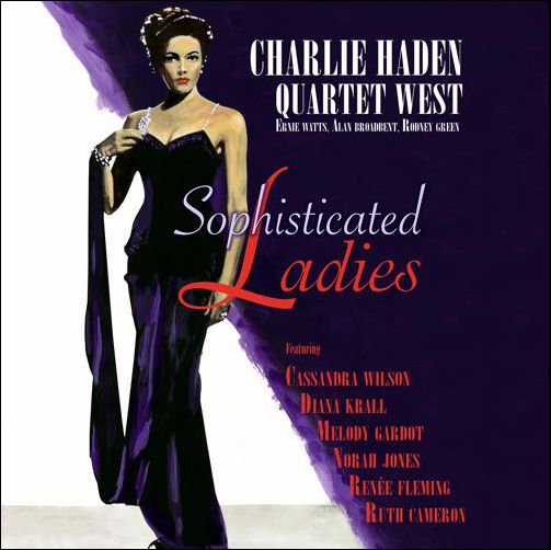
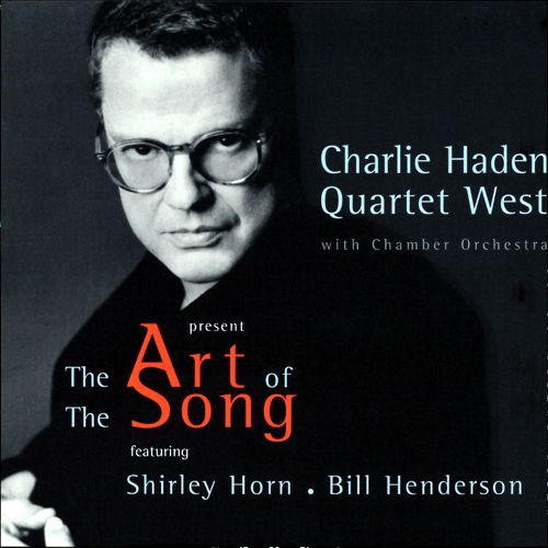
Music Recommendation: Charlie Haden's Sophisticated Ladies Haden, back in 1999, released a similar album with Bill Henderson and Shirley Horn, The Art Of The Song.
This album is well worth a listen. Both are available at Tidal. While you are at it, hunt down at Tidal the cover of the classic song, The First Time Ever I Saw Your Face,
by Rafiq Bhatia and Cécile McLorin Salvant. It was listed under Bhatia's album, Standards Vol. 1. Not your father's version, but interesting nonetheless. //JRB
User Guides for GlassWare Software
For those of you who still have old computers running Windows XP (32-bit) or any other Windows 32-bit OS, I have setup the download availability of my old old standards: Tube CAD, SE Amp CAD, and Audio Gadgets. The downloads are at the GlassWare-Yahoo store and the price is only $9.95 for each program. http://glass-ware.stores.yahoo.net/adsoffromgla.html So many have asked that I had to do it. WARNING: THESE THREE PROGRAMS WILL NOT RUN UNDER VISTA 64-Bit or WINDOWS 7 & 8 or any other 64-bit OS. I do plan on remaking all of these programs into 64-bit versions, but it will be a huge ordeal, as programming requires vast chunks of noise-free time, something very rare with children running about. Ideally, I would love to come out with versions that run on iPads and Android-OS tablets.
//JRB
|
|
I know that some readers wish to avoid Patreon, so here is a PayPal button instead. Thanks. John Broskie Special Thanks to Francis Oconnor
John Gives
Special Thanks to the Special 84
I am truly stunned and appreciative of their support. In addition I want to thank the following patrons:
All of your support makes a big difference. I would love to arrive at the point where creating my posts was my top priority of the day, not something that I have to steal time from other obligations to do. The more support I get, the higher up these posts move up in deserving attention. If you have been reading my posts, you know that my lifetime goal is reaching post number one thousand. I have 509 more to go. My second goal was to gather 1,000 patrons. Well, that no longer seems possible to me, so I will shoot for a mighty 100 instead. Thus, I have 16 patrons to go. Help me get there.
Only $12.95 TCJ My-Stock DB
Version 2 Improvements *User definable Download for www.glass-ware.com |
||


| www.tubecad.com Copyright © 1999-2020 GlassWare All Rights Reserved |