| John Broskie's Guide to Tube Circuit Analysis & Design |
|
27 March 2020 Post 497 (3 to go to 500)
I am struggling to post shorter post more often, so you all have something read while quarantined at home. But dang, is it difficult to write less. It's not just pictures that are worth a thousand words, as schematics are laden with significance—and there are so many schematics to show.
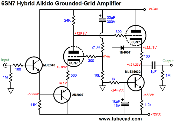
DC Coupled Cathode Follower
The more I looked at the schematic, the more I began to question it. What if we moved the output coupling capacitor to inside of the circuit? What if we then DC couple the cathode follower's output? Such changes would allow us to get away with using a much smaller coupling capacitor value.
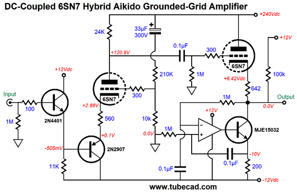
Why the two faces in opposition? The circuit looks like it should work perfectly; it passes all its simulations in SPICE. The potential problem is that we do not know what sort of power amplifier the line-stage amplifier will drive. The power amplifier makes a difference. If the power amplifier holds an input coupling capacitor, we might be safe. If the power amplifier is tube-based, we probably will be safe. If the power amplifier is solid-state design with DC coupled input, we are doomed. How so? At start-up, when the cathode follower's triode has yet to conduct, the constant-current source will pull the output down to the negative power-supply rail voltage. Not good. One workaround would be to use a relay to short the output to ground until the triodes fully conduct. This might work, but with the output grounded by the relay, the DC servo cannot provide accurate DC grid voltage, as any voltage still delivers zero DC offset as long as the relay shunts the output to ground. In other words, we would be likely to get a nasty voltage bump after the relay opens. A further workaround would be to place series output resistor between the cathode follower's output and the relay's contact, say 100 ohms. This workaround would give the DC servo an actual DC output voltage to control. Or, we could simply add a diode.
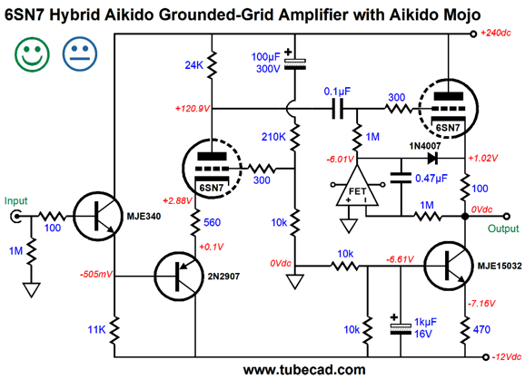
At start-up, the tube has yet to conduct, but the OpAmp has. The OpAmp strives to establish no DC offset at the output. The constant-current source pulls down, so the OpAmp's output swing up until the diode becomes forward biased and conducts, bridging the OpAmp's output to the top of the cathode resistor. The OpAmp then pulls up on the resistor until the output voltage centers a zero volts. As the tube heats, the cathode follower slowly comes to life, helping the OpAmp pull the cathode resistor up, until the triode takes over, and the diode ceases to conduct. This is an example of how art enters electrical engineering. The diode solution works in this specific circuit, but not in other circuits. Indeed, it wouldn't work with a circuit based on the exact same topology, but differed in power-supply voltage and part selection. For example, a B+ voltage of 120Vdc and a 6DJ8 tube wouldn't work. The subtle difference is that 240Vdc B+ voltage and the 6SN7 tube with is 100-ohm cathode resistor and the constant-current source's 10mA idle current all work to create the need for a large negative bias voltage, from grid to cathode, for the cathode follower's 6SN7, i.e. -7Vdc. To this we add the diode's turn-on voltage of about 0.7V, making a total of 7.7V. This relatively large voltage defines the limit to the line-stage amplifier's potential peak output-voltage swing. Since most line-stage amplifiers are seldom required to put out any voltage greater than 3V, we are safe. The reason I included the uncommitted face on the schematic was that I would have to see the actual output at start-up. Will it be a flat-line at 0V or bump or a slow-moving sinewave that tapers down to a flat-line? In contrast, if the needed bias voltage is too small, the DC servo will clip large negative-going voltage swings. The workaround would be to use a Broskie DC servo circuit instead.
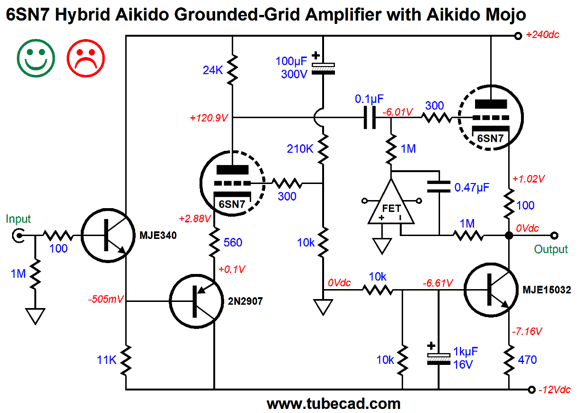
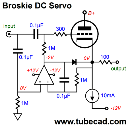
This DC servo tracks the input signal, so the OpAmp's output voltage is always at the same negative voltage realtive to the cathode voltage in spite of big signal swings. Another solution is to use one of my signature compliant constant-current sources (CCCS) that do not set a predefined current flow, but match whatever current flow it encounters, yet offer a supremely high output impedance. This circuit functions much like an inductor, but with the added advantage that it can eliminate DC offset voltages.
The cathode follower's 6SN7 will idle at whatever current flow works for that individual 6SN7 with a 642-ohm cathode resistor terminating into 0V. The compliant constant-current source works to eliminate any DC offset voltage, a state only accomplished when its output current flow pulls the DC output voltage to zero volts. The 100k resistor that bridges the output to the +12V power-supply rail gives the compliant constant-current source something to bite on when the triode is still cold or missing from its socket. How does the compliant constant-current source work? If the output's DC offset strays positively, the OpAmp's non-inverting input will see the positive voltage, which forces the OpAmp's output to swing up positively, which in turn will prompt the NPN transistor's conduction to increase, pulling down the DC output voltage back to 0V. Conversely, a negative DC offset forces the OpAmp's output to swing down negatively, causing the NPN transistor's conduction to decrease, allowing the triode to pull up the DC output voltage back to 0V. Audio signals are ignored, as the 1meg resistor and 0.1µF capacitor form a 1.6Hz low-pass filter. The OpAmp's inverting input sees the opposite, as its 1meg resistor and 0.47µF capacitor form a 1.6Hz high-pass filter that allows all of the AC audio signal present on the top of its emitter resistor to be relayed to the inverting input. The result is that the OpAmp will strive to maintain a steady, fixed, close to constant-current flow through the resistor, creating a hugely high output impedance at the transistor's collector. One easily made mistake would be to terminate the 0.1µF capacitor that attaches to the non-inverting input to ground, rather than the negative power-supply rail as shown in the schematic. Don't. If the capacitor terminated into ground, the circuit would work flawlessly in SPICE simulations, but not in reality. In SPICE, voltage sources are perfect; in reality, power-supply rail voltages are contaminated with noise, such as ripple and signal-induced voltages. With the capacitor terminated into the negative power-supply rail, these noises are ignored; with the capacitor terminated into ground, these noises are amplified. Another potential mistake is to replace the 0.47µF capacitor with another 0.1µF capacitor. Don't. The staggered values result in a flat low-frequency response. In contrast, using the same valued capacitors creates a subsonic bass hump. This also holds true for the simple DC servo version, where the 0.1µF internal coupling capacitor and the 0.47µF DC servo capacitor work as a team. (On the other hand, if you know what you are doing, you could purposely introduce a few dB bass hump at 40Hz and thrill your friends with the heft and extension of the bass.) No doubt, some are wondering if this elaborate trip was actually necessary. Is using a smaller-valued coupling capacitor all that that important? Well, a lot depends on how expensive a coupling capacitor you are used to buying, as some cost hundreds of dollars. Nevertheless, I see your point. In fact, I myself would opt to use the output coupling capacitor when using the circuit as a line-stage amplifier. On the other hand, if you are driving low-impedance loads, such as 600-ohm input impedances, this circuit looks far more promising. Here is an interesting example based on the topology: a tube headphone amplifier.
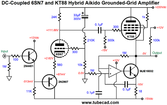
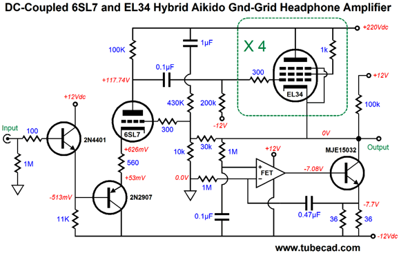
A mighty KT88 (or KT66 or KT120…) is used in the cathode follower position. The cathode follower's idle current increases to a little over 100mA. No cathode resistor is used. The negative power-supply rail voltage is increased to -15Vdc. The result of these changes is that we can now drive 300-ohm headphones, such as those made by Beyer and Sennheiser. If lower impedance headphones need to be driven, we could place more output tubes in parallel. Imagine four EL34 output tubes per channel, each idling at a tad less than 60mA. A total idle current of 240mA would allow peak output voltage swings of 7.8V into a 32-ohm impedance. The output impedance would be about 20 ohms. If we desired a lower impedance, we could replace the 6SN7 with a higher-mu triode, such as the 6SL7 or 12AT7, and add a negative feedback loop.
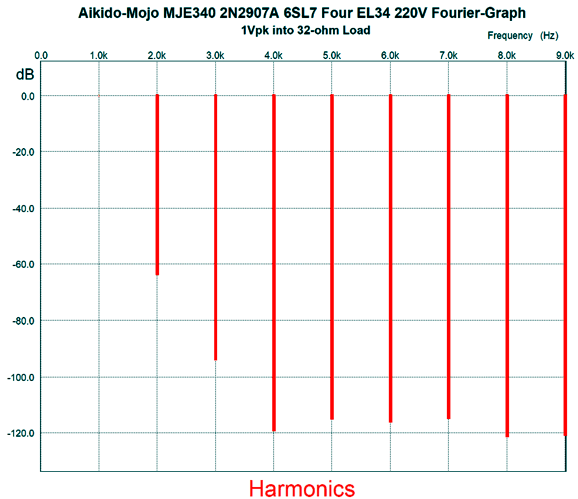
The Aikido-mojo resistor and capacitor are still in place with the 430k feedback resistor and the 1µF capacitor. Here is the SPICE-generated Fourier graph.
Okay, does it make any sense to run eight EL34 tubes, with total of 100W of heat dissipation, just to drive low-impedance headphones? It depends. First of all, your low-impedance headphones might not require anything near 7Vpk of voltage swing. For example, an iPod puts out 1Vpk. If so, you could use only two EL43 tubes per channel. On the other hand, the EL34 tubes will probably last a decade, as the relatively low B+ voltage and relatively low dissipation will greatly extend their life. Moreover, EL34s, even the best ones, are relatively cheap compared to 300B and other exotic output tubes. (To be frank, the best triode-connected pentode would probaly be the EL86, as it can deliver a lot of current with little B+ voltage.) Just imagine the bragging rights, as you show off your direct-coupled OTL headphone amplifier, with its phalanx of eight output tubes.
More Phono Preamp Philosophy
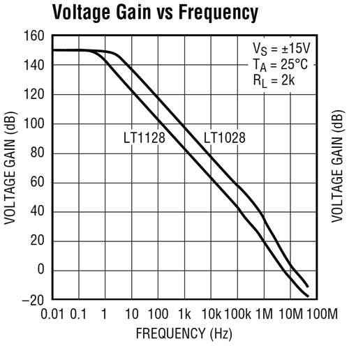
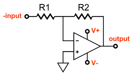
The LT1128 is a low-noise design whose input DC offset voltage is measured in mircovolts, not millivolts. It open-loop DC gain of 150dB translates into a ratio of one to thirty million. In addition, the OpAmp can run of +/-22Vdc bipolar power supply rails and is unity-gain stable. If we wanted to maintain something close to a constant negative feedback ratio across the audio bandwidth with this OpAmp, we should run it in an inverted mode and impose a low-pass output by shunting its negative feedback resistor with a capacitor.
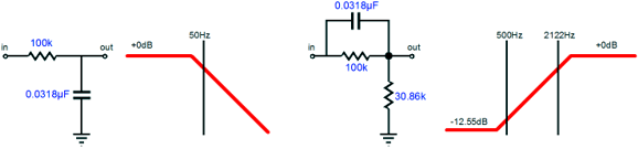
We could set the filter frequency to 2122Hz, the second half of the RIAA equalization curve. The problem is that we would stray too far from a constant negative feedback ratio across the audio bandwidth, as frequencies between 1Hz and 2122Hz would see varying negative feedback ratios. If we used 50Hz instead, we would get much closer to a constant negative feedback ratio across the audio bandwidth. The remaining task would be to further equalize the signal to match the entire inverse RIAA equalization curve. In other words, we need to boost the frequencies from 500Hz to 2122Hz by 12.55dB. Fortunately, well at least for me, I covered how this is done back in post 118, under the topic heading of Alternate Approach to RIAA EQ.
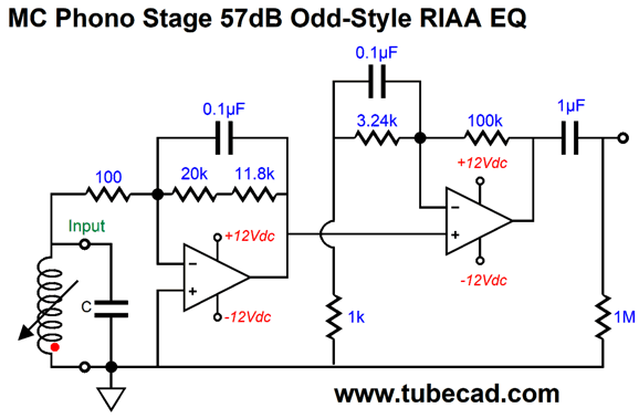
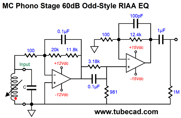
Here is how we could achieve this end with two OpAmps.
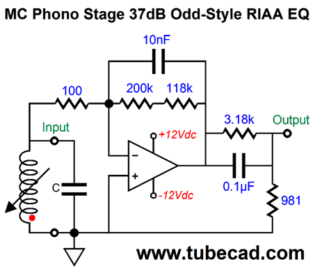
The input OpAmp deliver a gain of 319 or 50dB for frequencies below 50Hz. The second OpAmp provides more gain and the boost the frequencies from 500Hz to 2122Hz by 12.55dB. The result a flat frequency output. Note that the first OpAmp in configured in the inverting arrangement, but the output OpAmp is non-inverting, so we need to flip the phono cartridge's wires to set the phase back to normal. As far as the moving-coil cartridge is concerned, it is loaded by a 100-ohm resistance, as the OpAmp's inverting input acts as a virtual ground. Ever since John Linsley Hood recommended the inverting OpAmp topology for phono preamps decades ago in HiFi World magazine, I tried it and found that the slight increase in noise was compensated by a more natural sonic presentation. We can use a passive equalization network to introduce the 500Hz to 2122Hz boost.
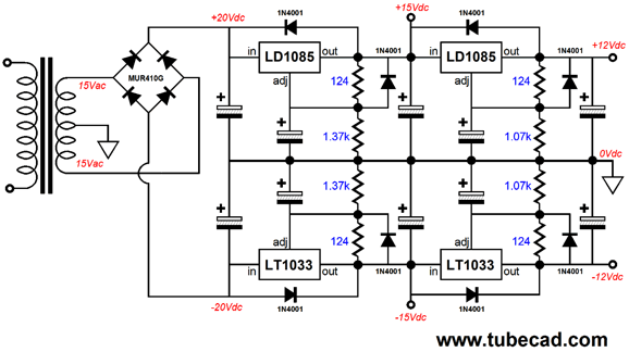
The output OpAmp runs in non-inverting mode. It must offer enough gain to overcome the insertion loss of -12.55dB imposed by the passive equalization network and whatever additional gain is required. The 100pF capacitor shunting the negative feedback resistor is there to stabilize the OpAmp at ultra-high frequencies. Of course, some OpAmps do not need this capacitor. Note that the second OpAmp runs off +/-15Vdc power-supply rail voltages, while the first OpAmp runs off +/-12Vdc rails. What is going here? The idea is that we would cascade voltage regulators so the first OpAmp, which is the critical one in terms of noise, gets the cleanest power-supply voltages.
In fact, I would use an RC pre-filters on the 15V regulators. If you look at the data sheet for three-pin adjustable voltage regulators, you will see the graph that shows the regulator's PSRR versus frequency. There you will see that the deepest power-supply noise rejection occurs at about 100Hz to 200Hz, where the ripple frequency lies. The low-pass RC filter strips away much of the high-frequency noise, so the regulator has far less work to do. Because the OpAmps draw so little current, the RC resistor value can be large without limiting the regulator input voltage. Here is a standalone phono preamp that completes the entire RIAA EQ, which could then cascade into a tube gain stage for the extra needed gain.
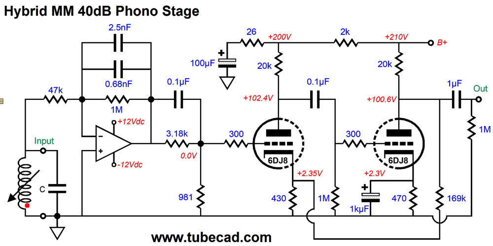
Obviously, I would use an Aikido gain stage based 12AT7 tubes, but many more tube circuits are possible. Here a moving-magnet cartridge version that uses a two-stage negative-feedback arrangement.
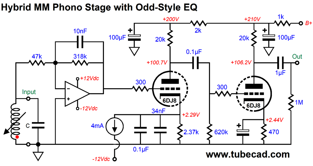
The tube gain stage with a flat frequency response. The 169k negative-feedback resistor sets a high gain, which is needed to boost the output level to +40dB. Note that this resistor DC couples to the output triode's plate. We can get away with the DC connection as the gain is so high and the 6DJ8 draws so much current. The next design won't make sense to many. What is going on here is the 500Hz to 2122Hz boost is accomplished by the input triode.
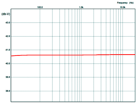
Note the crazy-high cathode resistor value, i.e. 2.37k. The shunting 0.134µF capacitor takes effect at 500Hz and flattens at 2122Hz. In other words, the triode presents two gains: a lower gain below 500Hz and a higher gain above 2122Hz. Here is the entire phono preamps's frequency graph.
My fear is that preamp's flatness relies on the 6DJ8's electrical characteristics, which are from being as consistent as a 0.1% resistor's value. In other words, I could have added the dreaded "SPICY" label.
At the same time, the idea is fascinating and is made possible due to the constant-current source and the -12Vdc power-supply rail.
Music Recommendation: Sinfonietta My guess is that if you like Antonín Dvořák's music, you will like this work by Janácek. (Since both were Czech composers, both born in the nineteenth century, this makes sense.) By the way, if you don't know Dvořák's Tone Poems, you should check them out. Alas, Tidal, being Tidal, makes a complete mess of classical music. (They seem blind to the difference between composer and conductor and orchestra.) Thus, if you search "Antonín Dvořák," the tone poems won't show up. The same holds true for searching "Antonin Dvorak," although a different group of albums show up. If you search Google for "Dvořák," you get results that include "Dvorak" or "Davorack." This is due to a database function labeled "sounds like," which was created to perform quality searches in spite of variations or errors in spelling. Tidal hasn't discovered this programming function. To find the Tone Poems you must search either "Dvorák: Tone Poems " or "Dvořák: Complete Symphonies; Tone Poems." Give his tone poem, The Noonday Witch, a listen. Lovely music. Speaking of tone poems, did you know that Frank Sinatra released an album in 1956, Frank Sinatra Conducts Tone Poems of Color, where he conducted an orchestra as it performed a set of 12 compositions by eight composers—each composition is devoted to one color; unlike people of color, white is included. (I couldn't resist. Consider this an ex post facto trigger warning.) Be sure to give each track a listen, as they vary greatly.
Tidal comes to the rescue with this one; just search "Sinatra Tone Poems." Returning to Leos Janácek's composition, Sinfonietta, I have noted that Janácek isn't everyone's first choice in listening, but when I encounter a big fan of his compositions, he usually turns out to be vertiginously intelligent. (Recently I heard it said that if you don't love Bach, you cannot be a first-rate mathematician.) Another piece I love by Janácek is his Glagolitic Mass, which bears a strong family resemblance to his Sinfonietta. By the way, to find this work at Tidal search "Janácek Sinfonietta." I am a big fan of the Decca/London recording with by Sir Charles Mackerras conducting. Failing that, the Berliner Philharmoniker is closed, but they are offering a free month of streaming. Just register and listen, which includes higher res streaming. I tried it and it was a lot of fun, after I forced Windows to use my USB DAC rather than the laptop speakers. Sir Simon Rattle conducts.
//JRB
User Guides for GlassWare Software
For those of you who still have old computers running Windows XP (32-bit) or any other Windows 32-bit OS, I have setup the download availability of my old old standards: Tube CAD, SE Amp CAD, and Audio Gadgets. The downloads are at the GlassWare-Yahoo store and the price is only $9.95 for each program. http://glass-ware.stores.yahoo.net/adsoffromgla.html So many have asked that I had to do it. WARNING: THESE THREE PROGRAMS WILL NOT RUN UNDER VISTA 64-Bit or WINDOWS 7 & 8 or any other 64-bit OS. I do plan on remaking all of these programs into 64-bit versions, but it will be a huge ordeal, as programming requires vast chunks of noise-free time, something very rare with children running about. Ideally, I would love to come out with versions that run on iPads and Android-OS tablets.
//JRB
|
|
I know that some readers wish to avoid Patreon, so here is a PayPal button instead. Thanks. John Broskie Special Thanks to Francis Oconnor
John Gives
Special Thanks to the Special 84
I am truly stunned and appreciative of their support. In addition I want to thank the following patrons:
All of your support makes a big difference. I would love to arrive at the point where creating my posts was my top priority of the day, not something that I have to steal time from other obligations to do. The more support I get, the higher up these posts move up in deserving attention. If you have been reading my posts, you know that my lifetime goal is reaching post number one thousand. I have 503 more to go. My second goal was to gather 1,000 patrons. Well, that no longer seems possible to me, so I will shoot for a mighty 100 instead. Thus, I have 16 patrons to go. Help me get there.
Only $12.95 TCJ My-Stock DB
Version 2 Improvements *User definable Download for www.glass-ware.com |
||


| www.tubecad.com Copyright © 1999-2020 GlassWare All Rights Reserved |