| John Broskie's Guide to Tube Circuit Analysis & Design |
|
17 June 2020 Post 506
SRPP Driven Zen Amplifier
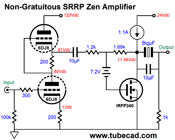
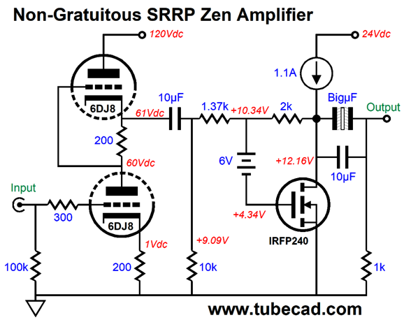
The Zen output stage uses a single power MOSFET and runs in strict class-A, as do all single-ended amplifiers. The constant-current source loading shields the MOSFET from the B+ voltage ripple, which is a plus, as I imagine a 24V switcher power supply being used. The most interesting trick here is the rechargeable NiCad 7.2V battery. The battery allows a voltage shift without using an internal coupling capacitor. Rechargeable NiCad nominally 9V batteries actually come in at 7.2V and 8.4V. One problem with rechargeable batteries is that they discharge far fast then normal alkaline 9V batteries. What about other battery types? Well, CR2032 3V lithium batteries usually have a 10-year life span. Two in series yield 6V. The problem with using the 6V voltage drop is that the output stage won't center at 12V. Here is the workaround.
Note the added 10k resistor. Also note that the 1.2k feedback resistor has been replaced by a 1.37k resistor. Put 10k in parallel with the 1.37k (10000||1370) and we get 1205, which is close enough to 1200 ohms, the optimal value fort his SRPP stage.
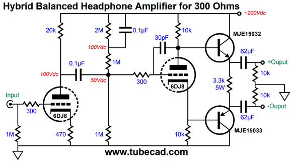
Balanced Hybrid Headphone Amplifier Concisely put: tubes do high-voltage, not high current. On the other hand, solid-state devices can release huge torrents of current. A wimpy power transistor tops out at 10A, a feat that would require fifty 300B tubes in working in parallel. In other words, if you want to deliver big current swings into low-impedance headphones, going hybrid makes sense. Let's start with a simple example.
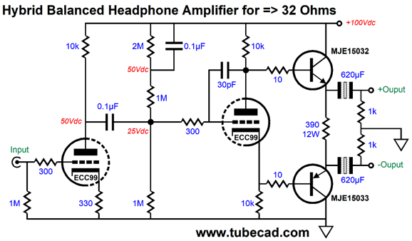
The intended load impedance is 300 ohms. The output transistors idle at 30mA, which imposes a 30mA peak current swing, due to the strict class-A operation. Now, 30mA peak current swings makes 9Vpk voltage swings into 300-ohm headphone drivers. Plenty, in other words. To get something like 4Vpk into 32-ohm loads requires 125mA peak current swings. Note that we need the current more than the voltage. This allows us to halve the B+ voltage, but increase the idle current fourfold.
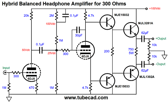
The 390-ohm resistor sees half the B+ voltage and get plenty hot (6.4W); thus, the high wattage ratting. (I had in mind the Vishay Mills MRA series of non-inductive, non-magnetic wirewound resistors. On the other hand, four 390-ohm 3W power resistors could be wired in series/parallel.) The relatively low B+ voltage allows us to use non-polarized electrolytic output coupling capacitors. This is a big bonus, as non-polarized electrolytic capacitors sound better than the typical polarized electrolytic capacitor. Of course, we can and should bypass these coupling capacitor with high-quality film or PIO capacitors. The ECC99 vacuum tube offers lower gain than the 6DJ8 and works well with relatively low plate voltages. Aikido mojo enters the picture by carefully choosing the input triode's cathode resistor value, as we want to force an equal amount of power-supply noise at each of the balanced outputs. If the leaked power-supply noise is in phase and equal in magnitude, the headphone driver will ignore it entirely, as it can only respond to differences. No difference, no sound. Shunting the 2M resistor with a capacitor is also part of the Aikido mojo scheme. (Actually, this more of a habit of mine, as I often use two triodes in totem-pole arrangement for the input stage.) The 30pF capacitor limits the high-frequency response and prevents high-frequency peaking by the transistors. This was also the motive behind the 10-ohm base-stopper resistors. Are we done? Of course, not; we are never done. As I looked over the schematic, I wondered what further hotrodding was possible. Instantly, the following schematic came to mind.
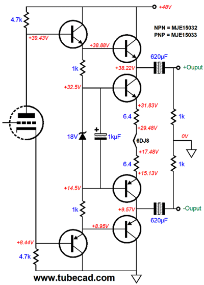
The transistor driver stage unloads the split-load phase splitter and allows us to use beefier output transistors. In many ways, this looks like the output stage of a 100W solid-state power amplifier. The question you should be asking yourself is, Why have we returned to using a 6DJ8 tube? I had a good reason, but let's get there in baby steps. (The late Dr. Gizmo told me that I should print and place a large banner on the wall behind my computer screen that proclaimed, "Baby Steps." He argued that everyone could get there, if we took baby steps.) Okay, the first baby step is to replace the power load resistor with a constant-current source. We could use an LM317-HV configured as a constant-current source. Instead, we will use two extra transistors and smaller-valued load resistor. In addition, we will halve the B+ voltage again.
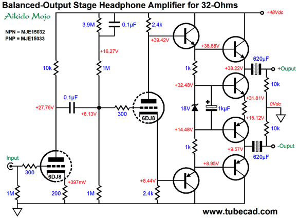
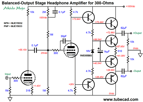
The 18V zener establishes a fixed voltage reference for the two center transistors. Because zeners are famous for being noisy, we shunt it with a large-valued capacitor. Thus, the load resistor in between the two emitters sees a fixed voltage drop, which implies a constant-current flow. In other words, we have a two-direction constant-current source. The top and bottom output transistors must work against this constant-current flow. The entire output stage runs in single-ended mode, in spite of the balanced outputs. By the way, before taking the next step, we will look at a higher-voltage, lower-current version for driving 300-ohm headphones.
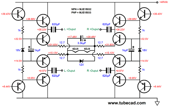
The topology remains the same, but the idle current is lower, while the B+ voltage is higher. In addition, we can use film output coupling capacitors. Okay, now let's think about the previous version that used 6DJ8 triodes and low B+ voltage of only 48Vdc. If we get truly sneaky, we can capture a free DC heater power supply voltage. Free? What do I mean by free? Note the emitter resistor shared by the middle output transistors. What if we replace it with the 6DJ8 heater element?
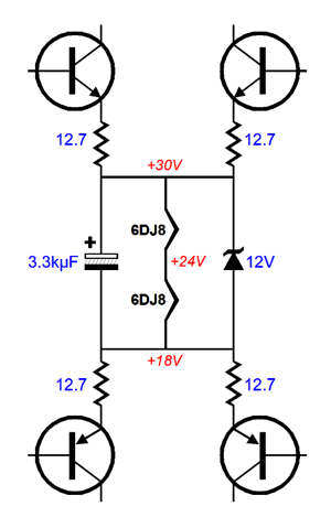
Indeed, what if we replace the resistor with two heater elements in series? A 6DJ8 heater draws 365mA at 6.3V. That is a lot of current, as 365mA against 48Vdc equals 17.5W per channel. On the other hand, what if we let both channels share the two 6DJ8 heater elements? This way we would dissipate 17.5W for both channels, rather than 35W. No external heater power supply, just a B+ voltage power supply.
Just the two solid-state output stages are shown. Note that the 12V zener limits each heater to 6Vdc. Is this a problem? No, in fact, it is blessing, as the slightly lower heater voltage will extend tube life. I have done several experiments with low-voltage operation of tubes, and I have found that that the sound improves with lower heater voltage, say only 5Vdc for a 6DJ8. Why would this be so? My guess is that low plate voltage necessarily means low plate current, so there is no need for the full potential cathode current flow. I have to do more exploration here before I make a hard commitment, but so far the results have been promising.
Due to the strict class-A operation of both channels, the heater elements do not see any of the audio signal currents. As far as the heaters are concerned, they are in series with two fixed current flows. Thus, we make double use of the high current flow through the two output stage, as we obtain free heater voltage.
EMI Line-Stage Amplifier REDD 47
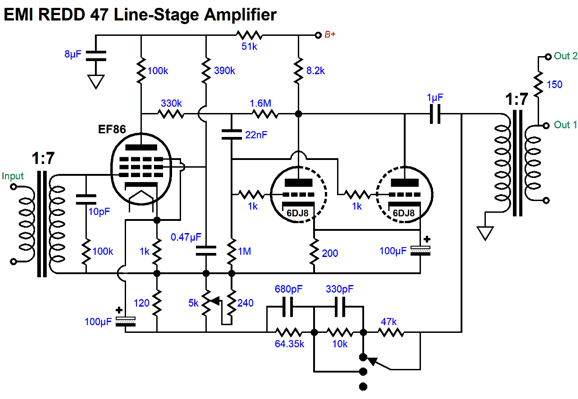
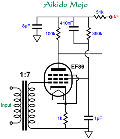
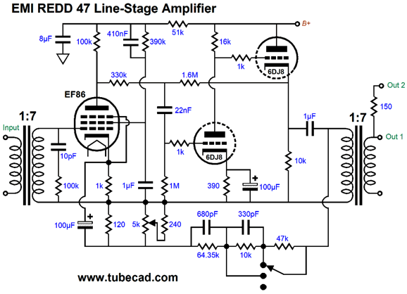
The input signal transformer the signal voltage steps-up the signal by 1:7, which the EF86 then further amplifies before passing the signal to the anode-follower gain formed by the two 6DJ8/E88CC triodes in parallel. A local negative feedback loop spans from the EF86's plate to the two combined 6DJ8 plates. In addition, a global negative feedback loop extends from the two joined 6DJ8 plates to the EF86's cathode. Moreover, a three-position switch allows the global feedback loop establish three gain settings (34, 40 or 46 dB), and small gain adjustments were accomplished by a potentiometer located at the EF86's cathode circuit. The output signal then enters an output signal transformer, which steps-down the signal by 7:1. The power supply used shunt voltage regulator obtained by two 0A2 voltage-reference tubes in series, creating a fairly stable 300V B+ voltage. All in all, an interesting design. I happen to like the EF86 and I own a few NOS units. The use of the anode-follower (aka plate-follower) is interesting, as is the tweaking of the gain through the potentiometer at the EF86 cathode. I also favor the designer's choice to keep the global negative feedback loop inside the scope of the two tubes, rather than extending to the other side of the output transformer. What would I change? Many would argue that nothing needs changing, as the stock REDD 47 was a close perfect as anyone could get. Maybe. Maybe not. It has reputation for being punchy and, when overdriven, wonderfully rich sounding. Think harmonic restoration. One minor modification would be to add some Aikido mojo to the pentode input stage.
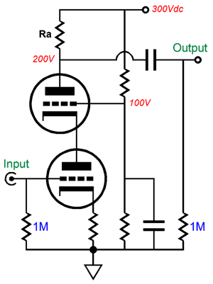
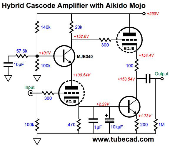
Shunting the grid-2 390k resistor with the 410nF capacitor and using a 1µF to ground rather than the stock 0.47µF capacitor results in a vastly improved PSRR: about 150 times less ripple at the pentode's plate. By the way, the EF86 only yields a gain of 80 (+38dB). In contrast, a 6DJ8-based cascode can deliver a gain over 100, with a bypassed cathode resistor. Here is an example of the cascode topology:
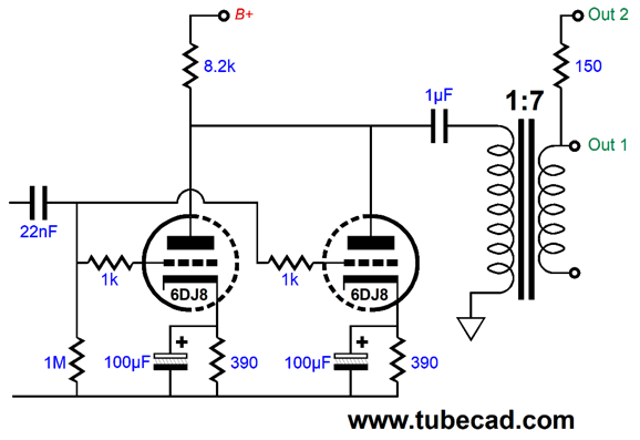
What about the two-triode anode follower? Is it perfect? No. If nothing else, we could give each triode its own cathode resistor, with its own bypass capacitor. This way the two triodes can find their bias points.
As I looked at the output transformer, I wondered if the anode-follower stage was up to the task. What task? The transformer's winding ratio is 7:1, which means that is impedance ratio is equal 7²:1 or 49:1. Thus, a 200-ohm external load impedance will be reflected to the 6DJ8 plate as 9800 ohms. Thus, the 8.2k plate resistor is effectively in parallel with 9.8k, making a parallel amount of 4464 ohms. What if we hotrod the anode-follower stage?
The cathode follower output stage now drives the two negative feedback loops and the output transformer primary impedance, while the grounded-cathode amplifier input stage is relatively unloaded in this arrangement. On the other hand, I haven't actually run any SPICE simulations on the this complete rework of the design. I once have encountered that adding a cathode follower to a previously working amplifier ended up making it unstable, once the negative feedback loop was attached; but with the negative feedback loop open, the performance did improve the performance, at least in terms of high-frequency response. This might be the outcome here. Another possible arrangement would be to add push-pull buffer at the output, say a White cathode follower or a SRCFPP. Just looking at the low 200-ohm input impedance and the high output impedance of this line-stage amplifier makes me wonder if an entirely redesigned version wouldn't prove better. For example, the fine volume adjustment performed by the potentiometer at the cathode seems sub-optimal. In addition, is one big global negative-feedback loop the best way to go? Still, it was fun looking at the old design. I was going to include the following section in this previous section, but I feared it would just confuse things for many.
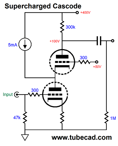
Crazy-Gain Cascode One workaround is a seldom seen version of the cascode. I have shown this variation a few times here; the last time being a year ago in post 488, wherein I labeled the circuit the "Supercharged Cascode."
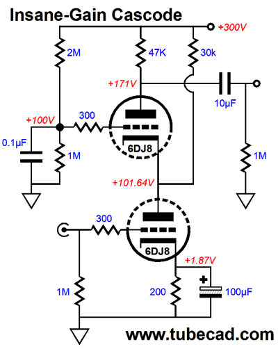
We can replace the constant-current source with a large-valued resistor, with only a slight decrease in performance.
The bottom triode sees a current flow of 9.36mA, while the top triode sees only 2.74mA, whereas the 30k resistor sees a flow of 6.62mA. The higher current flow through the bottom triode ensures great transconductance and lower noise from the bottom triode. In order to get away with an idle current flow of 9.36mA through a 47k plate resistor would require a B+ voltage over 600Vdc. In other words, the setup allows to get the same high at a lower B+ voltage. Speaking of gain, how much do we realize with this circuit? This cascode delivers 275 or 48.8dB, an 11dB improvement over the EF86 pentode circuit. In addition, the added cathode follower in my remake unloads the anode-follower stage, so more gain would develop compared to the stack circuit. The combination of these two gain enhancements could get us closer to 60dB of gain, as the open-loop gain would top over 70dB, leaving 10dB for feedback overhead. Okay, what's not to like here? Positive PSRR, not negative PSRR. It's bad enough to have no power-supply noise rejection ratio, but positive amplification of the B+ voltage noise is far worse. Well, you didn't think that I wouldn't strive to fix this problem, did you?
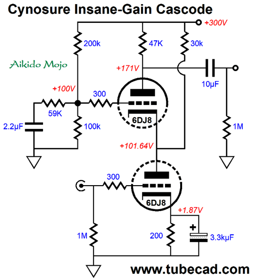
The Aikido mojo is found in the extra 59k resistor. I call it a cynosure resistor, as it reminds me of a dog's wagging tail, his best feature. This added resistor leaves the DC voltage division in place, but modifies the AC signal division. In this case, the signal is the B+ voltage ripple. The result is that a portion of the power-supply noise injects into the top triode's grid. The result is a huge enhancement in PSRR.
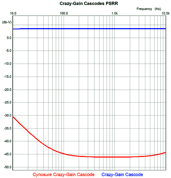
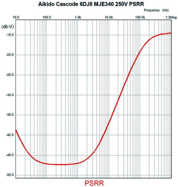
Note the attenuation at 120Hz, the ripple frequency in countries with 60Hz wall voltage; here we see a -48dB improvement. Not bad. By the way, we can apply this Crazy-Gain technique to a hybrid version that uses just one 6DJ8. Here is the hybrid cascode, but wit out the huge gain increase.
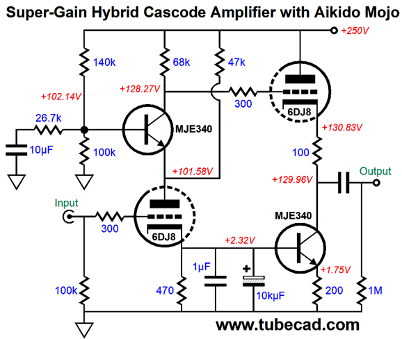
This is actually a two-stage circuit, with a cascode first stage and a cathode-follower output stage. Okay, let's boost the gain.
How high is the gain? Over 400 for the above circuit in SPICE simulation. In addition, the PSRR is fine.
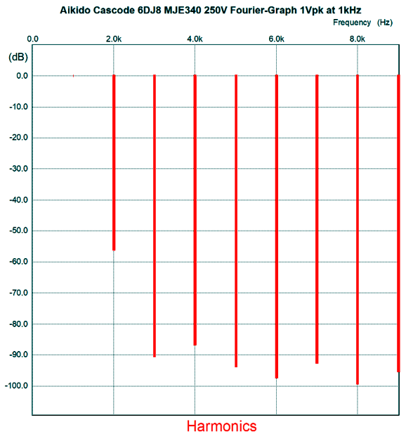
In terms of distortion, this circuit does well. Here is the Fourier graph.
We see mostly 2nd harmonic content.
Music Recommendation: Not Music
//JRB
User Guides for GlassWare Software
For those of you who still have old computers running Windows XP (32-bit) or any other Windows 32-bit OS, I have setup the download availability of my old old standards: Tube CAD, SE Amp CAD, and Audio Gadgets. The downloads are at the GlassWare-Yahoo store and the price is only $9.95 for each program. http://glass-ware.stores.yahoo.net/adsoffromgla.html So many have asked that I had to do it. WARNING: THESE THREE PROGRAMS WILL NOT RUN UNDER VISTA 64-Bit or WINDOWS 7 & 8 or any other 64-bit OS. I do plan on remaking all of these programs into 64-bit versions, but it will be a huge ordeal, as programming requires vast chunks of noise-free time, something very rare with children running about. Ideally, I would love to come out with versions that run on iPads and Android-OS tablets.
//JRB
|
|
I know that some readers wish to avoid Patreon, so here is a PayPal button instead. Thanks. John Broskie Special Thanks to King Heiple John Gives
Special Thanks to the Special 83
I am truly stunned and appreciative of their support. In addition I want to thank the following patrons:
All of your support makes a big difference. I would love to arrive at the point where creating my posts was my top priority of the day, not something that I have to steal time from other obligations to do. The more support I get, the higher up these posts move up in deserving attention. If you have been reading my posts, you know that my lifetime goal is reaching post number one thousand. I have 497 more to go. My second goal was to gather 1,000 patrons. Well, that no longer seems possible to me, so I will shoot for a mighty 100 instead. Thus, I have 17 patrons to go. Help me get there.
Only $12.95 TCJ My-Stock DB
Version 2 Improvements *User definable Download for www.glass-ware.com |
||
| www.tubecad.com Copyright © 1999-2020 GlassWare All Rights Reserved |

