| John Broskie's Guide to Tube Circuit Analysis & Design |
|
01 September 2020 Post 512
Forward to 1938
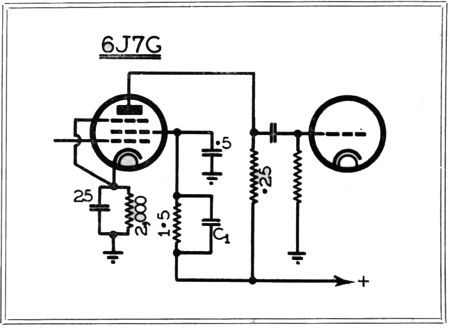
A pentode's grid-2 receives an inject of some of the power-supply, which then forces a noise null at the plate.
Here is the text:
Wow! Ripple galore, all 10V of it. In 1938, capacitors were not cheap, nor were resistors and tubes (i.e. valves). Capacitors over 100µF and 450V were the stuff of dreams.
Two-Stage Tube Amplifiers
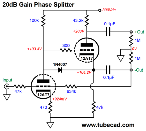
As we are not limited to unity gain, we alter the negative feedback loop resistors to develop gain. Indeed, setting a gain of 20dB (1:10) is easily achievable with common audio small-signal tubes, such as the 12AT7/ECC81 or 12AY7 or 12AX7/ECC83. With a gain of 20dB, 1Vpk of unbalanced input signal would become +/-10Vpk of balanced outputs, or +/-20Vpk of differential signal.
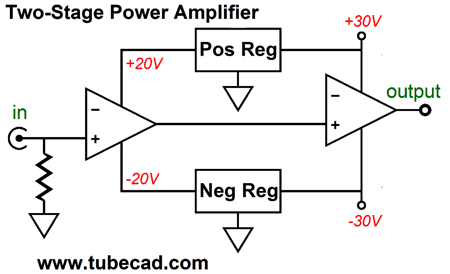
The negative-feedback phase splitter, however, finds a wider application than just tube-based equalizers. For example, we can use this circuit as the first stage of a two-stage power amplifier, with each stage holding its own negative-feedback loop; of course, second stage would be push-pull power amplifier, which could the form of a circlotron output stage or the more conventional push-pull transformer-coupled version. Two-stage power amplifiers have made many appearances here before, but are probably nonexistent elsewhere. Why? Theoretically, one global negative feedback loop will always result in less distortion than two separate negative feedback loops in series. Like so many theoretical conclusions, however, the underlining assumption is of a best-case scenario. What is the best-case scenario for an audio power amplifier? Answer: a sinewave generator providing a single-frequency, fixed-amplitude input signal and an 8-ohm resistor as the load. In contrast, reality gives us music made up of a multitude of frequencies and dynamically varying amplitudes and reactive electromechanical loads know as loudspeakers. Reality is messy. For example, excepting systems consisting of horn loudspeakers and 200W amplifiers, all power amplifiers clip. Some do so gracefully, others not so gracefully. In a well-designed two negative-feedback-staged power amplifier, only the second, the output, amplifier will clip. Since the first, the input, amplifier didn't clip, it doesn't have to recover.
(See post 446 for more explication of two-amplifier cascades.) In addition, since the first amplifier's output voltage swing is smaller than that of the second amplifier, we can apply voltage regulation to the first amplifier's power-supply rails.
The assumption here was that two solid-state amplifiers are used. Tube-based amplifiers are radically different, as the output tubes are seldom, if ever, run in cathode follower mode, unlike transistors and MOSFETs which are usually run in emitter-follower and source-follower mode. Because these solid-state output devices do not deliver any signal gain, the driver stage must supply a voltage swing larger than the output swing. With tube amplifiers, on the other hand, the output tubes develop signal gain, which means that the output tube's input signal is small relative to its plate voltage swings; thus, adding regulation to the first half of the amplifier is no big deal, as we do not require huge voltage swings from the input and driver stages. One issue specific to tube-based power amplifiers is that inter-stage coupling capacitors and signal transformers introduce phase shifts, which makes adding a negative feedback loop more difficult, as we never want the feedback to go from being negative to being positive. Of course, the fewer coupling capacitors the better, something the composite power amplifier made up of two sub amplifiers, each with its own negative feedback loop, makes easier to realize. For example, we could base the second amplifier on the following topology.
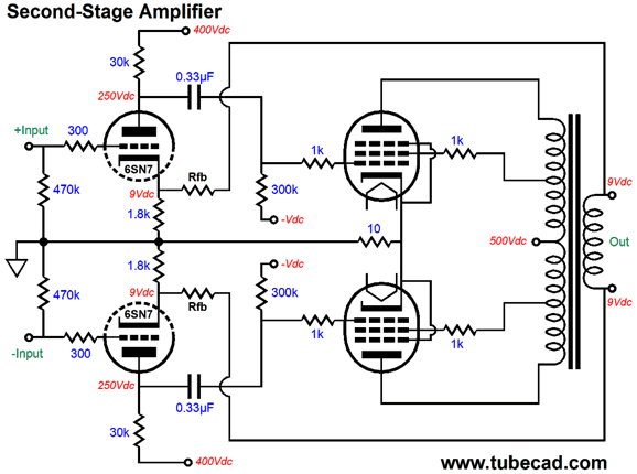
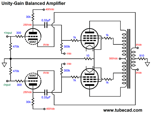
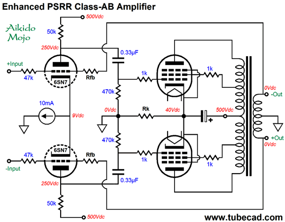
The assumption here is that the balanced input signal would be a hot +/-10Vpk from the first stage amplifier, whose input signal would be 1Vpk unbalanced. Each 6SN7 triode sees a negative feedback loop at its cathode. The feedback resistors (Rfb) set the gain. For example, say the maximum output power is 100W, which implies peak voltage swings of 40V for an 8-ohm load, the gain would be set to 1:2 or +6dB. The balanced input signal of +/-10Vpk becomes +/-Vpk at each secondary terminal, making a differential of +/-40Vpk. Note that the amplifier's output is not grounded and that both output terminals present 9Vdc. In other words, the output transformer's secondary is floating. If the secondary offers a center-tap, then we could ground the center-tap and alter the 6SN7 cathode resistor values, as the negative feedback resistor (Rfb) would effectively be in parallel with the cathode resistor. For example, say the negative feedback resistor were 2700 ohms, which would imply a gain of 2.5. With the secondary's center-tap grounded, we could replace the 1.8k cathode resistor with a 3k resistor and the negative feedback resistor with a 4.5k resistor, which in parallel equals 1.8k and still preserves the gain of 2.5. The 6SN7 in a grounded-cathode amplifier configuration with a plate resistor of 30k and a 1.8k unbypassed cathode resistor yields a gain of 7.5 (a gain of 15 with a bypassed cathode resistor). This amount of gain against the 10Vpk of input signal results output voltage swings of 75Vpk. Let's assume that the output tubes require an input signal of 37.5Vpk to develop full output power. Thus, a negative feedback ratio of 6dB would be needed so that the 10Vpk of input signal brings the amplifier to full output. Now, 6dB of negative feedback is not a lot. If more feedback is desired, we need to use a higher-mu triode, for example, the 6SL7 or 12SL7. The problem with this triode is that its high plate resistance will limit the high-frequency response of the output tubes. One workaround is to drive the output tube grids with a DC coupled cathode follower.
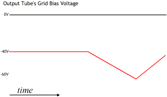
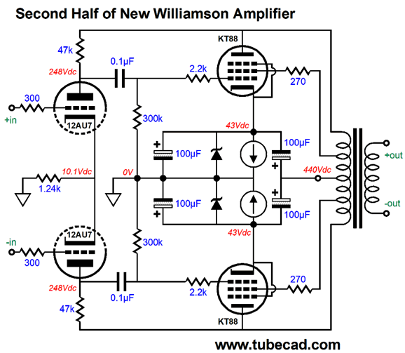
Click on schematic to see enlargement The 6SN7-based cathode followers prevent blocking distortion, wherein coupling capacitors become overly charged when the output tubes are driven into positive-grid current flow. With the DC coupling, there's no coupling capacitor. If the output tube draws grid current, the cathode follower delivers it. In contrast, with a coupling capacitor, the grid current charges up the capacitor to a higher value, which then slowly discharges. This results in the grid-bias voltage dropping too low, sometimes low enough to shut off the output tube's conduction altogether, hence blocking any output signal.
By the way, note that bottom cathode followers share a single plate resistor and decoupling capacitor. Also note the two plate-stopper resistors. Sadly, too few tube fanciers know about them. Much like grid-stopper resistors, they stop oscillations. Also note the low value for the ultra-linear resistors. Usually, these resistors are closer to 1k to 10k in value. Yet, the famous Dynaco ST-70 didn't use any ultra-linear resistors; in fact, I am sure that none of their tube-based power amplifiers used them, including their Mark IV, but it did use plate-stopper resistors. The Carver Silver 11 and Marantz 2 and 8B and 9 used 100 ohms; the Citation II amplifier, 270-ohm resistors; the Fisher amplifiers, 68 ohms; and the McIntosh 275, 220 ohms. In contrast, the Jadis JA-80 uses 2.7k ultra-linear resistors. That's quite a range, from zero to 2.7k. Why the big difference? The lower resistance values allow the ultra-linear taps to draw more current, which means that the screen grids are contributing to the output power. The original Genalex KT88 specified a maximum plate dissipation of 42W and a screen limit of 8W, with a combined total of 46W. Resistor values above 1k limit the current flow, so the ultra-linear configuration serves only to modify the plate current flow. While on the topic of stopper resistors, I should point out that many tube-based power amplifiers from the glory days of tube audio held anti-oscillation RC snubber networks across the two primary leads or across ultra-linear taps to primary taps.
The big problem with the conventional, transformer-coupled, push-pull, tube-based output stage is that most are run in class-AB. When one output tube ceases to conduct, its plate no longer loads its connection to the primary. Not good, as this unloaded half of the primary is free to oscillate. In contrast, the RC snubber continues to give the flapping primary lead something to bite on at high frequencies. If the primary does not offer any ultra-linear taps, we do the following.
In contrast, a push-pull output stage that runs in strict class-A sidesteps this problem, as neither output tube ever ceases to conduct. The added resistors are high in value, while the capacitors are low in value. Let's examine the grid-stopper resistors used on the output tubes. I have seen values that range from zero, i.e. no resistor, to 47k, with 10k being a common value. The 10k resistor's job isn't to quell parasitic oscillations, but to limit blocking distortion, as the high resistance serves an intrinsic current limit. Under normal operation, the grid draw no current; being far more negatively charged than the cathode and electrons only flowing from negative to positive, the grid cannot draw current. But with an explosive drum roll, the grid's voltage momentarily rises above the grid's voltage, the grid and cathode defining a forward biased diode, the grid conducts current. But with a 10k resistor in series with it and the coupling capacitor, the current flow is greatly limited. For example, if the grid went from drawing zero milliamperes to 10 milliamperes, the voltage drop across the 10k resistor would equal 100 volts, which would force the grid voltage far below the cathode voltage. In other words, this setup is self-limiting. The advantage the DC-coupled cathode follower offers over the high-valued grid-stopper resistor is that we can still use a low-valued grid-stopper resistor, preferably a non-inductive type, such as carbon-composition or bulk-foil, which allows greater high-frequency bandwidth. True, in a pentode-based output stage this is less of an issue, but in a triode-based output stage it can be decisive.
Partial Feedback Topology
In addition, Meno van der Veen wrote a book on the topic, Trans Tube Amplifiers, which is now available as a PDF.
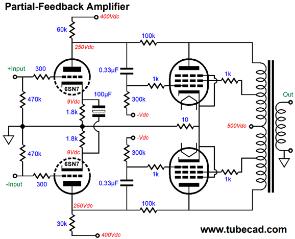
The following amplifier makes use of partial feedback.
In this setup, the output tubes are effectively configured as current-to-voltage converters, while the input stage is configured as a voltage-to-current converter.
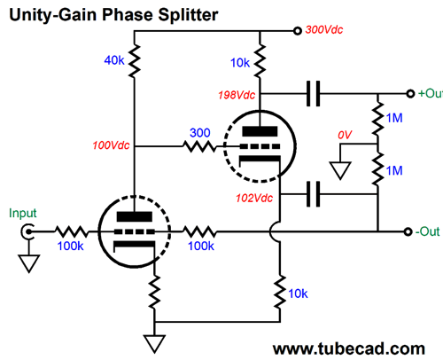
Unity-Gain Output Stage
The output transformer's 4-ohm output tap is grounded and output is taken from its 0 and 16-ohm taps. Placing an 8-ohm load across the 0 and 16-ohm taps results in halving the reflected impedance to the output tubes. For example, if the transformer nominal plate-to-plate impedance was 5k, it will now be 2.5k. This is not a problem, if we take the halved impedance into our calculations. What if you buy 4-ohm loudspeakers. No problem, just attach them from the 0 and 8-ohm taps. Note how each 6SN7's cathode resistor terminates into the output transformer's secondary. Thus, the negative feedback signal is not attenuated. The 1.8k cathode resistors will limit the 6SN7's potential gain, however. To increase the gain, hence the negative feedback, we could bypass each 1.8 cathode resistor with a large-valued capacitor. Another approach is to use a common cathode resistor.
This arrangement doubles the gain from the input triode, thereby doubling the amount of negative feedback. Do note that the outputs are now positively charged to 9Vdc. A third way to establish negative feedback is the following.
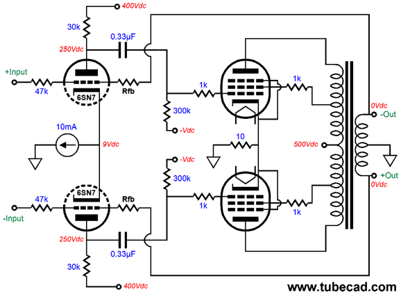
This is a modified version of the classic inverting amplifier. The constant-current source ensures higher gain from the 6SN7 triodes, and changing the value of the negative feedback resistors (Rfb) does not upset the 6SN7's idle current flow. By the way, our assumption here is that the output transformer's secondary holds a center-tap. What if it doesn't?
In the day of old, when tubes glowed bold, and transistors were not invented, just about all output transformers held 4-, 8-, and 16-ohm taps. Today, few loudspeaker present an impedance of 16-ohms; thus, the move is to only offering 4- and 8-ohm taps. Alas, the 4-ohm tap on such a secondary does not fall at the 50% position on the secondary, which it would have with a 4-, 8-, and 16-ohms tapped secondary. Why not? The square root of 16 is 4, so the 4-ohm tap has an equal number of turns of wire from it to the 0-tap as it does from 4-ohm tap to the 16-ohm tap; but the square root of 8 is 2.828, so if the secondary offered a 2.828-ohm tap, then that would be the center-tap of the secondary. In contrast, 4-ohm tap occurs at 70.7% of the winding on such a transformer.
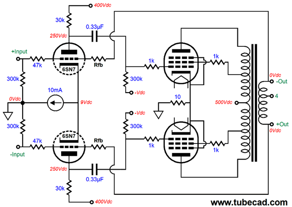
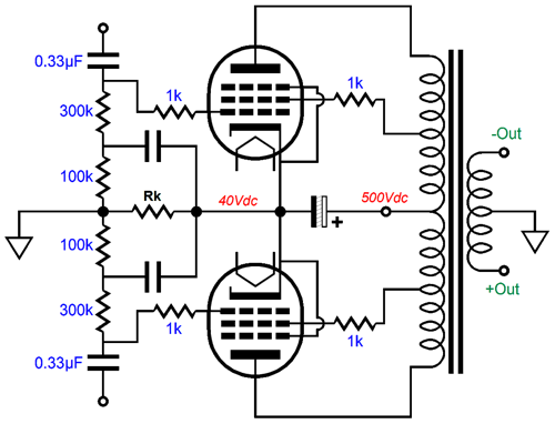
We can still use the 4- and 8-ohm secondary, but with just have to apply the connection to ground at the front of the amplifier.
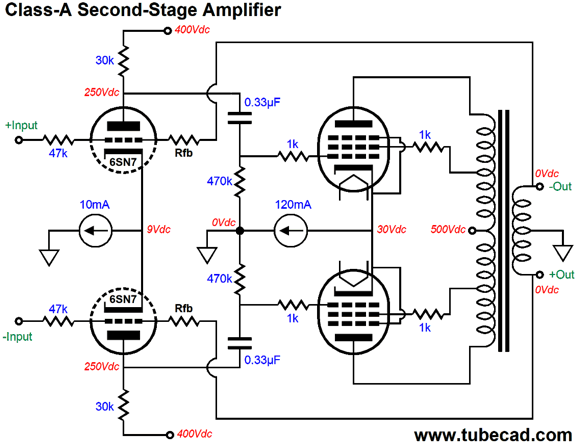
The two 300k grid resistors provide the path to ground. Both the 4- and 8-ohm taps are fully encompassed by the two negative feedback loops. At idle, both of the amplifier's outputs sit at ground potential. But with output signal, both outputs swing in anti-phase. In other words, this is a balanced output. If we are willing to live with the reduction of output power, we can use an additional constant-current source to auto-bias the output tubes.
Of course, the two output tubes must be matched. In addition, it would be wise to place the output tube heaters in series and power the string with a 12.6Vdc regulator. This way, should one output tube be missing from its socket or its heater element open, the other output tube will not draw twice as much current than it should. By the way, the PSRR is excellent with this setup, as neither output tube ever cuts off. (We could shunt the constant-current source with a 35V zener, which would allow to the output stage to break out of the class-A window of operation huge crescendos. During normal playback, the zener would never engage.) If the price of class-A is too high, we could still cathode-bias the output stage with a shared cathode resistor. The clever move would be not to terminate the shunting capacitor to ground, but to the B+ voltage connection. In addition, we must not use an RC filter for the input stage, as we must directly connect it to the output stage's B+ voltage.
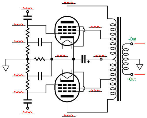
The logic behind this move is that constant-current source ensures that the input stage exhibits zero PSRR, so all the power-supply noise will appear at the balanced output. The output stage's shunting capacitor relays the power-supply noise to the two cathodes. Thus, the output tube grids, cathodes, screens, and plate will see all the power-supply noise, which means that the power-supply noise falls out of the equation. Imagine you are seating in an airplane traveling at 400mph. Your body, your cup of coffee, your book, your seat—all travel at the speed. If any of these items traveled at 380mph, you would be in trouble. As long as all of travels at the same speed, the speed doesn't count, as you be stationary or moving at mach two. In much the same way, if everything that attaches to the output tubes is equally contaminated with noise, the noise doesn't count, as the output tubes cannot see any of it. The one weakness in this circuit is the 470k grid resistors, as they will shunt away a small portion of the power-supply noise, when we desire 100% of the noise. Here is a workaround.
The added capacitors and resistors couple the grid resistors to the power-supply noise.
Once again, as the amplifier's output stage cannot see the power-supply noise, it does not appear at the output.
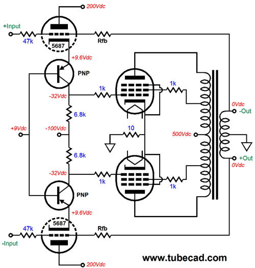
A Hybrid Variation
The idle current flow through each 5687 triode is 10mA. This form of cascode realizes a great deal of gain, as the triode's transconductance is maintained, so the resulting gain roughly equals gm against Rc. The 5687's gm at 10mA and a cathode-to-plate voltage of 190V is about 5mA/V, which against the 6.8k collector resistor equals 34. Assuming a balanced input signal of 10Vpk, the feedback ratio should be about 20dB.
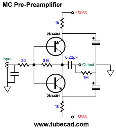
The Simple MC Pre-Preamplifier
I was hunting for a blank sheet of sketchpad and I found this circuit that I had drawn a few years ago, but forgot. Would it really work, I wondered. Well, SPICE said it does. The pre-preamp develops a gain of 1:10 or 20dB. The THD was vanishingly low, as in many zeros after the decimal point before we hit an integer. One problem, however, was a small DC offset at the input. Normally, it would not be that big a deal. With the hyper skinny wire in the moving-coil cartridge, however, even a small DC offset is a big pain. The obvious workaround is to add a DC servo.
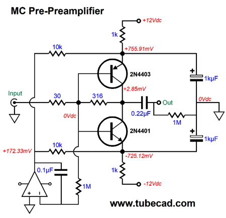
The OpAmp should hold a FET input stage and a low intrinsic DC offset. What about the 2.85mV at the output? If the pre-preamp feeds a tube phono stage, we can DC couple the output, saving us the hassle and cost of the output coupling capacitor. With a solid-state phono stage, we should leave the capacitor in place. By the way, this is an inverting amplifier. If the following phono stage also inverts, we need not bother; if it doesn't, then we can flip the leads on the cartridge. Okay, I couldn't resist the challenge of designing a single-transistor pre-preamplifier.
Each channel requires its own floating power supply, such as a battery.
Music Recommendation: The Astounding Eyes Of Rita I was once asked what my favorite ten albums were. Right near the top of the list was Anouar Brahem's album, The Astounding Eyes Of Rita. Imagine a jazzy, soulful music played with North African traditional instruments and rhythms. Anouar Brahem is a Tunisian oud player, composer, and world-jazz master. The album is dedicated to the late Palestinian poet Mahmoud Darwish. The "Rita" of Darwish's poems was a Jewish woman whom he loved when he was living in Haifa, according to Wikipedia; and as you listen to the track, The Astounding Eyes Of Rita, you feel his love for her. Amazing. In addition, the album, like most ECM albums, is demo grade.
//JRB
User Guides for GlassWare Software
For those of you who still have old computers running Windows XP (32-bit) or any other Windows 32-bit OS, I have setup the download availability of my old old standards: Tube CAD, SE Amp CAD, and Audio Gadgets. The downloads are at the GlassWare-Yahoo store and the price is only $9.95 for each program. http://glass-ware.stores.yahoo.net/adsoffromgla.html So many have asked that I had to do it. WARNING: THESE THREE PROGRAMS WILL NOT RUN UNDER VISTA 64-Bit or WINDOWS 7 & 8 & 10 or any other 64-bit OS. I do plan on remaking all of these programs into 64-bit versions, but it will be a huge ordeal, as programming requires vast chunks of noise-free time, something very rare with children running about. Ideally, I would love to come out with versions that run on iPads and Android-OS tablets.
//JRB
|
|
I know that some readers wish to avoid Patreon, so here is a PayPal button instead. Thanks. John Broskie
John Gives
Special Thanks to the Special 86
I am truly stunned and appreciative of their support. In addition I want to thank the following patrons:
All of your support makes a big difference. I would love to arrive at the point where creating my posts was my top priority of the day, not something that I have to steal time from other obligations to do. The more support I get, the higher up these posts move up in deserving attention. If you have been reading my posts, you know that my lifetime goal is reaching post number one thousand. I have 488 more to go. My second goal was to gather 1,000 patrons. Well, that no longer seems possible to me, so I will shoot for a mighty 100 instead. Thus, I have 14 patrons to go. Help me get there.
Only $12.95 TCJ My-Stock DB
Version 2 Improvements *User definable Download for www.glass-ware.com |
||


| www.tubecad.com Copyright © 1999-2020 GlassWare All Rights Reserved |