| John Broskie's Guide to Tube Circuit Analysis & Design |
21 December 2020 Post Number 523
SUPER Special THANKS to King Heiple! Not only am I stunned by his generosity, I continue to be stunned by it. Every reader should also say thanks to him. Thanks again, King. Mr. Heiple, you are so aptly named.
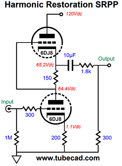
SRPP Harmonic Restoration Circuit
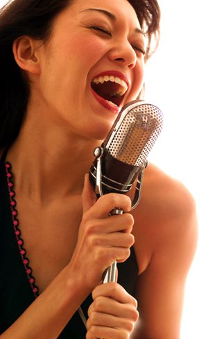
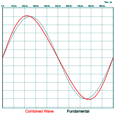
The photo above offers a visual analogy of thinned sonics, while the photo below displays the analogy of a riper sonic presentation.
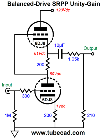
Perhaps both photos are off the mark, both departing from reality—but I know which one I prefer. The SRPP makes an odd choice for a harmonic restoration circuit, as it is fundamentally a push-pull amplifier that is load dependent. Furthermore, its distortion harmonics (when optimized for balanced output) betray a strong 3rd harmonic, the result of the push-pull action canceling the 2nd harmonic, not at all what we want. For example, here is a low-voltage SRPP optimized to drive a 1260-ohm load, which is tapped to deliver unity gain. Another way to put is that the load is optimized to the triodes and cathode resistors.
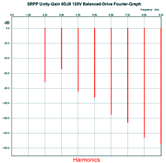
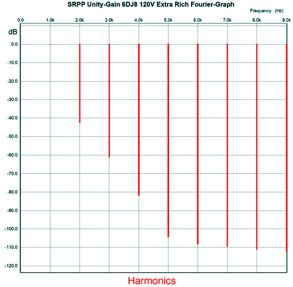
Both the top and bottom triode swing equal current swings into the load. Here is the SPICE-generated Fourier graph for 1Vpk at 1kHz. (The output at the top triode's cathode was 6Vpk.)
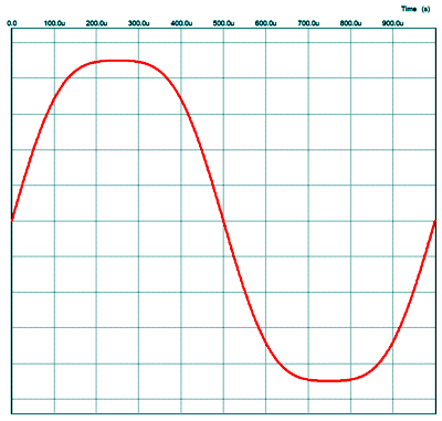
Considering the low impedance load, amazingly low distortion, save for the dang 3rd harmonic. I don't like 3rd harmonic distortion, calling its addition the cold hand of death. Here is what 3rd harmonic distortion looks like:
I added 10% of 3rd to the fundamental. Note how it looks compressed; well, that's how it sounds, dead, lifeless. Here is the same amount of 2nd harmonic distortion.
The addition of 2nd harmonic makes for a riper, more resonant sound. It sounds natural, as it is what we encounter in reality, as vibrating objects tend to give rise to a second harmonic. Even air imposes a second-harmonic distortion. Now, 10% is a lot distortion, but many cannot hear it—that is that they cannot her it when it only comprises the 2nd harmonic. On the other hand, 5th, 7th, 9th... harmonics set our teeth on edge. If we increase the 2nd harmonic over 20%, the resulting sound reminds me of grossly under-biased amplifiers. Okay, how do we use an SRPP circuit and get a lovely even cascade of harmonics? We ruin its balance.
Note the dissimilar cathode resistor values, 200 and 150 ohms. In addition, the 2100-ohm load impedance is too high. Thus, we have two breaks in balance. Here is the results.
While still a tad shy of 1%, the harmonics do cascade naturally and the 3rd is nicely suppressed. Okay, why would we need a low-voltage harmonic restoration circuit based on the SRPP? Two answers come to mind. The first is that this circuit's output impedance is a low 280 ohms, only due to the two-resistor voltage divider, not due to the SRPP, whose Zo is high, not low. The second is that it puts the SRPP 12Vac PCB to use. This SRPP design is powered by 12Vac wallwart or 12Vac transformer.
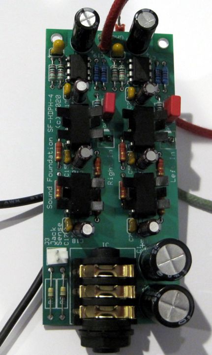
Why is the second answer deemed an advantage? I got an early Christmas present form a reader, James, who was kind enough to give me a small solid-state headphone amplifier he had designed, which was loosely based on a circuit from post 519:
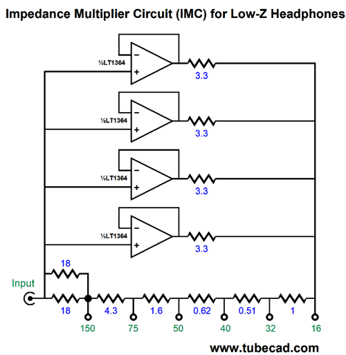
His circuit also uses four LT1364 amplifiers in parallel (two dual OpAmps per channel), each with a 3.3-ohm output resistor. Then, a high performance OpAmp (an LME49720) drives these four amplifiers and applies a global feedback loop over all of it, establishing a gain close to 10dB (1 : 2.96).
It runs off of a monopolar power supply between 12Vdc to 15Vdc, and the SRPP 12Vac PCB delivers 12.4Vdc (zener shunt regulated) to the two 6DJ8 heaters, which are wired in series. In other words, we get a free 12.4Vdc power supply of sorts. What would make this an interesting pairing is that solid-state half is about distortion-free as the current state of the art allows. James include a full printout of Audio Precision analysis. The THD is below 0.003%; the bandwidth ruler flat; the signal-to-noise ratio exemplary. So the pairing consists of a tube circuit made purposely extra ripe with a super clean solid-state headphone amplifier. Sounds super interesting, does it not? Now, all I need to do is find a nice enclosure. I bet you are in the same sticky situation of always being on the hunt for suitable metal boxes.
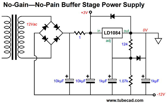
More No-Gain, No Pain
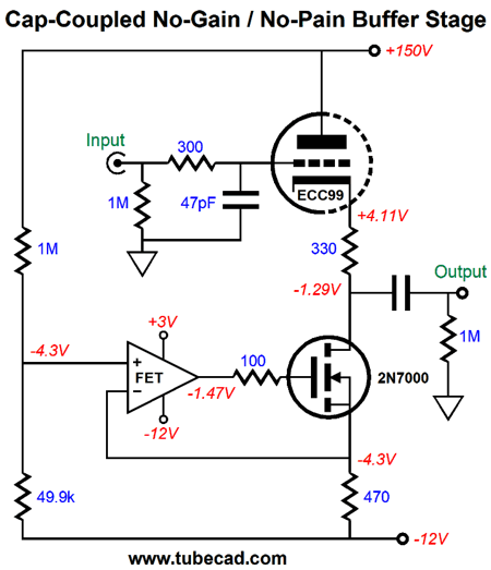
In fact, I am famous for having built naked single-ended output stages that passed the job of creating signal gain to the line-stage amplifier, as the amplifier held no input or driver stage, just a power supply and output tubes and output transformer. Nevertheless, these are exceptional situations. So, if we seldom need extra gain, why not build a passive line stage, which would hold little more than a selector switch and attenuator? Many do, including me several times, but I have always gone back to an active line-stage amplifier, as passive setups always failed to win my ears in the end, always sounding thinner, less substantial than active. Apparently, this being one of those examples where less is less and more is more. Theoretically, passive must be better, but reality is under no obligation to conform to theory—just the opposite. The intermediate position between passive and active-with-gain is active-without-gain; a buffer stage, in other words. The active buffer provides only current gain, no voltage gain. In post 520, we saw several variations on a cathode follower, most using a compliant-constant-current source and DC servo to eliminate the output coupling capacitor. If we are willing to live with a coupling capacitor, which is vastly safer, then we can lose the DC servo circuit. We should, however, hold on to the constant-current source. In post 520, I ended the section on no-gain buffers with this circuit:
The OpAmp controls the MOSFET's current conduction; in addition, the OpAmp superimposes an anti-phase ripple-induced current flow that forces a power-supply noise null at the output. I wondered how well the circuit would work without the OpAmp, leaving the MOSFET to work on its own.
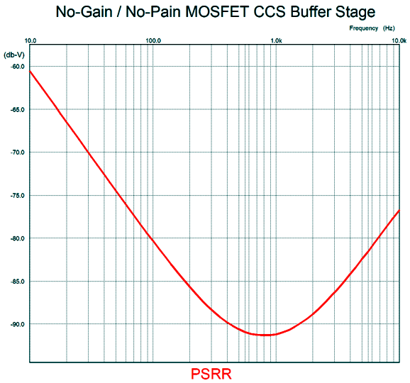
Note that the two-resistor voltage divider that bridges the B+ voltage to the -12Vdc power-supply rail is DC coupled throughout. At 1kHz, the PSRR null is deep, coming in at better than -90dB in SPICE simulations.
But at 100Hz, the null is only -80dB deep. I expected much more and deeper down. Possibly, a different MOSFET would improve the situation. I then tried replacing the MOSFET with a transistor.
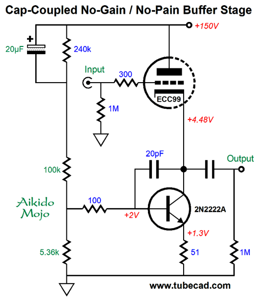
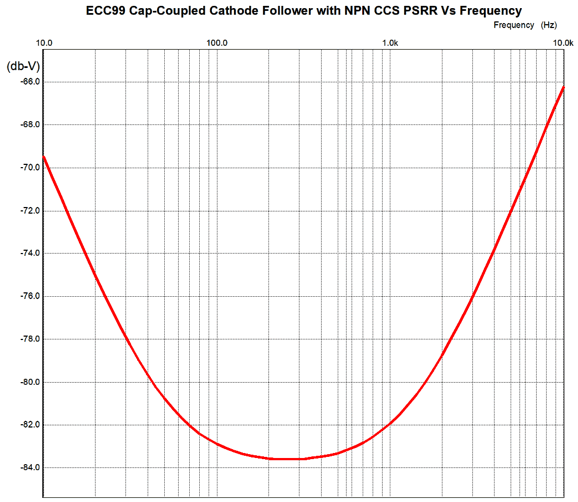
Note that absence of a negative power-supply rail. The 2N2222A NPN transistor needed the addition of the 100-ohm resistor and 20pF capacitor to prevent ultra-high frequency oscillation. In spite of the large 20µF capacitor, the PSRR null extended only down to 200Hz before rising towards DC. (A larger-valued capacitor would move the null lower down in frequency.)
Since big capacitors are a big pain, I wondered if using a Darlington configuration would not allow for smaller capacitor values.
After considerable tweaking, this arrangement made the deepest and most extended PSRR null.
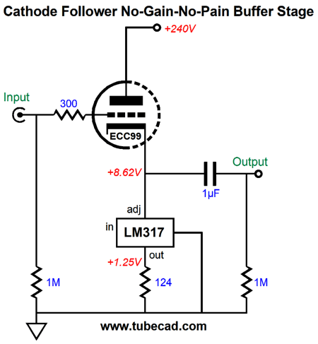
Note how the null extends down to 10Hz. (A decoupling capacitor shunting the B+ voltage to ground will take care of the rising slope towards high-frequencies.) Note the ratio between the two-resistor voltage divider resistors and the two shunting capacitors, as they hold to the inverse ratio in terms of value, but not in terms of impedance. I have to admit that I was surprised by how well this circuit worked. The next experiment was to use an LM317 in place of the transistors. The LM317 makes a fine constant-current source, and it comes in handy when we need more current flow than an LM334 can provide (10mA).
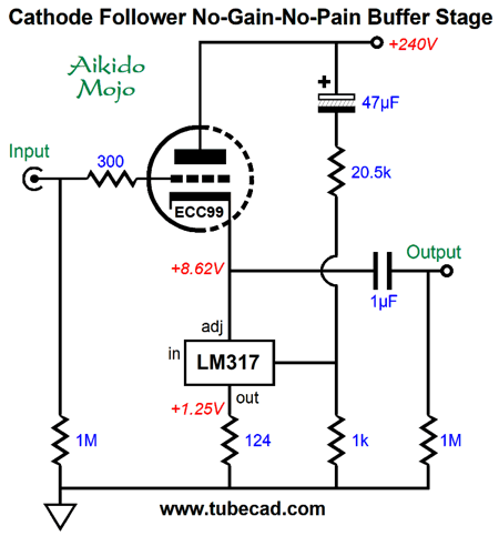
Note the B+ voltage of 240Vdc. I raised the B+ voltage to buy a higher cathode voltage from the ECC99. The LM317 is not an LDO (low-drop-out) regulator, and it requires at least 1.5V of headroom at 10mA, to which we must add its output voltage of 1.25V, bringing the total up to 2.75Vdc. In other words, the cathode follower's output voltage swing can only get to within 2.75V of the ground potential. As this circuit stands, no Aikido mojo obtains. In fact, a cathode follower loaded by a constant-current source at its cathode will leak 1/mu of the power-supply noise at its cathode. Adding some Aikido mojo requires adding a two-resistor voltage divider and extra capacitor.
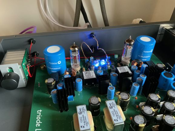
The LM317 sets an idle current flow of 10mA, as its output voltage (1.25V) divided by 124 equals (roughly) 10mA. Actually, the LM317's adjustment pin draws (worst-case) 100µA, which against the 1k-ohm resistor will bump up slightly the LM317's output voltage to 1.35V, so we can expect something closer to 10.8mA of idle current. With the added Aikido mojo, the PSRR falls from the Plain-Jane constant-current source's -30dB to -67dB. Not bad. Returning to the original No-Pain/No-Gain concept, reader and a Patreon patron, Dwight Warren, sent me some photos of his actual build of the circuit from post 102.
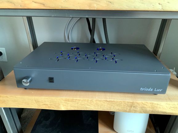
Note his skill! Wonderfully tidy. Also note that he included safety relays. What cannot be seen is that the PCB holds six layer and two ground planes. Dwight forwent B+ voltage regulator, preferring to use extensive filtering instead. Here it is on his equipment stand.
"Triode Luv" is an appropriate name for such a well-made project. Bravo!
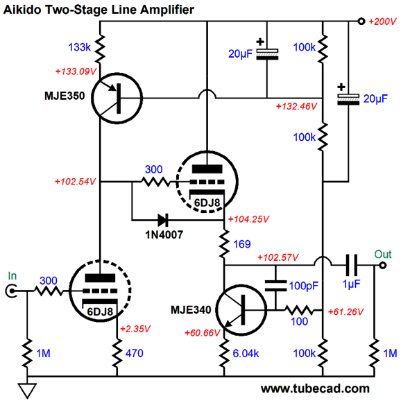
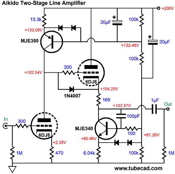
Line Amplifiers with Fancy Cathode Followers
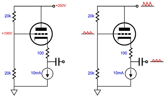
The input stage's triode and its plate resistor define a two-resistor voltage divider that halves the power-supply ripple at the plate. Here are the equivalent circuits, with DC voltages on the left and AC voltages on the right.
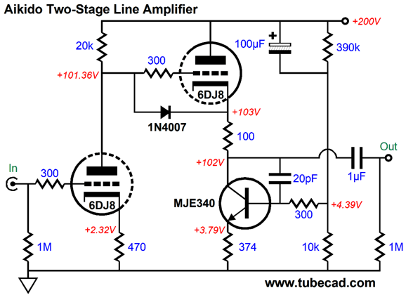
Okay, let's add some Aikido mojo.
The MJE340 PNP transistor sees 100% of the AC power-supply noise at its base, which it then relays to its emitter. The result is that as the B+ voltage bounces up, the transistor pulls down, forcing a power-supply-noise null at the output. When the B+ voltage bounces down, the transistor reduces its conduction, once again forcing a ripple null at the output. How did I find the correct value for the 374-ohm emitter resistor? I started with this formula: Re = (Rk + rp/(mu + 1))/0.5 Where Re is the emitter resistor value; Rk, the cathode resistor; rp, the triode's plate resistance; mu, the triode's amplification factor; and 0.5 is the amount of AC voltage division from the two-resistor voltage divider; in other words, 50%. My quick calculation gave me 384 ohms. SPICE disagreed and said that 374 would yield a deeper null. Who is right? I don't know, as 6DJ8 tubes differ. Nonetheless, something close to these two values will get near where we want to be. Getting near on the first try is important, as being off either makes you falsely conclude that a circuit won't work or compels you to go down a long path of value swapping. What if we replace the input stage's plate resistor with a constant-current source?
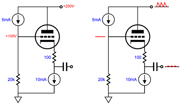
Well in theory, no power-supply noise will appear at the input triode's plate, as the constant-current source shields the plate from the ripple. This is good. The cathode follower, on the other hand, will leak 1/mu worth of ripple at its cathode. This is bad.
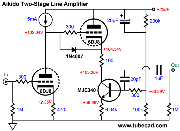
Undoing this much smaller amount of power-supply noise will require a far smaller amount of current variation form the constant-current source. How much less? We use the following formula: Re = Rp + Rk(mu + 1) My calculation gave me 6150 ohms; SPICE, 6040 ohms. Okay, what is the underlining logic behind the formula? We begin with the assumption that no power-supply noise leaks out the output, so the cathode follower's triode and its cathode resistor see 100% of the power-supply noise from the plate to the bottom of the cathode resistor. Next, we need to match the total impedance presented by the triode and its cathode resistor. The correct answer is not plate resistance plus the cathode resistor value, as the cathode resistor value gets effectively magnified by the triode. By how much? By the triode's mu + 1, so the 100-ohm resistor contributes 3200 ohms to the total, a total that the emitter resistor must match. Why? For a power-supply-noise null to obtain, the emitter resistor must see 100% of B+ voltage ripple across its leads, just as the triode and its cathode resistor does. It's easy enough in SPICE to plop a constant-current source into a circuit, but how would we actually build one for this circuit? Here is one possible setup.
The MJE350 PNP transistor, like the MJE340 NPN transistor, is rated for 300V. With an emitter resistor of 13.3k, its collector presents a huge impedance. Yet, about 1% of the power-supply noise got through. This leaked noise is tougher to eliminate than the same amount applied to the plate, as the grid sees it and relays it to its cathode. Workarounds include adding an additional PNP transistor to create cascoded constant-current source, but I sought something simpler. I increased the cathode follower's cathode resistor value until a deep power-supply-noise null. Note the value of 169 ohms, not 100 ohms. No doubt some are querying the need for a cathode resistor with a constant-current source load. Naked, unshielded cathodes can run into problems when driving capacitive loads; the small-valued cathode resistor decouples the cathode from the capacitance. After drawing a new circuit, I look for unseen potential problems. In this circuit, I worry about the NPN transistor. At startup, the two 20µF capacitors must be charged up and the triode will still be cold and not conducting, which means that this transistor's maximum emitter-to-base voltage (Veb) might be exceeded, as it is only 3V. We never want a transistor's Veb voltage to be surpassed, as the transistor might be destroyed; in fact, even if it isn't demolished, it becomes far noisier after experiencing such an over-voltage. The workaround is to add two protection diodes.
These added diodes limit the maximum emitter-to-base voltage to about 1.4V. Of course, different tubes will require different part values and operating voltages and currents. Obvious alternatives are the 6AQ8, 6H30, 6CG7, 6SN7, 12AU7, 12BH7, 12SX7, 5687, and ECC99. But the logic and formulas remain the same throughout.
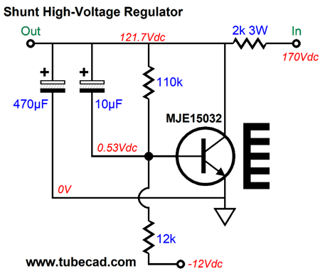
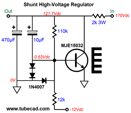
Solid-State Shunt Regulators
All voltage regulators require three key elements: a voltage reference, a pass device, and a negative feedback mechanism. In the circuit above, all three elements are evident. The raw 170Vdc enters at the right and regulated 150Vdc exits at the left. The high-voltage NPN transistor is configured as an inverting amplifier with the regulated -12Vdc acting as the signal source. The 110k and 12k resistors define both a two-resistor voltage divider and a set of negative feedback loop resistors. The 10µF capacitor shunts the 110k feedback resistor, which increases the high-frequency negative feedback. What's missing is some protection for the transistor.
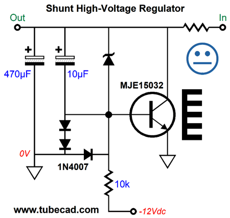
The three diodes offer protection to the transistor's base, limiting the maximum positive and negative voltage the base can see to +1.4V and -0.7V respectively. The huge 470µF shunts the output and works as the capacitor in the RC filter formed by it and the 2k series resistor. All in all, a fine high-voltage regulator this is, as any perturbation at the B+ voltage is relayed to the transistor's base, which forces a countervailing change in the transistor's current conduction to oppose the voltage fluctuation. An alternative setup replaces the 110k negative feedback resistor with a 150V zener, which results in tighter DC voltage regulation, but worse AC regulation, as zeners are intrinsically noisy. In fact, when making a noise source, zeners are often employed as noise generators. True, the 10µF helps, but not that much.
In short, I don't recommend this variation. A variation that is worth examining is a diamond configuration.
The 2N4403 PNP transistor is setup as an emitter follower, which allows us to use higher resistor values in the two-resistor voltage divider and a smaller and higher-quality shunting capacitor, 1µF of film versus 10µF of electrolytic. In fact, we might try shunting the 100k emitter resistor with a small film capacitor, say a 10nF polypropylene capacitor. From two transistors, the next logical step would be to use an OpAmp to drive the high-voltage transistor.
A rail-to-rail OpAmp is needed, such as the LME49721, as the transistor's base is above ground voltage and the OpAmp's positive rail voltage is only 3Vdc. Speaking of the OpAmp's positive rail voltage, where did it come from, as the bipolar power supply only holds two voltages? The answer is that a positive voltage regulator is used to create the regulated negative power-supply rail voltage of -12Vdc.
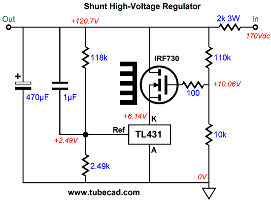
In general, positive voltage regulators outperform negative regulators and the raw DC input voltage to the positive regulator is greater than 0V by a few volts, which becomes a free low-voltage power-supply rail for powering the OpAmp. What if no negative power-supply rail voltage is available? We might use an IC shunt regulator, the LM431 and TL431.
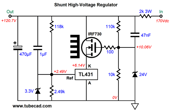
The IC shunt regulator can pass up to 100mA, but is voltage limited to 36V from anode to cathode. Of course, a tube-based circuit will require far more than 36V. Thus, the high-voltage MOSFET is added to the circuit and forms a cascode of sorts with the TL431. The two-resistor voltage divider sends a portion of the DC output voltage to the regulator's adjustment pin, along with 100% of the AC signal at the B+ voltage due to the shunting 1µF capacitor. The regulator's internal voltage reference is set to 2.5V, so the regulator will vary its current conduction until its adjustment pin sees 2.5Vdc. Wait's missing is protection zeners.
The two added zeners protect the TL431 at startup. The 3.3V zener protects the reference pin from over-voltages and from negative voltage when the power is shut off and the 1µF capacitor is still charged; the 24V zener, the cathode pin from seeing too high a voltage.
Music Recommendation:
Well, after reading Nabokov both praise and trash Russian writers and poets, and detail life in pre-Soviet Russian and the White Russian's exile from the Soviet Union, has put me in full Russophilia mood. I have always been a big fan of Russian classical music, from Mikhail Glinka to Alfred Schnittke. Thus, I searched through my collection of Russian composers, and I stopped at Yevgeny Sudbin's performance of Tchaikovsky's first Piano Concerto, paired with Nikolai Medtner's first Piano Concerto. (Amazon Music streaming service offers this album in 24-bit.) Tchaikovsky's concerto is a warhorse of the first order, whereas Medtner's, like so much of his compositions, is little known. Thus, the pairing was risky, but successful. Medtner, also a Russian composer, was a contemporary of Sergei Rachmaninoff and has become better known since his death in 1951, but not enough so. I must have heard at least ten recordings of Tchaikovsky's Piano Concerto No 1 , but this one holds a special charm due to Sudbin's art. My soul felt Russian after rehearing this album. Now, if only I liked vodka and cabbage soup. //JRB
*Paw of the Lion, La Griffe du Lion
User Guides for GlassWare Software
For those of you who still have old computers running Windows XP (32-bit) or any other Windows 32-bit OS, I have setup the download availability of my old old standards: Tube CAD, SE Amp CAD, and Audio Gadgets. The downloads are at the GlassWare-Yahoo store and the price is only $9.95 for each program. http://glass-ware.stores.yahoo.net/adsoffromgla.html So many have asked that I had to do it. WARNING: THESE THREE PROGRAMS WILL NOT RUN UNDER VISTA 64-Bit or WINDOWS 7, 8, and 10 if the OS is not 32-bit or if it is a 64-bit OS. I do plan on remaking all of these programs into 64-bit versions, but it will be a huge ordeal, as programming requires vast chunks of noise-free time, something very rare with children running about. Ideally, I would love to come out with versions that run on iPads and Android-OS tablets.
|
I know that some readers wish to avoid Patreon, so here is a PayPal button instead. Thanks. John Broskie
John Gives
Special Thanks to the Special 90 To all my patrons, all 90 of them, thank you all again. I want to especially thank
I am truly stunned and appreciative of their support. In addition I want to thank the following patrons:
All of your support makes a big difference. I would love to arrive at the point where creating my posts was my top priority of the day, not something that I have to steal time from other obligations to do. The more support I get, the higher up these posts move up in deserving attention.
If you have been reading my posts, you know that my lifetime goal is reaching post number one thousand. I have 477 more to go. My second goal was to gather 1,000 patrons. Well, that no longer seems possible to me, so I will shoot for a mighty 100 instead. Thus, I have 10 patrons to go. Help me get there.
Support the Tube CAD Journal & get an extremely powerful push-pull tube-amplifier simulator for TCJ Push-Pull Calculator
TCJ PPC Version 2 Improvements Rebuilt simulation engine *User definable
Download or CD ROM For more information, please visit our Web site : To purchase, please visit our Yahoo Store: |
|||


| www.tubecad.com Copyright © 1999-2020 GlassWare All Rights Reserved |