| John Broskie's Guide to Tube Circuit Analysis & Design |
|
12 January 2021 Post 525
Happy New Year!
2021 and Beyond
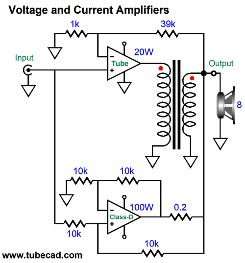
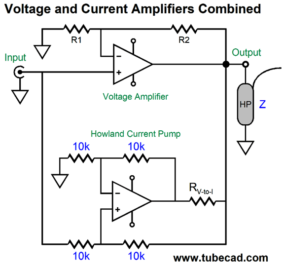
Hybrid HPA with Howland Current Pump I ended my last post on a bi-amped amplifier with the observation that electrodynamic planar loudspeakers and headphones, due to their ruler-flat impedance, would make the best fit with a hybrid amplifier that used a conventional voltage-out amplifier, either a tube-based or solid-state design, along with a solid-state Howland current pump circuit to provide most of the current delivery. In other words, the voltage-out amplifier would control the output signal, while the voltage-to-current amplifier blindly delivered needed current.
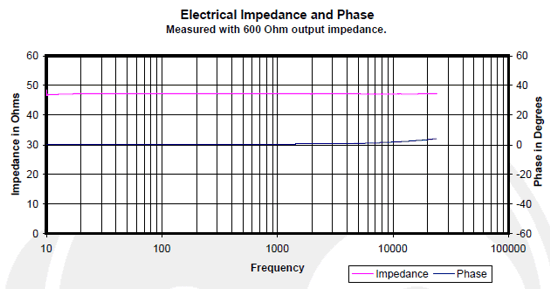
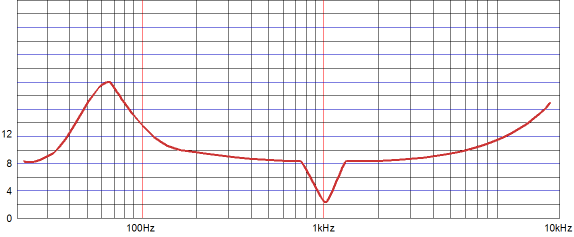
Well, the more I think about it, only the planar headphone is likely to deliver a ruler-flat impedance plotline. Why? Almost all loudspeakers hold crossovers; most headphones don't. For example, I looked up some of the Magnepan loudspeakers impedance plotlines, which I assumed would produce a flat impedance plot. Not flat. In fact, their plots looks as if they use a Linkwitz-Riley crossover alignment, as the impedance easily doubles at the crossover frequencies. True, my impedance flattening circuit for the LR crossover would help, but the loudspeakers do not come with it. (It could be added externally to the loudspeaker, however, which could make for a profitable accessory industry.) This leaves planar headphones, such as those made by Abyss, Audeze, Fostex, HiFiMAN, and others. (By the way, electrostatic headphones do not count, although they are also planar types, as they are effectively capacitive, not resistive, loads.)
Note the pink plot line. Very impressive, as even a straight length of wire presents some inductance.
Simply put, the idea is that we could build a tube-based headphone amplifier that both controls the output signal and co-drives the headphones, while the solid-state Howland current pump, a voltage-to-current circuit, delivers the bulk of the needed big current swings. If things worked out, the only time the tube-based headphone amplifier would deliver current into the headphones was when it was needed to correct the output signal.
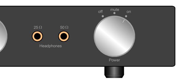
What would cause problems is a non-flat load impedance. If the impedance dips below the target impedance, the tube-based amplifier must make up the missing difference in needed current flow. If the impedance peaks, the voltage-out amplifier must sink the excess current from the Howland current pump. SPICE simulations of this hybrid headphone amplifier looked super promising, but one big problem remained. Because headphones are relatively cheap when compared to loudspeakers, even high-end cans, many own more than one pair, often with different load impedances. This is a problem, as this hybrid headphone amplifier must be designed with one designated fixed load impedance, as the Howland current pump circuit relentlessly dumps out a fixed voltage-to-current ratio of output current regardless of the load impedance, which leaves the tube-based headphone amplifier with task of correcting the mismatch between the target impedance and the actual impedance being driven. In other words, if a hybrid arrangement was designed to drive 32-ohm headphones, then 16-ohm and 300-ohm headphones shouldn't be driven. Thus, the remaining question is: Can we design this unique hybrid to accept multiple headphone load impedances? If just two headphone impedances presented themselves, say 25-ohms and 50-ohms, then I would simply opt for using two switching headphone jacks, one for each impedance. The Howland current pump circuit would hold two equal in value voltage-to-current resistors in series. When the 50-ohm headphones are plugged into their jack, both resistors are engaged. When the 25-ohm headphones are plugged in their jack, however, the jack's switching shorts out one resistor, so the Howland current pump delivers twice the current.
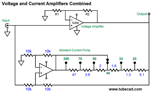
How do we select the right voltage-to-current resistor value? Easy enough, we take the headphone impedance and divide it by the tube-based headphone amplifier's gain. For example, if the gain came in at 1:5 (+14dB), we would divide the headphone's impedance of 50 ohms by 5 and get 10 ohms. In other words, when presented with an input signal of 1Vpk, the Howland current pump circuit will force out 1V/10-ohms of current, or 100mA peak, which against 50-ohm headphones equals 5Vpk of voltage swing, which matches the tube-based headphone amplifier gain with 1Vpk of input signal. What if we own three different headphones with three different impedances? I would then use a rotary switch with two poles and six positions, as it is easy to go from owning three headphones to owning four, so we might as well cover all the likely headphone impedances.
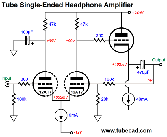
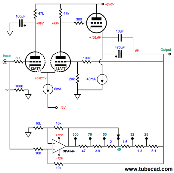
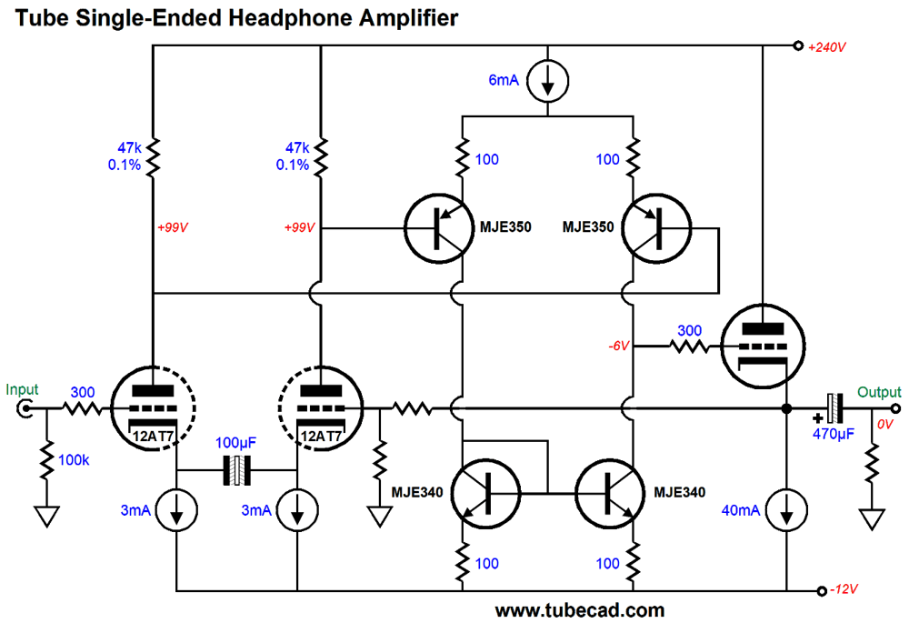
The headphone amplifier's negative feedback loop encompasses the Howland current pump's output, which fortunately presents an ultra-high impedance of over 15k. Thus, the headphone amplifier controls the output voltage that the headphones see. If it can—that is. If the headphone amplifier cannot deliver sufficient current to steer the output voltage, the Howland current pump will win or at least provoke much distortion. In other words, we must ensure that the tube-based headphone amplifier's output stage can put out more current than we would ever expect. Okay, let's look at a simple tube-based headphone amplifier circuit.
A cathode-coupled amplifier input stage feeds the cathode follower output stage its input signal, a signal that is not inverted relative to the input signal. The 100k and 20k resistors define a two-resistor voltage divider and feed the cathode-coupled amplifier's inverting input the negative feedback signal; and, thus, set the headphone amplifier's gain. If the tubes offered substantially more transconductance, the gain would come in at 1:6, as the gain formula for a non-inverting amplifier states that gain equals (R1 + R2)/R2 and (100k + 20K)/20k equals 6. The output stage, however, consists of a simple cathode follower with constant-current source loading. In other words, the headphone amplifier is a single-ended amplifier. With the 12AT7 input tube and two parallel ECC99 output triodes, SPICE simulations revealed that the gain is 1:5. By the way, we can get clever and use the "Broskie resistor" in place of the 100µF electrolytic capacitor, which superimposes the input signal on the input triode's plate, which neutralizes the input triode's grid-to-plate capacitance. See post 415 for more details.
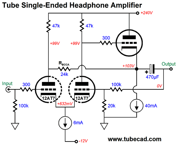
The only problem with this approach is that we must tweak resistor Rbcca's value with a any change in tube types or plate resistor values. In SPICE simulations, the 24k value worked extremely well in this circuit. Adding the Howland current pump is easy.
The power supply must hold three power-supply rail voltages, 240Vdc and +/-12Vdc. The tube heaters are powered by the bipolar power supply, as is the Howland current pump OpAmp. Speaking of which, the OPA544 is a small power amplifier IC with five pins and TO-220 mounting. It holds a FET input stage and can deliver 2A of peak current flow and is unity-gain stable. In addition, it works over a wide power supply range of ±10Vdc to ±35Vdc. It's only downside is that is not super quiet and fairly pricey at about $18 each.
No headphone yet devised by man requires 2A of peak current flow, but it doesn't hurt to have some reserves. At one RMAF I was told that a competent headphone amplifier had to be able to deliver 8Vpk with a 32-ohm load, which implies a peak current swing of 250mA. By the way, 8Vpk into an 8-ohm load equals 4W and equals 8W into a 4-ohm speaker, so we might be able to drive horn speakers or computer speakers with this hybrid amplifier. After running many SPICE simulations, I wondered if the tube half of the circuit wasn't holding the performance back, so I tested just the tube-based headphone amplifier and its performance into a low-impedance load wasn't all that great. Why not? Triodes are transconductance weak and present high internal impedances, neither work well with low-impedance loads. The size of the output tube is not the issue, transconductance is. For example, a 300B is a 40W power triode that offers a transconductance of only 4mA/V (with a cathode-to-plate voltage of 240V and an idle current flow of 40mA). In contrast, a 6DJ8 at 120V and 10mA offers close to 10mA/V of transconductance. Thus, four 6DJ8 triodes in parallel offer ten times as much transconductance than a single 300B.
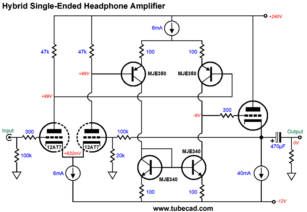
If we cannot squeeze more transconductance from the output tube, our only recourse is to get more gain from the input stage, as the increased gain will better fuel the negative feedback, resulting in effectively increasing the entire headphone amplifier's transconductance. In other words, the more open-loop gain the amplifier develops, the more output current we can force from the output tube. Swapping out the input tube, a 12AT7, with a 12AX7 only results in a modest increase in open-loop gain. We could cascode the differential input stage, a circuit sometimes called the Hedge circuit, which could develop much more gain, especially with a high-transconductance input tube, such as a 6DJ8. Well, since we are using a solid-state Howland current pump circuit, why not go hybrid within the tube-based headphone amplifier?
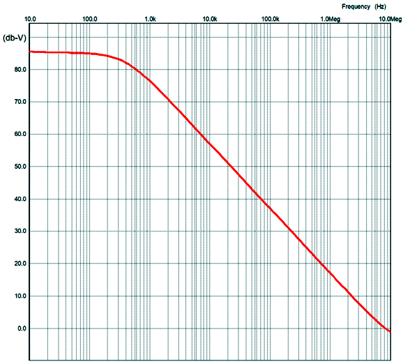
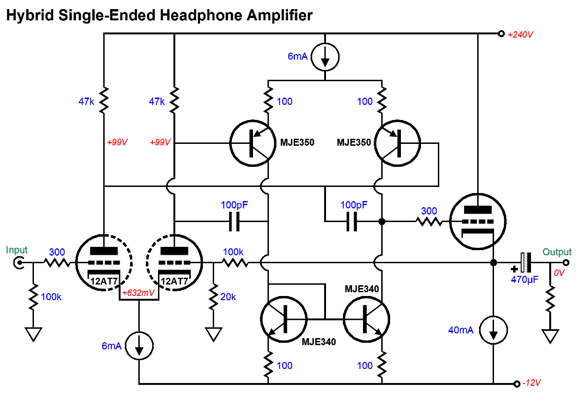
This circuit looks very 1980s, much like many OpAmps and MOSFET-based power amplifiers of the time. The tube-based input differential amplifier cascades into a PNP-transistor-based differential amplifier that is loaded by a current mirror. The result is a dramatic increase in gain; in this example, the open loop gain rises to almost 1:18,000 (85dB) in SPICE simulations. Here is a graph of the open-loop gain:
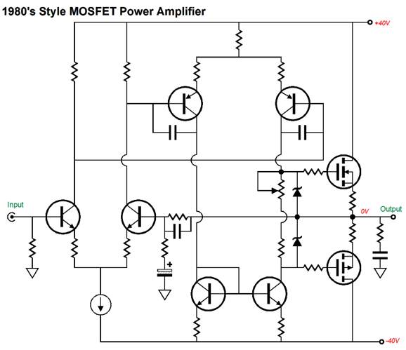
While still weak compared to an all solid-state design, this is a huge gain from a tube-based circuit is staggering. The two constant-current sources ensure a fine PSRR figure, coming in at -90dB at 100Hz in SPICE simulations. Only the top transistors, the two MJE350s, get hot, as only they see a huge voltage differential from emitter to collector. Speaking of 1980s style MOSFET power amplifiers, here is an example of that topology.
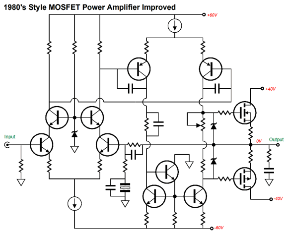
This amplifier worked well with the wonderful lateral MOSFETs being made at the time, but not so well with the VMOS (HEXFET) vertical types. Lateral MOSFETs are free from secondary breakdown and thermal runaway. In addition, they offer a consistent and lower turn-on voltage and far less input capacitance than the vertical types. Their big failing, however, is their relatively weak transconductance, easily only one tenth that of a comparable vertical MOSFET. As far as I am concerned, a negative temperature coefficient is worth a tenfold reduction in transconductance, as it makes the MOSFET inherently thermally stable. Sadly, today they are both rare and expensive (expensive for a solid-state device, dirt cheap compared to NOS tubes). By the way, my friends tell me that the new Exicon ECX10P20 and ECX10N20 lateral MOSFETs are actually better than the original Hitachi and Toshiba lateral MOSFETs. To make this 1980s MOSFET power amplifier work well with IRF240 and IRF9240 MOSFETs, we should run two sets of bipolar power supply voltages.
This amplifier enjoys a few additional tweaks, such as the cascoded input stage and the addition of a constant-current source in place of the PNP transistor differential amplifier's shared emitter resistor. Actually, what is needed is a NPN and PNP transistor class-AB driver stage, as the vertical MOSFET's input capacitance is oppressive, especially if we run many in parallel.
Okay back to the hybrid headphone amplifier circuit, as I looked over the schematic, I feared that it would prove spicy, i.e. that it would work flawlessly in SPICE simulations, but bomb in reality. Why? Unlike SPICE triodes, the two triodes in a real 12AT7/ECC81 tube are not perfectly matched—and the same holds true for all the resistor values. As I saw it, any imbalance in current flow from the input triodes would trash the PNP transistor differential amplifier. Thus, I sought workarounds.
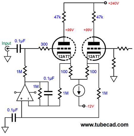
The idea here is that the input stage's two constant-current sources and non-polarized electrolytic capacitor would force equal voltage drops across the two plate resistors. Would they? They would if the constant-current sources and plate resistors were perfectly matched. My next idea was that I could use one constant-current source, if a DC servo loop circuit forced equal idle current flow through the two input triodes.
It's sneaky, but we run into resistor tolerances and the OpAmp's own DC offset voltage. I returned to SPICE and unbalanced the circuit, breaking the perfect resistor tolerance and triode matching. No problems. The circuit worked just as it had before. What went right? I guess that I have been dealing with negative-feedback-free circuits for so long that I forgot what a miracle negative feedback can be and why it was so universally adopted and appreciated. The two constant-current sources and high negative-feedback ratio compels balanced idle current flow from the triodes. In other words, I sought a workaround for a problem that didn't exist. A potential real problem is that the output triode's grid voltage might prove too low, which would limit the negative voltage swings, but not the positive swings. Remember, we are running a ±12Vdc bipolar power supply. The workaround, if we do not end up exceeding the output triode's dissipation limit, is to run a higher idle current. Another workaround would be to run a greater negative power-supply rail voltage, say -16Vdc, which could be the raw negative voltage entering a -12V voltage regulator. Another potential real problem is high-frequency instabilities, which SPICE did reveal.
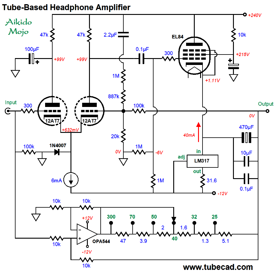
Note the added two 100pF capacitors. Missing from the schematic is a 10pF capacitor across the 30k feedback resistor, which does improve the phase margin substantially. Another possible approach is to forgo the solid-state enhancement and stick to pure-tube circuits. Here is an Aikido-Mojo enhanced headphone amplifier.
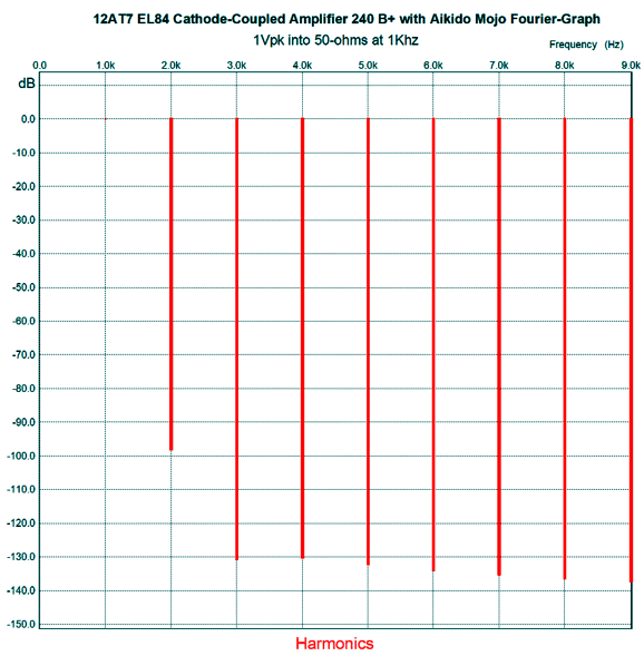
The EL84 is being run in a quasi-pentode mode. Real pentode mode requires that the screen capacitor terminates into the output, not ground. At the same, however, we derive the wonderful pentode-mode feature of enhanced PSRR, as the screen shields the pentode from the power-supply noise. The negative feedback loop extends to the other side of the coupling capacitor. Speaking of coupling capacitors, why have all the previous circuits made use of an output coupling capacitor? Safety. Safety, plain and simple. No one wants to risk damaging their headphones, especially if they cost thousands of dollars. Here is the SPICE-generated Fourier graph for the circuit shown above.
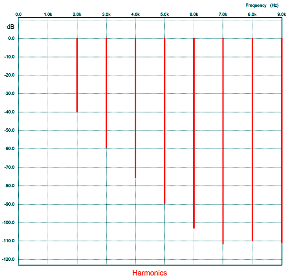
Now, without the Howland current pump's help.
Here is another possible circuit.
The two ECC99 triodes in parallel offer a low output impedance. We also see the same Aikido-Mojo trick of injecting a small portion of the power-supply noise into the negative feedback loop, so the PSRR is greatly enhanced. Needless to say, if I had more time and if my fingers didn't give out, I would show a dozen more possible circuits. The important aspect, however, is the Howland current pump, as it allows these relatively week tube-based headphone amplifiers to roar into 25-ohm headphones.
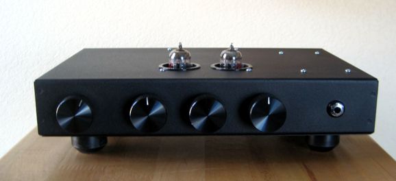
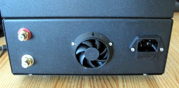
Truly Finished Project
With short feet, this lack of ventilation holes could cause too much heat within the chassis. But with 1-inch tall feet, plenty of air flows around the enclosure, whose black surface works well to dissipate excess heat, as air convection currents circle within the enclosure, moving hot air over cool steel.
Transformer-Coupled MOSFET Output Stages
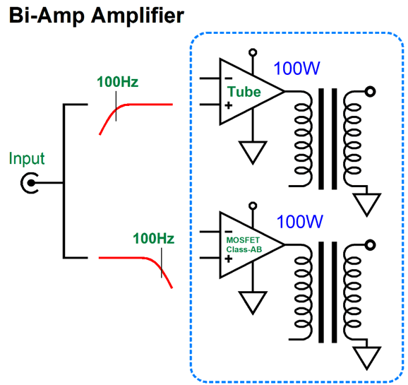
My idea is that we would use a small output transformer for the tubes, say a single ST-70 transformer; but limit its bandwidth to frequencies above 100Hz (or higher), so we can get far more output power from it, say 100W, not 35W. We then would use a power-supply toroidal transformer as the MOSFET amplifier's output transformer, which are readily available and cheap relative to tube output transformers, especially 100W output transformers.
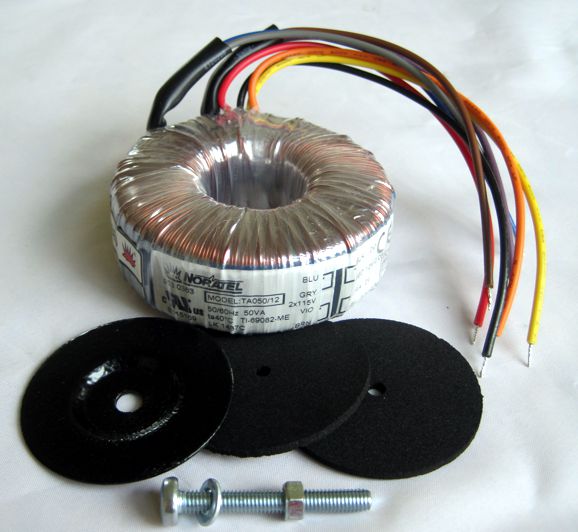
Can power-supply toroid transformers be used as output transformers? They can. In fact, many have done so. The most famous and successful has been UK's Susan parker's original Zeus amplifier, which used power-supply toroids both for the input and output transformers. Her amplifier held only two active devices: the power MOSFETs! This makes the Zen amplifier look complicated in comparison.
I experimented with power-supply toroid transformers a great deal when they became readily available in the early 1980s. What I noted was that they worked surprisingly well as output transformers, especially at low frequencies, and that most were extremely intolerant of sustained unidirectional DC current flow. In contrast, the average output transformer on a tube amplifier could withstand a far greater amount of DC current imbalance. Why? The tube output transformer's I and E laminations intrinsically held enough slop in their construction to create an implicit air-gap, whereas the toroid's tight magnetic circuit, the result of a single long strip of iron wound into a donut, didn't.
Many toroids hold dual primaries and secondaries, as the two primaries allow use in both the USA and Europe, while the two secondary windings allow paralleling or series arrangement, with a center-tap. Since power-supply toroid transformers are specified in input and output voltages, we must perform the math needed to get to impedance ratios. A transformer's impedance ratio is equal to the square of its voltage ratio. For example, a power-supply toroid transformer with a primary voltage of 120Vac and a secondary voltage of 12Vac exhibits a winding and voltage ratio of 10:1, so its impedance ratio is equal 10² or 100:1. If we load the secondary with an 8-ohm loudspeaker, the reflected impedance on the primary will be 800 ohms. By the way, the transformer's current ratio is the inverse of the winding and voltage ratio; thus, a 10:1 voltage ratio implies a 1:10 current ratio. Force 1A of AC current through the primary and the secondary sees a current flow of 10A.
If we follow Ms. Parker's lead and run the two output MOSFETs as source followers, we get low distortion and output impedance. The price we must pay is providing a huge balanced input signal, which is the result of the high-voltage power-supply voltage, say 400Vdc. Let's say that the center-tapped primary saw a peak voltage swing of 700V, which with a winding ratio of 10:1 produces 70V peak voltage swing from the secondary and 306W into an 8-ohm loudspeaker. This assumes class-A amplifier operation, which is unlikely. More likely, the MOSFET output stage will run in class-AB, so at full output, only half of the primary is engaged. The math then becomes 350Vpk² divided by 400 ohms, which yields the same 306W. If only half of the primary is used, the winding ratio is halved (5:1), so the impedance ratio is reduced to a fourth (250:1), as impedance ratio equals winding ratio squared, leaving us with a 200-ohm load. The formula for AC wattage is Power = V²/2∙Rload. We find the peak current flow by dividing the peak voltage swing (350V) by the half-primary impedance of 200 ohms; we get 1.75Apk as the answer. If we assume a more modest amount of power, say only 100W, we must work backwards. Assuming the same 350V of peak voltage swing, we divide twice the watts by 350V, which gives the peak current swing at 100W on the primary (572mA). Next, we divide 350V by the peak current of 572mA and get the load impedance of 612.5 ohms. I like to check my math along the way, so I square 350V and divide by twice the load impedance of 612.5 (1225 ohms) and the result is 100W. Our next step is to find the winding ratio between half the primary and the secondary. Assuming an 8-ohm load, we divide the primary impedance of 612.5 ohms by 8 ohms and get the needed impedance ratio, 76.5625:1. The winding and voltage ratio is equal to the square root of the winding and voltage ratio; thus, 8.75:1. Now, we must find an existing power-supply toroid transformer that offers the right voltage ratio. Many, if not most, toroid transformers hold two 115Vac primary windings, so we divide 115 by 8.75 and we get 13.14Vac. Not good, as no one makes a 13Vac toroid transformers—well, at least not one with a VA rating of 500. We can, however, buy huge 12Vac and 15Vac transformers. If we used the 12Vac transformer, the MOSFET would have to swing more than 350V to get 100W into an 8-ohm load. How much more? The answer is 33V more, bringing the total to 383Vpk, which puts us much closer to the 400Vdc B+ voltage. Is that a problem? Yes, as we can expect power-supply rail voltage droop at full output, the exact amount depending on the power-supply transformer. If we opt for the 15Vac transformer, the MOSFETs need only swing 306Vpk to deliver 40Vpk to the loudspeaker. The problem now is that if the power-supply rail voltage doesn't droop, the MOSFETs will become hotter due to the large drop across them and the high peak current flow. Of course, if the power supply can support continuous 350Vpk voltage swings, then we would get more than 100W. How much more? One way to find out is to divide 350Vpk by voltage ratio, which equals 115V/15V or 7.66:1; and 350V/7.66 equals 45.65Vpk, which across an 8-ohm load equals 45.65V²/(2 ∙ 8) or 130W. If we realize 130W of output power, what VA rating should the transformer be rated? Remember we expect it to pass frequencies far below 50Hz or 60Hz, as in 20Hz. I would seek a monster of a transformer with a VA rating of 500VA, such as the Antek AN5412 and AN5415. Both transformers hold four secondaries.
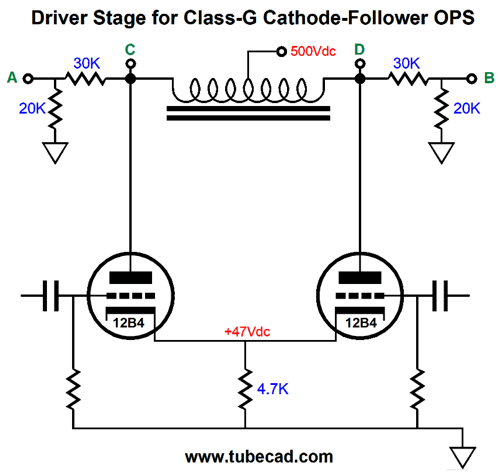
What remains is the problem of driving the source follower output stage. I have covered cathode follower output stages many times before, so I won't extensively repeat myself again. In order to use the 400V B+ voltage, a center-tapped inductor loading a tube-based differential amplifier stage would probably prove the best path to follow. Here is one possible driver stage from post 522, with the exception of the 30k and 20k resistors.
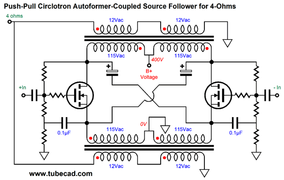
With the lower B+ voltage of 400Vdc, the 15Vac transformer is the better choice than the 12Vac transformer, due to the limited output swing from this driver stage. (The triodes must drop some voltage to operate; and this voltage drop robs us of potential voltage swing.) Another possibility is to go the circlotron route, which effectively halves the needed input signal, as the circlotron effectively realizes a gain of 1:2 (6dB). In addition, the output transformer's primary only sees half the peak voltage swing than it would in the cathode-follower configuration; this allows us to use a lower winding ratio—and to get sneaky.
Two transformers are needed—but they can be half the VA rating of one big output transformer. Well, that is true if we are driving either 8-ohm or 16-ohm speakers with the circuit shown above. If the speakers are 4-ohm types, then the following arrangement is the way to go.
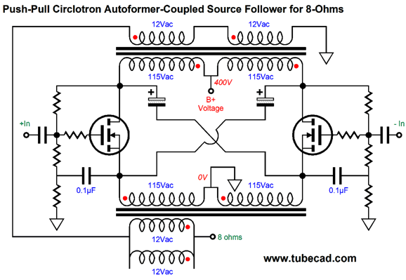
Note how the secondaries are in parallel, so each transformer shares half the work of powering the speaker. In fact, with 8-ohm loads, the following would be a better way to proceed.
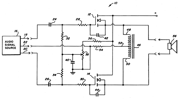
Another possibility is to take inspiration from Warren E. Gilson's 1978 US patent 4,096,443, BALANCED SOURCE FOLLOWER AMPLIFIER.
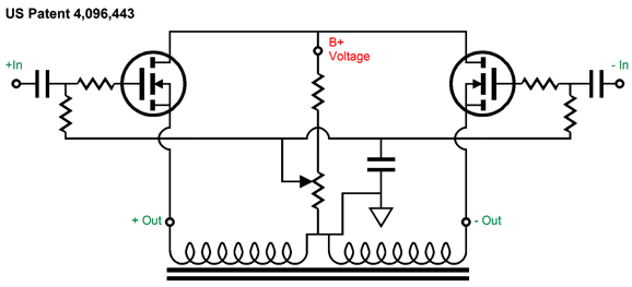
Patent schematics make our eyes hurt. Here it is redrawn.
Now, the patent's Abstract statement:
Next, the patent's summery of the invention:
Deep within the patent, we find this pearl:
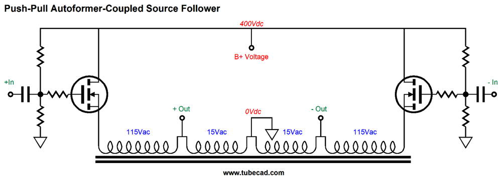
Okay, how do we make an inductor-loaded source follower that runs off of a B+ voltage of 400Vdc? This is how.
What we have here is an autoformer, not at transformer. The huge voltage swings across the single winding are reduced in voltage but increased in current at the two output taps. In other words, we have taken a power transformer and wired it up as a multi-tapped autoformer. An added feature is that autoformers offer twice the VA rating of the same-sized transformer. Okay, what about a hybrid approach, which mixes a center-tapped inductor with a transformer.
This power buffer runs off of only 24Vdc, yet could deliver 100W into either an 8-ohm or 4-ohm load. Yes, we have abandoned the 400Vdc B+ voltage. We could also wire it up as an autoformer.
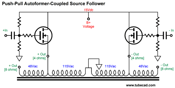
One last variation on this theme.
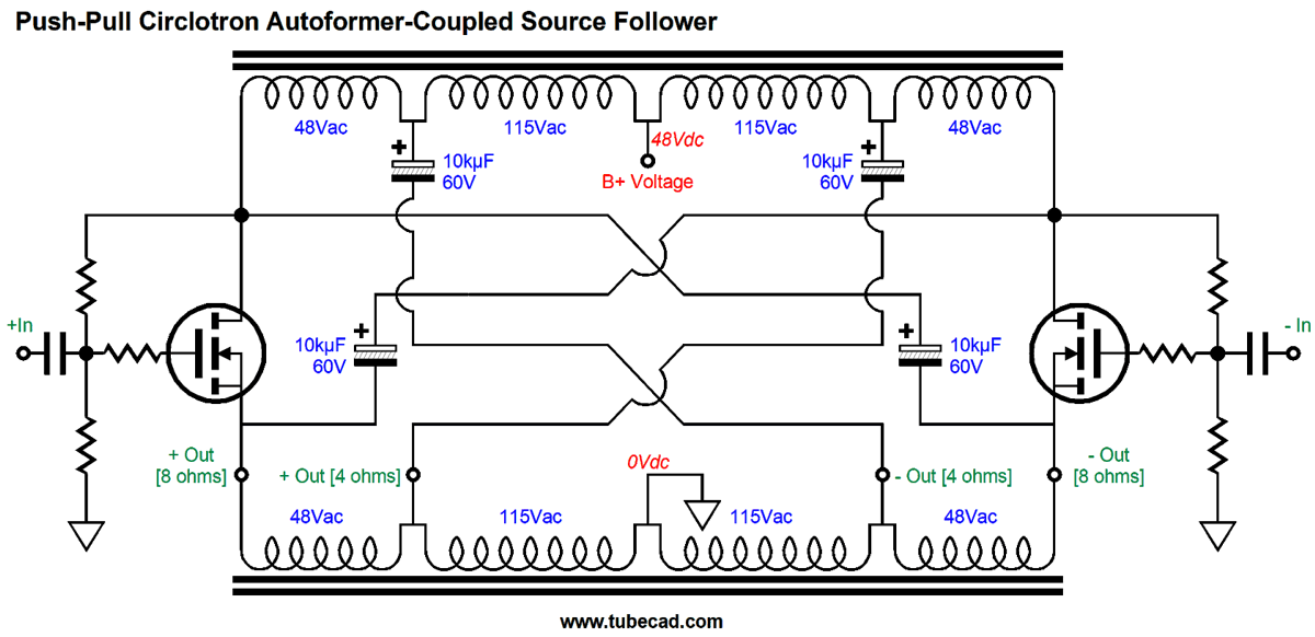
Note the reduction in B+ voltage. With this setup, the autoformer provides gain into 8-ohm loads. Now we return to the circlotron. The following design must use the 48Vdc B+ voltage to deliver 100W.
I would love to send this schematic back in time to Mr. Gilson in 1978. One huge advantage to the circlotron topology is that none of the windings are ever left flapping in the air, as the crisscrossing capacitors hold all in a tight embrace. This is the power buffer I would love to hear.
Music Recommendation: Quietly There
//JRB
Very few can imagine just how much hard work is required to make one of my posts. If you have any sort of inkling or intuition of what is envolved, please think about supporting me at Patreon.
User Guides for GlassWare Software
For those of you who still have old computers running Windows XP (32-bit) or any other Windows 32-bit OS, I have setup the download availability of my old old standards: Tube CAD, SE Amp CAD, and Audio Gadgets. The downloads are at the GlassWare-Yahoo store and the price is only $9.95 for each program. http://glass-ware.stores.yahoo.net/adsoffromgla.html So many have asked that I had to do it. WARNING: THESE THREE PROGRAMS WILL NOT RUN UNDER VISTA 64-Bit or WINDOWS 7 & 8 & 10 or any other 64-bit OS. I do plan on remaking all of these programs into 64-bit versions, but it will be a huge ordeal, as programming requires vast chunks of noise-free time, something very rare with children running about. Ideally, I would love to come out with versions that run on iPads and Android-OS tablets.
//JRB
|
|
I know that some readers wish to avoid Patreon, so here is a PayPal button instead. Thanks. John Broskie
John Gives
Special Thanks to the Special 86
I am truly stunned and appreciative of their support. In addition I want to thank the following patrons:
All of your support makes a big difference. I would love to arrive at the point where creating my posts was my top priority of the day, not something that I have to steal time from other obligations to do. The more support I get, the higher up these posts move up in deserving attention. If you have been reading my posts, you know that my lifetime goal is reaching post number one thousand. I have 475 more to go. My second goal was to gather 1,000 patrons. Well, that no longer seems possible to me, so I will shoot for a mighty 100 instead. Thus, I have 14 patrons to go. Help me get there.
Only $12.95 TCJ My-Stock DB
Version 2 Improvements *User definable Download for www.glass-ware.com |
||


| www.tubecad.com Copyright © 1999-2020 GlassWare All Rights Reserved |